
ECSB 4WD 4l60E to 4l80E
 Nov 27, 2008 | 11:38 PM
#121
 Nov 28, 2008 | 11:25 AM
#123
Thread Starter
TECH Senior Member
iTrader: (7)
Joined: Jun 2004
Posts: 5,446
Likes: 7
From: Central Kentucky
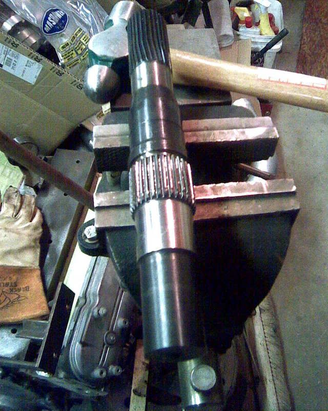
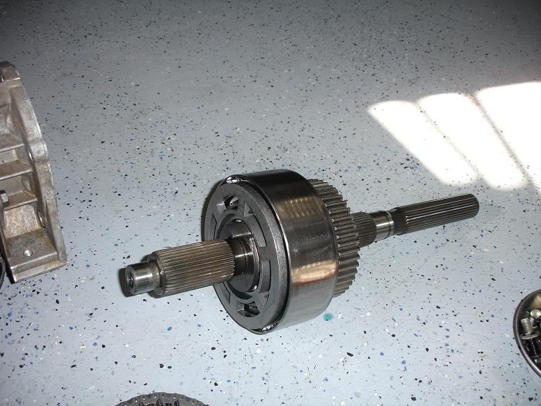
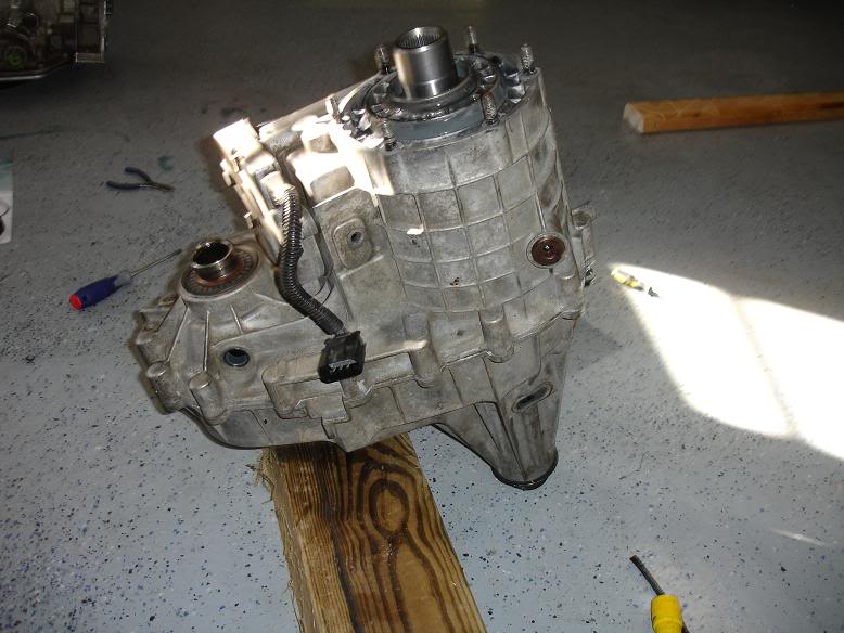
Tearing into the transfer case to swap out the input shaft so it will fit an 80e. Already a good write-up on the board that I referenced for this. Thanks Wilde... Still gonna add my 2 cents.

Found this clip piece laying under the pump pickup. Had to pack up and head to the dealer. Luckily he had the new design clip in stock. Also had to pickup up some more tools.... 12mm allen for the next steps. I'll show the new clip later.
Found this clip piece laying under the pump pickup. Had to pack up and head to the dealer. Luckily he had the new design clip in stock. Also had to pickup up some more tools.... 12mm allen for the next steps. I'll show the new clip later.
Last edited by KySilverado; Nov 29, 2008 at 08:27 AM.
Nov 28, 2008 | 04:05 PM
#124
Thread Starter
TECH Senior Member
iTrader: (7)
Joined: Jun 2004
Posts: 5,446
Likes: 7
From: Central Kentucky
Transfer case is all buttoned back up, mostly. I tore up the front seal getting it out and can't get another till next week.
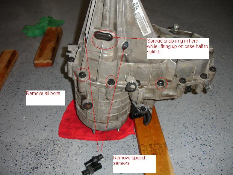
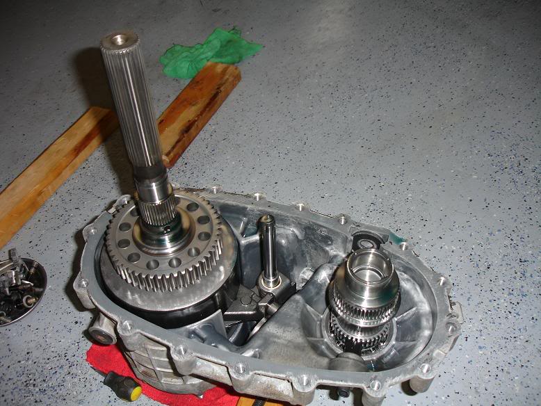
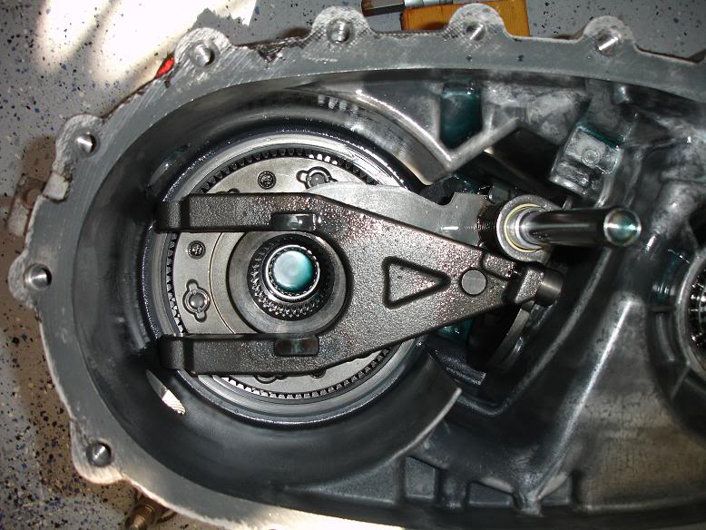
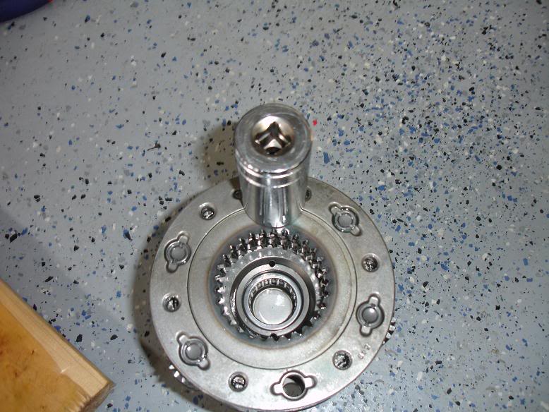
This assembly will just lift out with a little finessing.
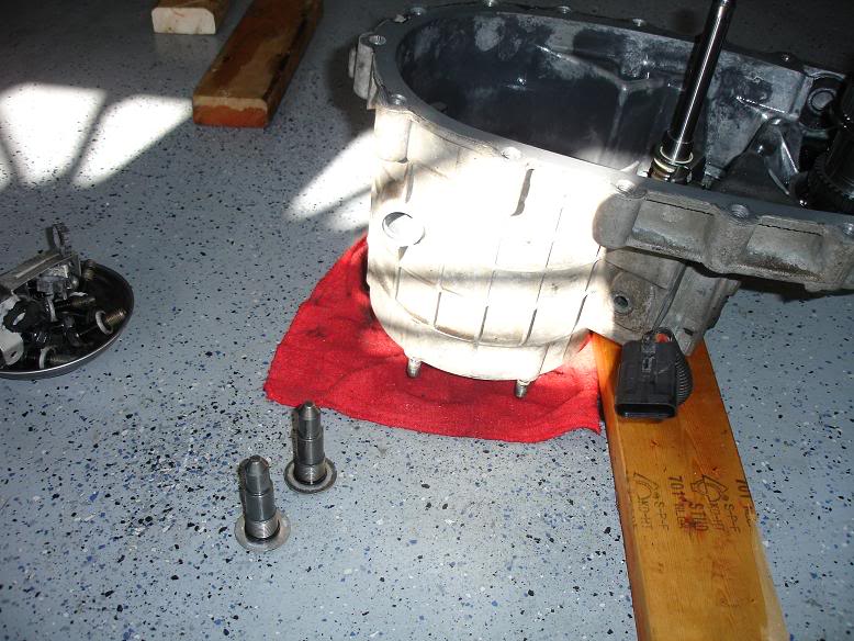
Need to remove these 2 bolts. 12mm allens required.
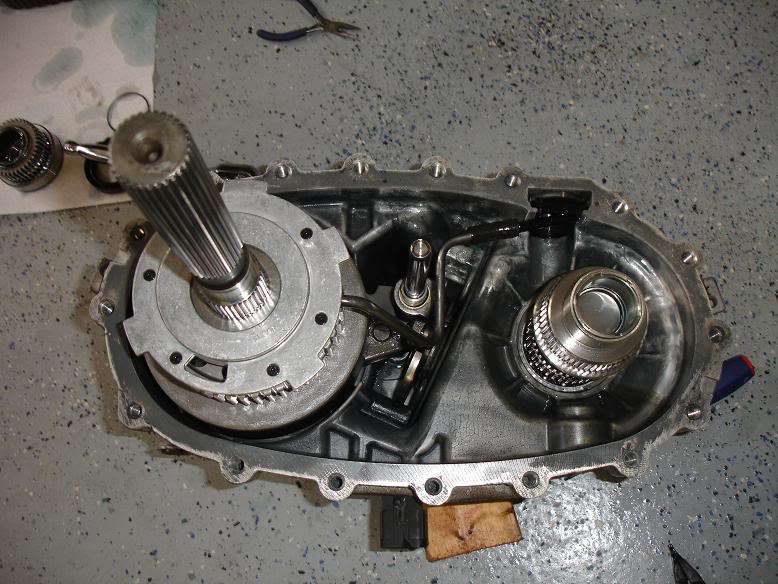
Lift this fork out, and pull the rod to the right. Some fancy manuvering will then pull a gear out of the spiders and the shifting mechanism. Take your time here.
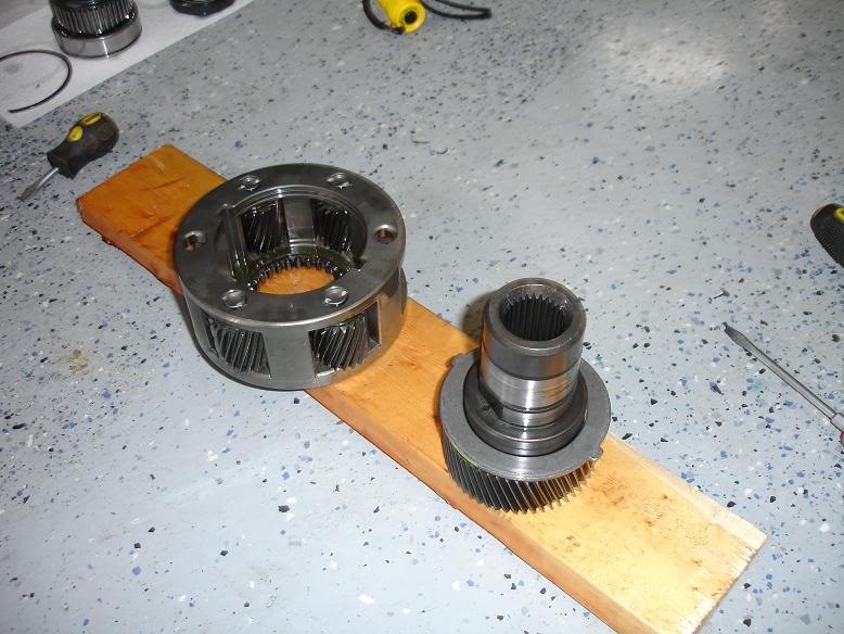
Remove front seal and a couple c-clips to get to this.
Had to drive in the needle bearings that cam with the new input shft.
Going back together.
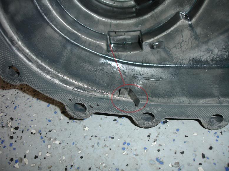
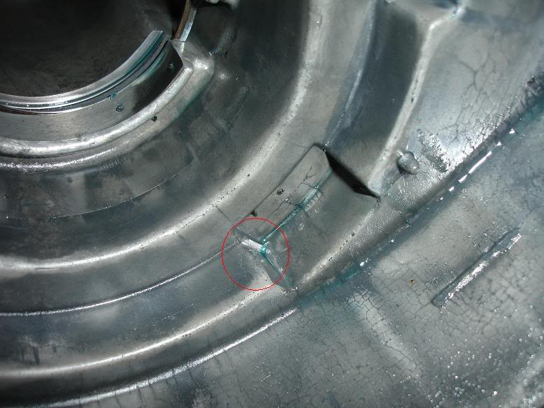
Some case damage form the clip breaking. I'd had a leak here eventually about half the case wall gone.
The new design clip on.
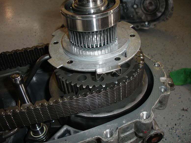
Had to flip the case over like this to allow everything to settle downward to get the final c-clip to snap back in. This was a PITA.
This assembly will just lift out with a little finessing.
Need to remove these 2 bolts. 12mm allens required.
Lift this fork out, and pull the rod to the right. Some fancy manuvering will then pull a gear out of the spiders and the shifting mechanism. Take your time here.
Remove front seal and a couple c-clips to get to this.
Had to drive in the needle bearings that cam with the new input shft.
Going back together.
Some case damage form the clip breaking. I'd had a leak here eventually about half the case wall gone.
The new design clip on.
Had to flip the case over like this to allow everything to settle downward to get the final c-clip to snap back in. This was a PITA.
Last edited by KySilverado; Nov 29, 2008 at 06:14 PM.
Nov 29, 2008 | 11:00 AM
#125
Thread Starter
TECH Senior Member
iTrader: (7)
Joined: Jun 2004
Posts: 5,446
Likes: 7
From: Central Kentucky
Hmmm... no comments the last couple days. I must really be boring everyone 
Some of the wiring this morning.
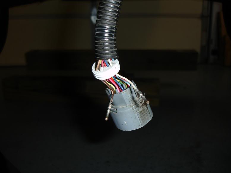
The main connector with the cover removed. Pull the rubber plug back to give some room to pull the 2 wires necessary.

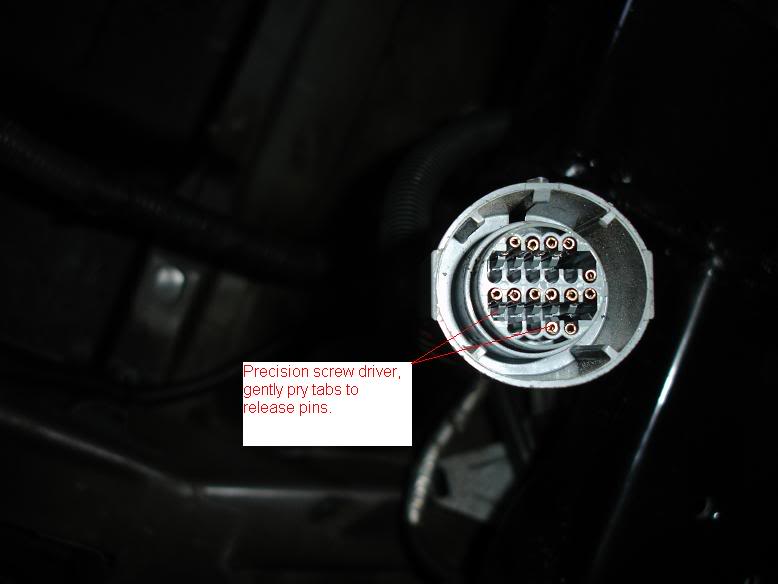
View from the business end.
The 2 wires removed. Place them back into the locations detailed earlier and snap everything back together.
Some of the wiring this morning.
The main connector with the cover removed. Pull the rubber plug back to give some room to pull the 2 wires necessary.
View from the business end.
The 2 wires removed. Place them back into the locations detailed earlier and snap everything back together.
Nov 29, 2008 | 11:57 AM
#126
Oh, believe me, I'm reading EVERYTHING you post on this,  . I'm ordering the rebuild kit, TranGo and a Edge converter for mine on Monday,
  I'm not too far behing you and glad your doing such a detailed write up.
I'm not too far behing you and glad your doing such a detailed write up.
 Nov 29, 2008 | 12:44 PM
#128
Thread Starter
TECH Senior Member
iTrader: (7)
Joined: Jun 2004
Posts: 5,446
Likes: 7
From: Central Kentucky
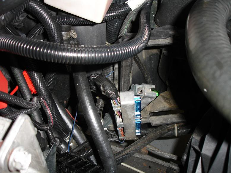
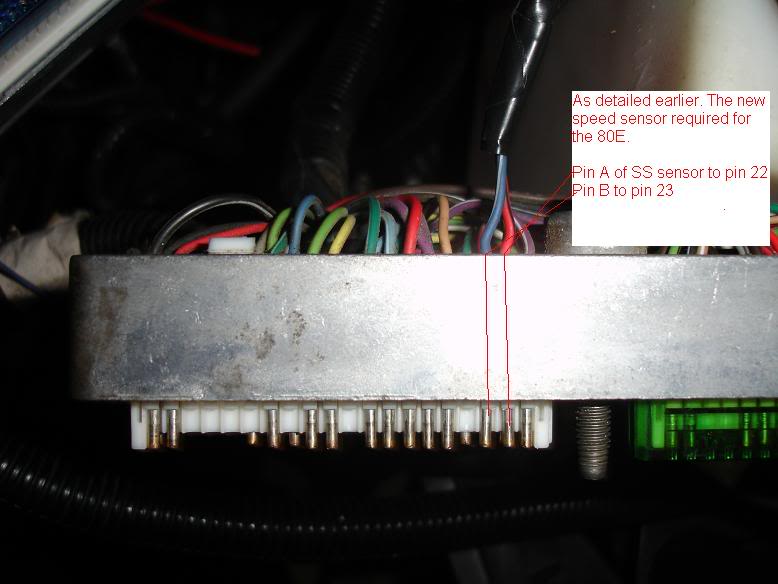
Well on to getting the speed sensor wired. I actually gave up on this earlier. The key was getting the damn PCM connectors up to where I could work on them. I actually pulled the PCM out to get it out of the way. Probably not necessary.
Once I got the connectors up to where I could work on them after getting the back covers off, I took a small drill bit and ran it through the pin locations to open up the water seals. I've seen a paper clip used but couldn't find one.
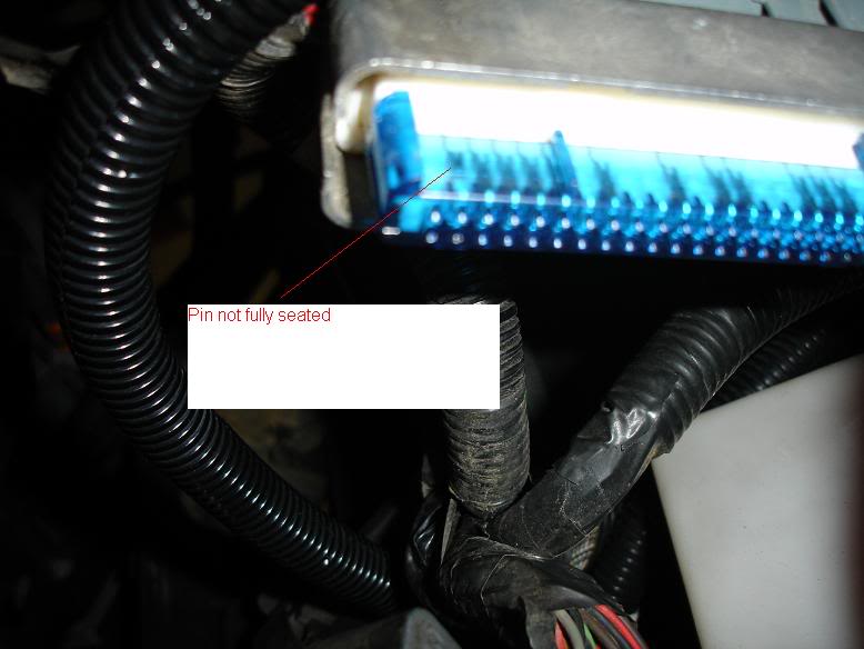
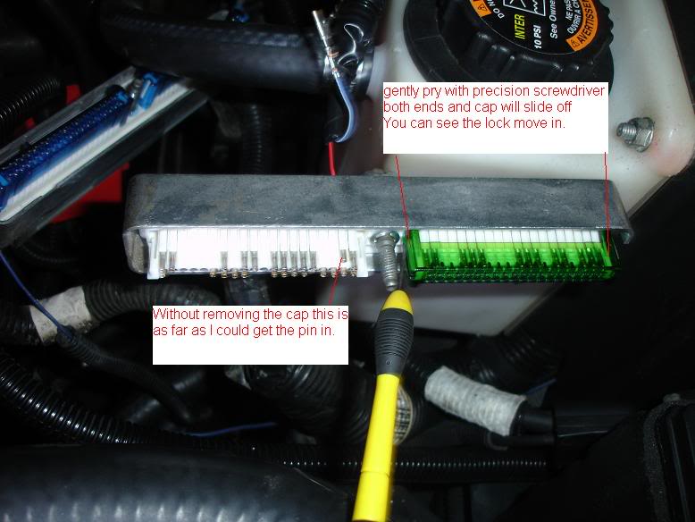
I also could not get the pin to fully seat into the connector. I even looked at a previous pin I'd put in for the electric fans it was the same way. May be common knowledge but I've not seen it mentioned but after fooling with this I'm gonna say that you cannot get PCM pins all the way in without removing these covers I've pictured. The caps lock the pin locking tabs down and don't allow them to flex out of the way as you slide the pin in.
The pin for fan done couple years ago. I also took it apart and fixed it.
A shot to show how I managed to get the connectors up where I could work on them.

Once I got the connectors up to where I could work on them after getting the back covers off, I took a small drill bit and ran it through the pin locations to open up the water seals. I've seen a paper clip used but couldn't find one.
I also could not get the pin to fully seat into the connector. I even looked at a previous pin I'd put in for the electric fans it was the same way. May be common knowledge but I've not seen it mentioned but after fooling with this I'm gonna say that you cannot get PCM pins all the way in without removing these covers I've pictured. The caps lock the pin locking tabs down and don't allow them to flex out of the way as you slide the pin in.
The pin for fan done couple years ago. I also took it apart and fixed it.
A shot to show how I managed to get the connectors up where I could work on them.
