
Custom machined catch can! (pics inside)
 Apr 9, 2014 | 09:44 PM
#1

Hey guys my catch can is done now thought I would share some pics, would like to here your thoughts before I install it.
Here are all the parts together.
[IMG] [/IMG]
Top chamber (dirty side).
[IMG] [/IMG]
Inside of chamber what material should I pack this with?????
[IMG] [/IMG]
Plug for chamber once I pack it.
[IMG] [/IMG]
bottom of can with drain plug.
[IMG] [/IMG]
Pressing on bottom of can.
[IMG] [/IMG]
Top of can assembled and ready to be pressed on.
[IMG]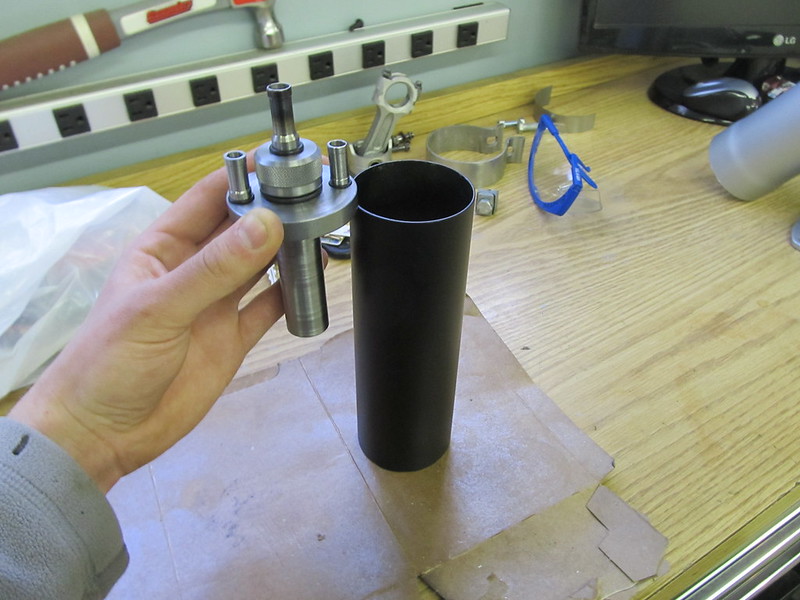 [/IMG]
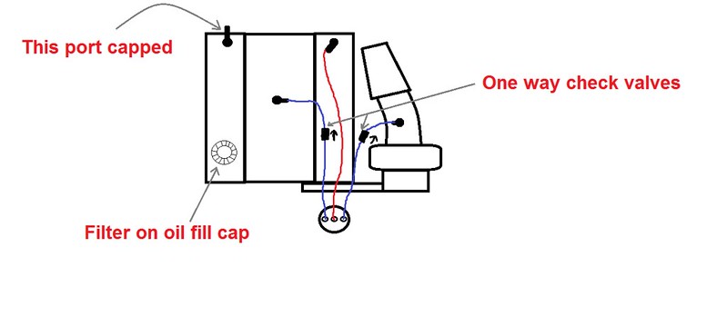
I was going to throw a breather on the oil fill cap then plumb the can like this.
[IMG] [/IMG]
Can fully assembled.
[IMG]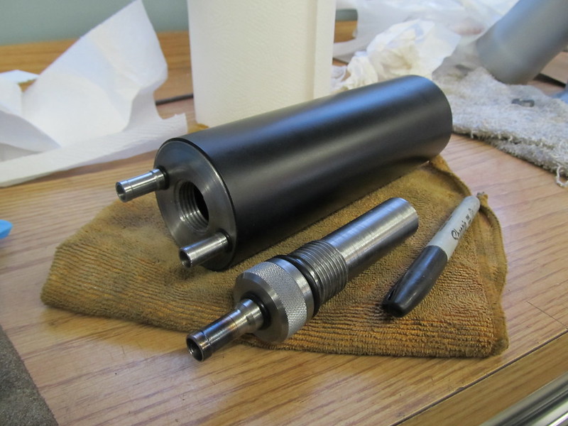 [/IMG]
[IMG] [/IMG]
Ready to install!!
[IMG]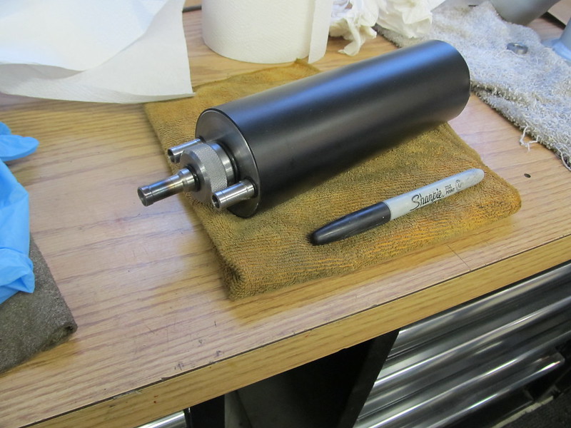 [/IMG]
What do you guys think? Will it work? If so what should I pack the chamber with?
Here are all the parts together.
[IMG]
[/IMG]Top chamber (dirty side).
[IMG]
[/IMG]Inside of chamber what material should I pack this with?????
[IMG]
[/IMG]Plug for chamber once I pack it.
[IMG]
[/IMG]bottom of can with drain plug.
[IMG]
[/IMG]Pressing on bottom of can.
[IMG]
[/IMG]Top of can assembled and ready to be pressed on.
[IMG]
[/IMG] I was going to throw a breather on the oil fill cap then plumb the can like this.
[IMG]
[/IMG]Can fully assembled.
[IMG]
[/IMG] [IMG]
[/IMG]Ready to install!!
[IMG]
[/IMG]What do you guys think? Will it work? If so what should I pack the chamber with?
Last edited by jroctpb; Apr 9, 2014 at 11:03 PM.
Apr 9, 2014 | 10:18 PM
#2

the inside of my Mike Norris catch can was a tight knit cotton like material in a screen. I'd think you'd want a way of keeping it together so you don't run the potential of sucking some threw.
I think you'll need a check valve or something wont you for boost conditions? aren't most guys adding a T-Bird PCV valve in the line somewhere?
I think you'll need a check valve or something wont you for boost conditions? aren't most guys adding a T-Bird PCV valve in the line somewhere?
Apr 9, 2014 | 10:28 PM
#3
Yeah I may have to change up the bottom plug a little depending on what type of material ends up in the chamber. and yeah I am going to put in line check valves on both the (clean side) lines.


 Apr 10, 2014 | 07:52 AM
#6


Joined: Jan 2006
Posts: 16,282
Likes: 438
From: Huntsville, AL
Steel wool is not a good choice. Once its saturated it will not help condense the oil vapors any.
I would not do the line to the top of the intake manifold. It will be closed off under boost from a check valve (as it should), so not doing anything anyway.
Or you could put the one to the intake manifold with a check valve to close under boost, and put the other side on a breather with a check valve set to open under boost. So you get vacuum under normal driving, and venting under boost so you dont boost the crankcase. Should also avoid oil injestion by the procharger under boost.
Apr 10, 2014 | 11:08 AM
#7
I may switch to 90s depending on where I end up mounting it, I started with straight ones because I was told to mount it as low as possible. There's very little room on the drivers side of the engine bay so I will have to get creative.
Trending Topics
Apr 10, 2014 | 11:16 AM
#8
Steel wool is not a good choice. Once its saturated it will not help condense the oil vapors any.
I would not do the line to the top of the intake manifold. It will be closed off under boost from a check valve (as it should), so not doing anything anyway.
Or you could put the one to the intake manifold with a check valve to close under boost, and put the other side on a breather with a check valve set to open under boost. So you get vacuum under normal driving, and venting under boost so you dont boost the crankcase. Should also avoid oil injestion by the procharger under boost.
I would not do the line to the top of the intake manifold. It will be closed off under boost from a check valve (as it should), so not doing anything anyway.
Or you could put the one to the intake manifold with a check valve to close under boost, and put the other side on a breather with a check valve set to open under boost. So you get vacuum under normal driving, and venting under boost so you dont boost the crankcase. Should also avoid oil injestion by the procharger under boost.
Apr 10, 2014 | 11:25 AM
#9
Joined: Jan 2006
Posts: 16,282
Likes: 438
From: Huntsville, AL
Yes exactly....you want to A.) avoid boosting the crankcase, and B.) give the air somewhere to go under boost because no matter how well your cylinders seal you will get some blowby and if you dont vent that air the pressure will start pushing seals.
Apr 10, 2014 | 11:28 AM
#10
You want the Procharger valve flowing toward the blower . Away from the catch can.
The only prob w that is when you are normal driving and idle the can will not use the ~18 inches of vac from the intake. It will share the blower and intake manifold vac which is better than nothing but not as good as using manifold vac for anything out of boost.
So Make a second can. 1 can to the intake and valve cover w a check valve. 2 can for the other valve cover and blower inlet.