Preston129/BlkSlvrdo129 Build thread - TVS1900, EPS cam and more
 Jun 29, 2011 | 09:22 PM
#171

I'm behind on some of my status updates from last weekend, so here are the lost pics of Day 9 and 10:
Day 9: Ran the water lines for the intercooler and reinstalled the rad and fans.
Earl's Pro-Lite Ultra hose in -12:

I didn't like the bend in the inlet hose to the heat exchanger, was starting to kink a little, so I used one of the two molded 90� bends I wasn't using for the intercooler barbs:


I used these 45� -12 fittings from Earl's to connect the hoses to the larger water tank:

These fittings are REALLY light:

This is the finished line for the outlet of the water tank to the inlet of the aux water pump. Had to redo this one as the spot where I had it wouldn't work once the radiator was reinstalled:

Had to make it longer to loop over the inlet line on the water tank. Not the cleanest looking way to run it, but braided line is a lot more rigid than rubber hose, so your options of bending it how you like are very limited:

Here I've got most of the lines run where I want them and starting to tie-wrap everything together:

This was the first way I ran the outlet line:

Pic of the water pump and how the lines are run:

I like the look of the braided line compared to the rubber one:

Rad and fans back in and rad hoses all connected:


Last pic before the intake tube goes on:

Day 9: Ran the water lines for the intercooler and reinstalled the rad and fans.
Earl's Pro-Lite Ultra hose in -12:
I didn't like the bend in the inlet hose to the heat exchanger, was starting to kink a little, so I used one of the two molded 90� bends I wasn't using for the intercooler barbs:
I used these 45� -12 fittings from Earl's to connect the hoses to the larger water tank:
These fittings are REALLY light:
This is the finished line for the outlet of the water tank to the inlet of the aux water pump. Had to redo this one as the spot where I had it wouldn't work once the radiator was reinstalled:
Had to make it longer to loop over the inlet line on the water tank. Not the cleanest looking way to run it, but braided line is a lot more rigid than rubber hose, so your options of bending it how you like are very limited:
Here I've got most of the lines run where I want them and starting to tie-wrap everything together:
This was the first way I ran the outlet line:
Pic of the water pump and how the lines are run:
I like the look of the braided line compared to the rubber one:
Rad and fans back in and rad hoses all connected:
Last pic before the intake tube goes on:
Jun 29, 2011 | 09:24 PM
#172
Almost caught up, here's pics from Day 10:
Got a couple 4" black silicone hose couplers (one hump, one straight) thinking I could get away with the straight coupler instead of the corrugated flexible one that comes in the kit from magnacharger:

Lingenfelter 100mm MAF housing and cartridge style sensor compared to stock 85mm:


Stock 85mm. I upgraded to the 100mm both for increased cross sectional area and because the cartridge style MAF doesn't have the separating bar. I also want to fab up a 4" intake tube out of aluminum one day so this will fit nicely with the look I'm going for:

Big Lingenfelter:

Mocked up with the two couplings I bought. My intent was to not use the corrugated flex coupler just on the basis that a lot of ridges would disrupt airflow more than a straight path, but after standing back I really didn't think the straight coupler looked that good on there:

And obviously wouldn't work because the straight coupler leaves too much room between the airtube and inlet on the supercharger:

Just a pic of it on it's own:

Put the old intake manifold on the tailgate to remove the throttle body:

As hard as I tried to get a good pic of the plenum area behind the throttle body, I just couldn't get enough light inside it, so these pics aren't the greatest but here's what's inside our manifolds:

Gotta take the top two studs out, and if anyone ever needs to do the same, you need an inverted #5 Torx bit:

Going back to what I've said earlier about the importance of a catch can, I wiped the inside of the plenum a bit and this is what I came away with:

And because it's come up before, and people ask why I switched to a 90mm throttle body; the plenum opening on the NNBS intake manifold really is 90mm in diameter:

But to be fair, the inside of the manifold right after the opening has a reduction on it, so you're not getting a "true" 90mm directly into the plenum:

No such reductions on the maggie's inlet, this thing's made to inhale tons of airflow:


So after all my planning, I did end up using the flexible coupler:


Got a couple 4" black silicone hose couplers (one hump, one straight) thinking I could get away with the straight coupler instead of the corrugated flexible one that comes in the kit from magnacharger:
Lingenfelter 100mm MAF housing and cartridge style sensor compared to stock 85mm:
Stock 85mm. I upgraded to the 100mm both for increased cross sectional area and because the cartridge style MAF doesn't have the separating bar. I also want to fab up a 4" intake tube out of aluminum one day so this will fit nicely with the look I'm going for:
Big Lingenfelter:
Mocked up with the two couplings I bought. My intent was to not use the corrugated flex coupler just on the basis that a lot of ridges would disrupt airflow more than a straight path, but after standing back I really didn't think the straight coupler looked that good on there:
And obviously wouldn't work because the straight coupler leaves too much room between the airtube and inlet on the supercharger:
Just a pic of it on it's own:
Put the old intake manifold on the tailgate to remove the throttle body:
As hard as I tried to get a good pic of the plenum area behind the throttle body, I just couldn't get enough light inside it, so these pics aren't the greatest but here's what's inside our manifolds:
Gotta take the top two studs out, and if anyone ever needs to do the same, you need an inverted #5 Torx bit:
Going back to what I've said earlier about the importance of a catch can, I wiped the inside of the plenum a bit and this is what I came away with:
And because it's come up before, and people ask why I switched to a 90mm throttle body; the plenum opening on the NNBS intake manifold really is 90mm in diameter:
But to be fair, the inside of the manifold right after the opening has a reduction on it, so you're not getting a "true" 90mm directly into the plenum:
No such reductions on the maggie's inlet, this thing's made to inhale tons of airflow:
So after all my planning, I did end up using the flexible coupler:
Jun 29, 2011 | 09:25 PM
#173
Day 10 cont'd:
Next job was to modify the factory pigtail connector for the MAF so that I could use the new cartridge style MAF. MAF swaps are NOT plug and play, you really need to pay attention to the wiring pinouts because you could be setting yourself up for a hell of a hard time trying to troubleshoot MAF table errors.
On the left is the stock unmodified connector and on the right is an adapter pigtail I got with the Lingenfelter MAF. The other end of it was designed to work on a Gen III engine, so I couldn't use it, but it was helpful to get the proper order of the wires. To go from the stock 85mm MAF to a newer style cartridge MAF, the pink and black wires need to swap positions:

To get at the wires, unwrap some of the electrical tape and pop out the purple retainer clip:

Then just pull the wire straight out of the connector. I found doing this by hand felt safer than trying to use a pair of pliers, you just need to get enough of the wire in your hand:

Reinstalled in the proper order for the new MAF:

Final couple pics, basically all done at this point except for adding fluid:


This part of the truck gave me a little hesitation because I'm not sure if the hoses will have any clearance problems with the grille, but I don't think I'll have any problems. I also had to remove the plastic sheet that covers the space between the rad and headlight in order to get the water lines through. I don't know if this piece is worth modifying to reinstall, it'd be nice to have something keeping dirt and **** away from the aux water pump and rest of the engine bay, but maybe the added aiflow will help keep the aux pump cooler...something I'll keep an eye on.

Next job was to modify the factory pigtail connector for the MAF so that I could use the new cartridge style MAF. MAF swaps are NOT plug and play, you really need to pay attention to the wiring pinouts because you could be setting yourself up for a hell of a hard time trying to troubleshoot MAF table errors.
On the left is the stock unmodified connector and on the right is an adapter pigtail I got with the Lingenfelter MAF. The other end of it was designed to work on a Gen III engine, so I couldn't use it, but it was helpful to get the proper order of the wires. To go from the stock 85mm MAF to a newer style cartridge MAF, the pink and black wires need to swap positions:
To get at the wires, unwrap some of the electrical tape and pop out the purple retainer clip:
Then just pull the wire straight out of the connector. I found doing this by hand felt safer than trying to use a pair of pliers, you just need to get enough of the wire in your hand:
Reinstalled in the proper order for the new MAF:
Final couple pics, basically all done at this point except for adding fluid:
This part of the truck gave me a little hesitation because I'm not sure if the hoses will have any clearance problems with the grille, but I don't think I'll have any problems. I also had to remove the plastic sheet that covers the space between the rad and headlight in order to get the water lines through. I don't know if this piece is worth modifying to reinstall, it'd be nice to have something keeping dirt and **** away from the aux water pump and rest of the engine bay, but maybe the added aiflow will help keep the aux pump cooler...something I'll keep an eye on.
Jun 29, 2011 | 09:26 PM
#174
I should also outline the priming procedure I used before I tried starting the truck for the first time:
This is more important on a freshly built engine, but is still a good idea to get oil flowing up to the top of the engine a little faster when you finally do start the engine.
- I then pulled the fuse for the fuel pump. In my fuse box this was fuse #21 (a 20A fuse).
- After ensuring both spark and fuel systems were disabled, I cranked the engine over with the ignition twice, for about 5 seconds each time.
This is more important on a freshly built engine, but is still a good idea to get oil flowing up to the top of the engine a little faster when you finally do start the engine.
Jun 29, 2011 | 09:30 PM
#175
And now here are some pics from today:
So I'm pretty sure that arrow is pointing to the hose clamp, so I don't forget to tighten the screw, right guys? What else could it be for?

Here's the MAF sensor in the housing the way I had it before (the wrong way):

And now flipped around showing the proper way and reason for why I couldn't get the truck to idle, you can see one of the sensor wires is now able to get airflow across it:

Another pic of the same thing, this time put back inline withe the rest of the intake (the right way):

"Follow the arrow":

Back together. I thought it was going to look stupid having the connector and wiring harness coming in from the front, but I angled it down enough that it's really not too noticeable, plus I like the look of the LPE script this way now too:


And this little fuckup made me feel jesty, so here you go:

When in doubt, blame the tune!!!
Only kidding, Justin's done a great job and is very patient to put up with my (and I'm sure hundreds of other guys') questions at all hours of the day. Can't say enough good things about him and the help he's provided, even before I was a paying customer.
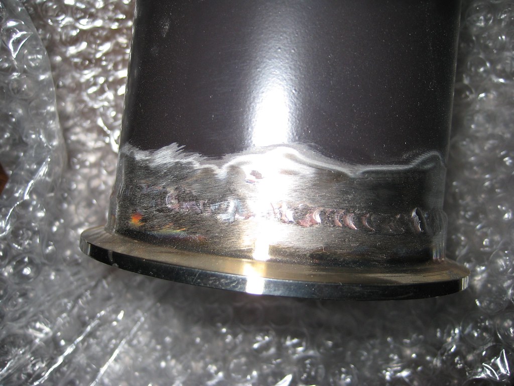
So you guys probably recall I had my exhaust pipes ceramic coated, then after I couldn't get the patch piece [I needed to run a shorter muffler] bent the way I wanted, I finally settled on welding on a V-band clamp, so this is what the exhaust pipe looked like after welding:
So I picked up a can of this high temp BBQ grill paint (good for 1200�F) in flat black to cover up the parts that were ground away:

After 4 coats, here's how it's looking:

Pretty good match actually. Just hope it doesn't flake off. Not that I'm worried about heat, just being a spray can I'm apprehensive of it's durability. I washed everything down with degreaser beforehand, so it should adhere to the metal well enough:

So I'm pretty sure that arrow is pointing to the hose clamp, so I don't forget to tighten the screw, right guys? What else could it be for?
Here's the MAF sensor in the housing the way I had it before (the wrong way):
And now flipped around showing the proper way and reason for why I couldn't get the truck to idle, you can see one of the sensor wires is now able to get airflow across it:
Another pic of the same thing, this time put back inline withe the rest of the intake (the right way):
"Follow the arrow":
Back together. I thought it was going to look stupid having the connector and wiring harness coming in from the front, but I angled it down enough that it's really not too noticeable, plus I like the look of the LPE script this way now too:
And this little fuckup made me feel jesty, so here you go:
When in doubt, blame the tune!!!
Only kidding, Justin's done a great job and is very patient to put up with my (and I'm sure hundreds of other guys') questions at all hours of the day. Can't say enough good things about him and the help he's provided, even before I was a paying customer.
So you guys probably recall I had my exhaust pipes ceramic coated, then after I couldn't get the patch piece [I needed to run a shorter muffler] bent the way I wanted, I finally settled on welding on a V-band clamp, so this is what the exhaust pipe looked like after welding:
So I picked up a can of this high temp BBQ grill paint (good for 1200�F) in flat black to cover up the parts that were ground away:
After 4 coats, here's how it's looking:
Pretty good match actually. Just hope it doesn't flake off. Not that I'm worried about heat, just being a spray can I'm apprehensive of it's durability. I washed everything down with degreaser beforehand, so it should adhere to the metal well enough:
 Jun 30, 2011 | 12:17 AM
#177
Idles great so far! It settles into closed loop at around 775-800 RPM and is as smooth as a mildly cammed engine can idle. Still haven't driven it yet, so I can't tell if there's any surging with it, but so far so good.
I felt like a dummy for getting the thing turned around, but happy that it was only something small. If that's the biggest problem I run into I'll be quite pleased!
I felt like a dummy for getting the thing turned around, but happy that it was only something small. If that's the biggest problem I run into I'll be quite pleased!