

2001 Frame up build
 Apr 1, 2008 | 01:16 PM
#321
Thread Starter
TECH Fanatic
iTrader: (12)
Joined: Mar 2005
Posts: 1,513
Likes: 6
From: Massachussetts
I spend a lot of time reading and studying and researching what I need to know, I like trying to figure it out myself without asking someone, and just finding the answer. And I guess when it comes to the suspension stuff, I just "get it"
This is my dads business, <<shop foreman and I've been using the middle bay, but it's getting close to where I need to get out of there (busy season) and back to my home garage.
This is my dads business, <<shop foreman and I've been using the middle bay, but it's getting close to where I need to get out of there (busy season) and back to my home garage.
Apr 1, 2008 | 03:31 PM
#322

Whew, it's crazy how much work goes into the mock up alone, takes alot of time and patience. Do you have an engineering degree or something? 'Cause as I've said before, your skills are amazing 
 Apr 6, 2008 | 12:09 PM
#325
Thread Starter
TECH Fanatic
iTrader: (12)
Joined: Mar 2005
Posts: 1,513
Likes: 6
From: Massachussetts
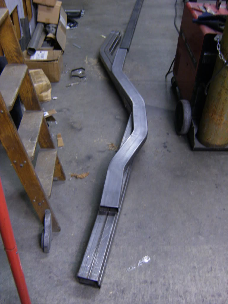
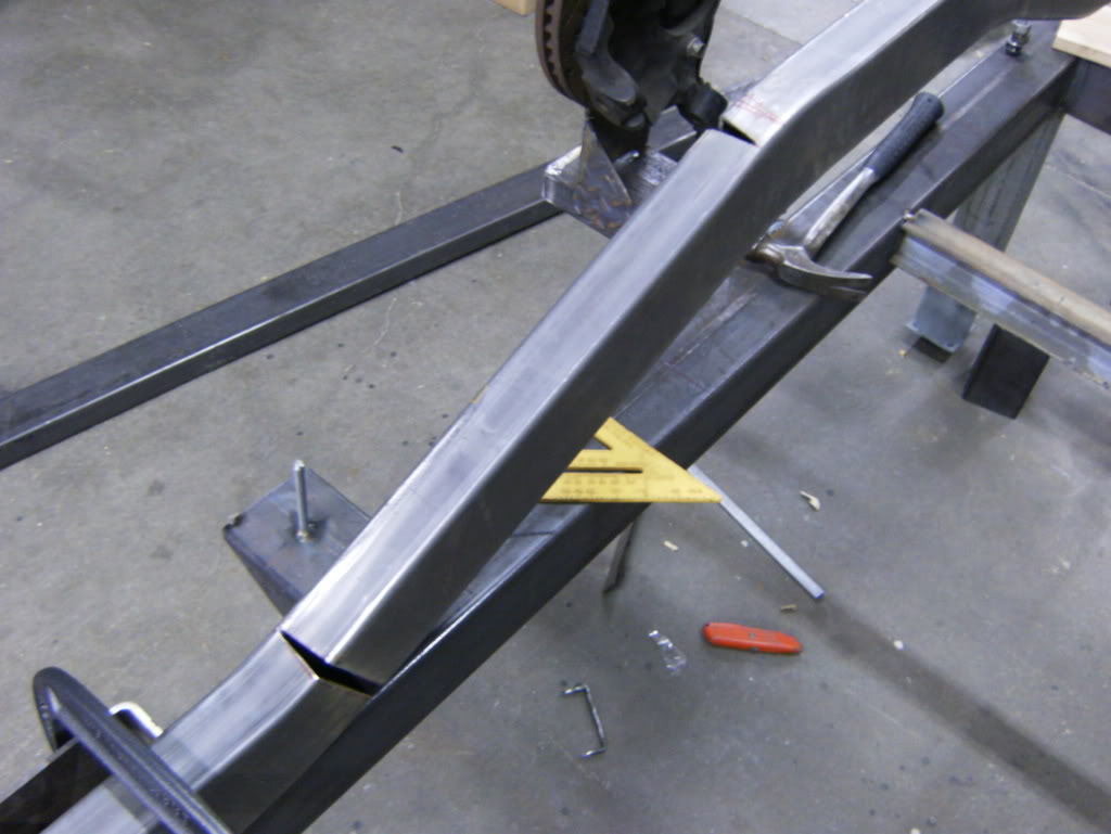
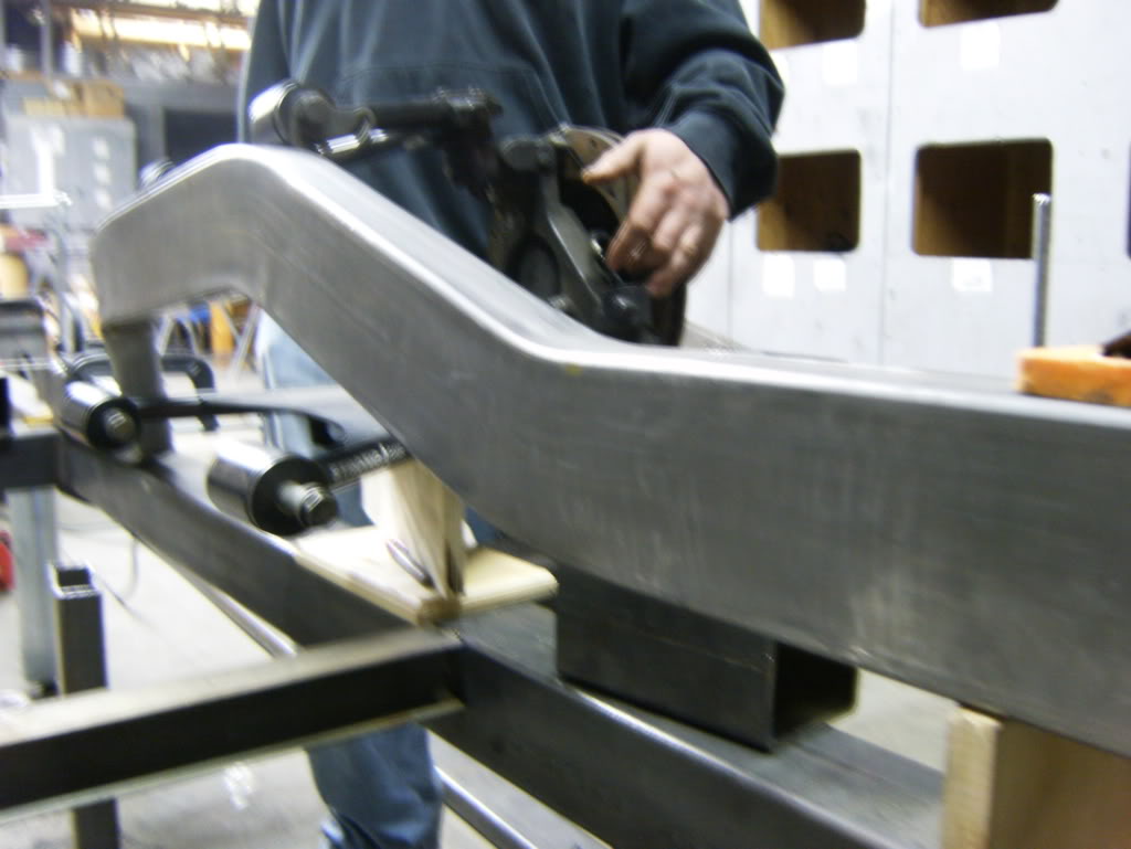
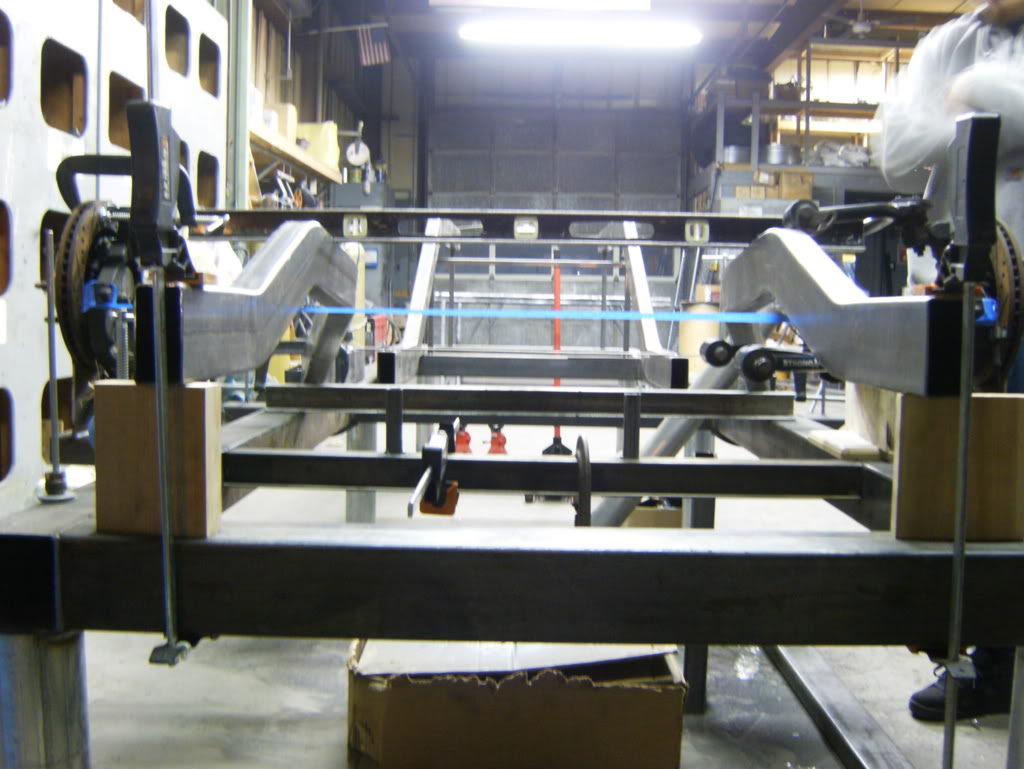
Well the frame rails are in, when mandrel bending it's impossible to put two different bends in one place so I could either A) piece the bend together or B) pie cut and bend the rails in and lay a nice strong bead down the side. I took the B) method. I plan to put a plate on the inner side for added strength.
Here is the stock frame showing how it kicks in and up at the same time.
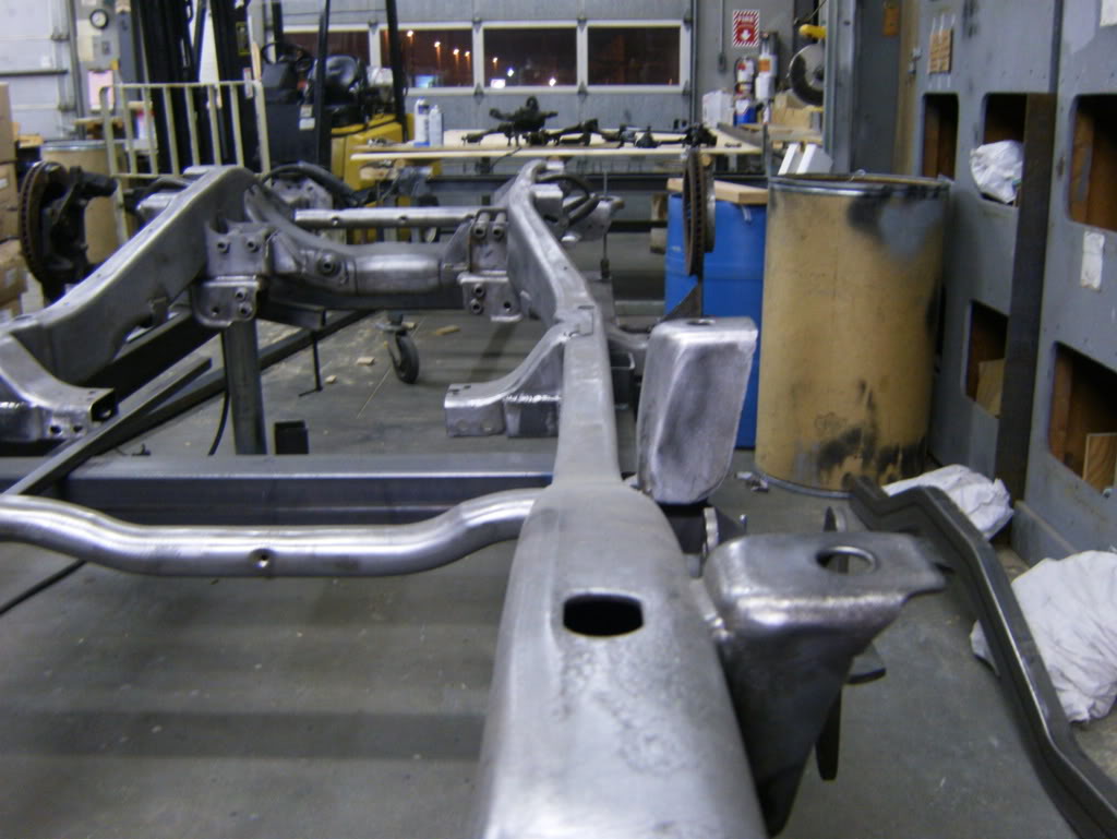
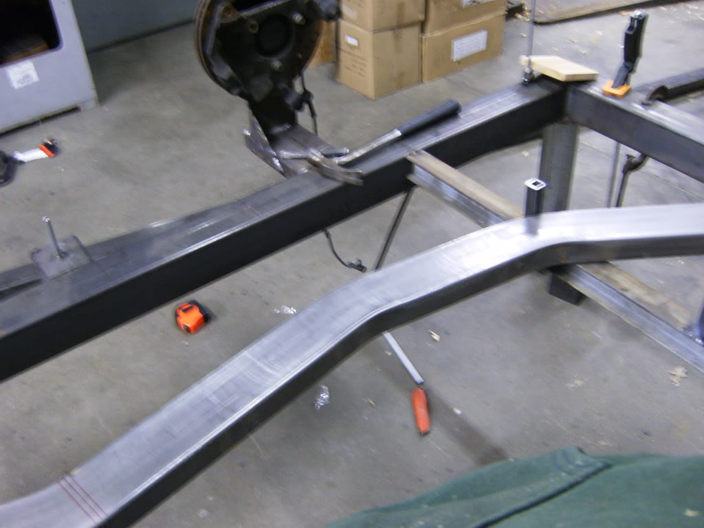
The frame rails, had them custom bent at AutoWeld Chassis
Laid out on my jig, the rear frame rails lift up a little high, I wrote down the wrong measurement on the plans, but its not way off, and in all actuality it worked out for the better because a design change I made showed it was necessary
Marking the pie cuts
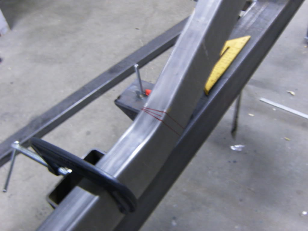
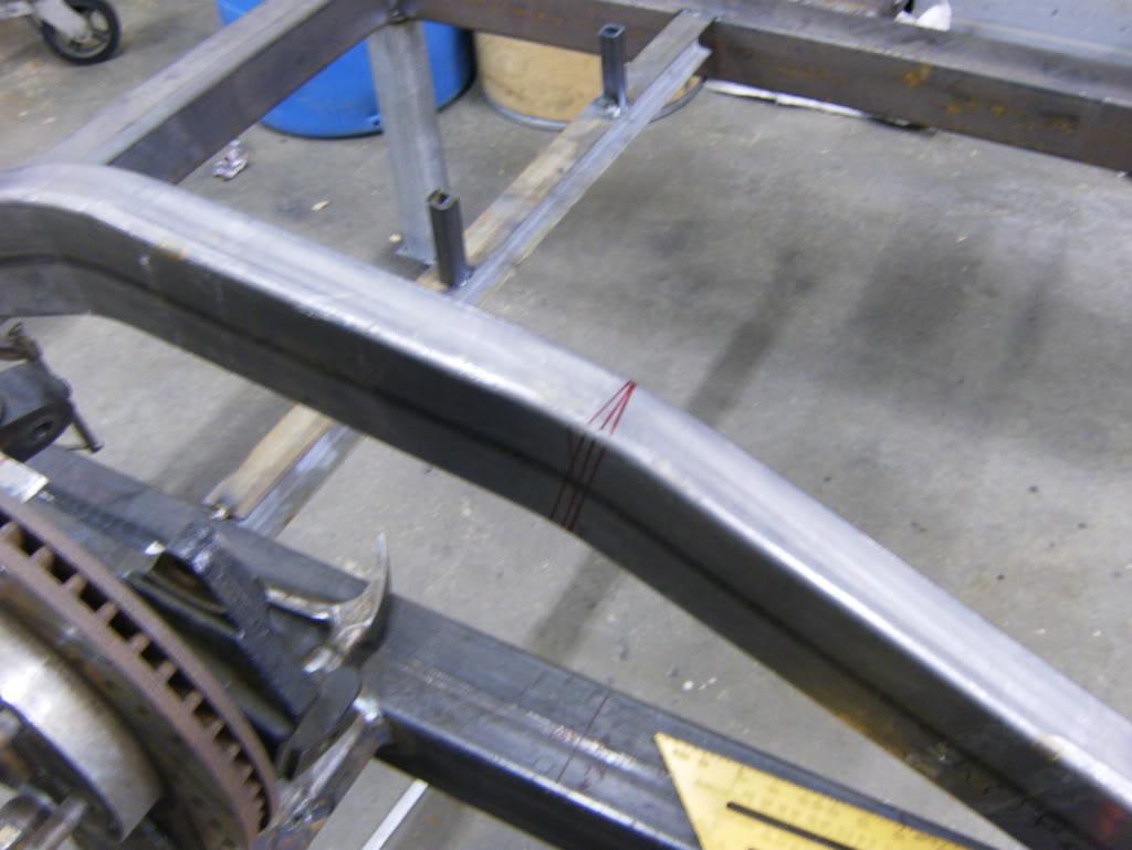
Cut and put back into place
Bent in and clamped firmly in place
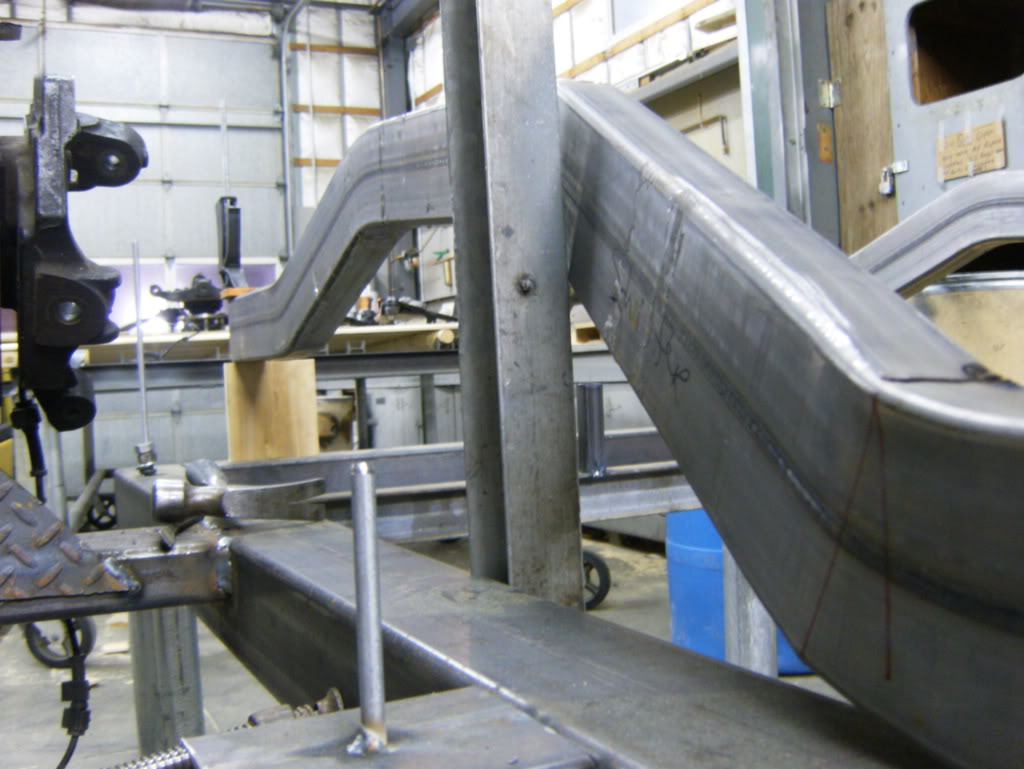
then welded up
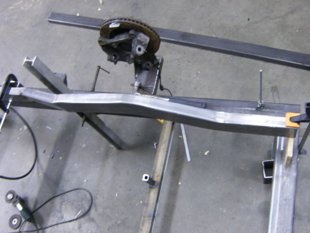
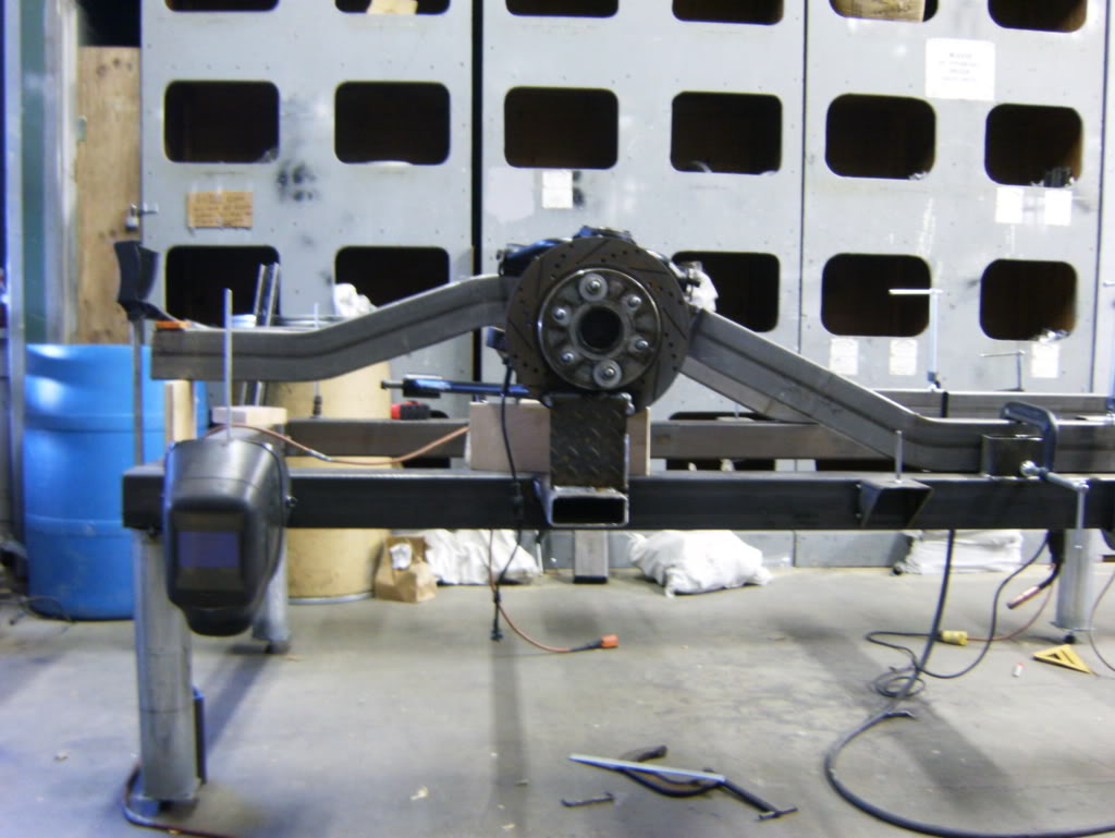
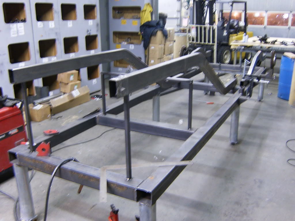
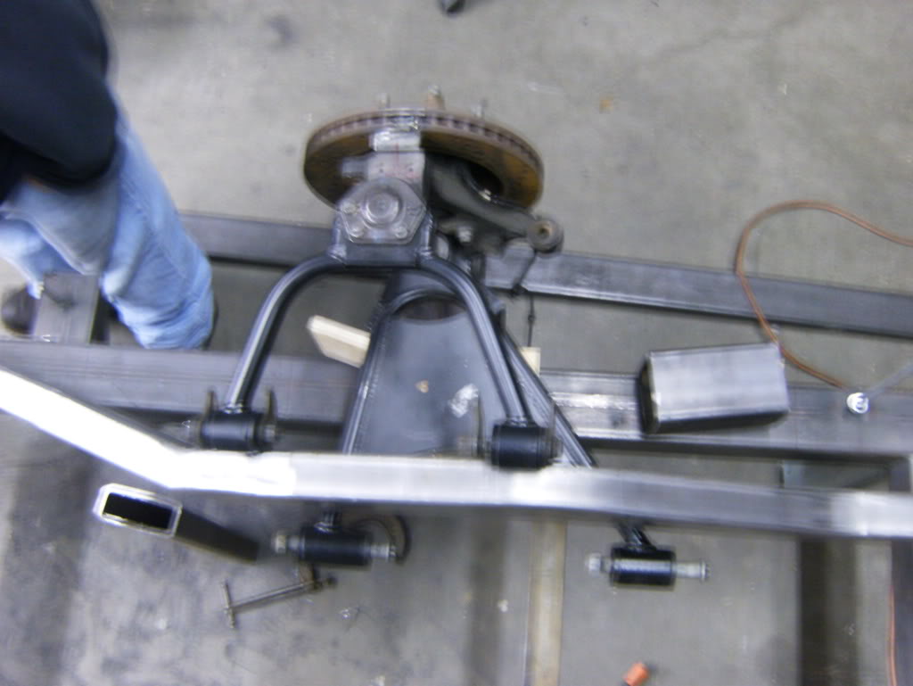
Then I put the arm up and in "basic position" to plan and see how stuff was going to work.
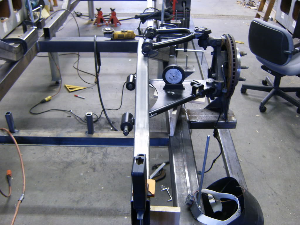
Lowers parallel uppers 10* pitch backwards

Here is the stock frame showing how it kicks in and up at the same time.
The frame rails, had them custom bent at AutoWeld Chassis
Laid out on my jig, the rear frame rails lift up a little high, I wrote down the wrong measurement on the plans, but its not way off, and in all actuality it worked out for the better because a design change I made showed it was necessary
Marking the pie cuts
Cut and put back into place
Bent in and clamped firmly in place
then welded up
Then I put the arm up and in "basic position" to plan and see how stuff was going to work.
Lowers parallel uppers 10* pitch backwards
Apr 6, 2008 | 12:09 PM
#326
Thread Starter
TECH Fanatic
iTrader: (12)
Joined: Mar 2005
Posts: 1,513
Likes: 6
From: Massachussetts
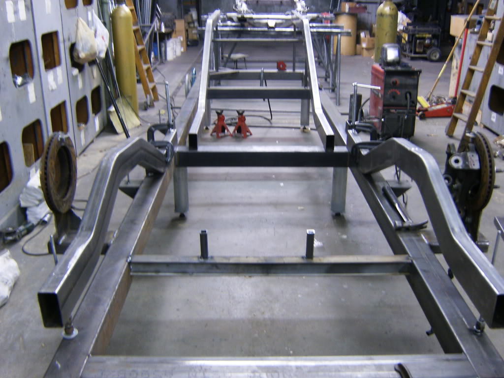
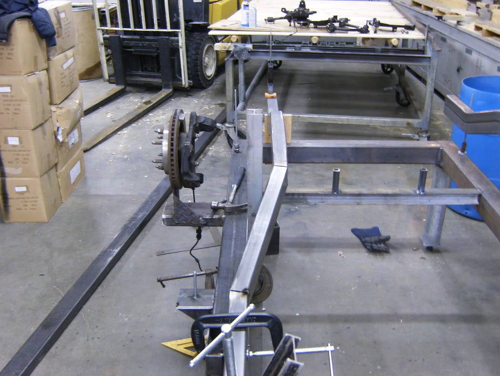
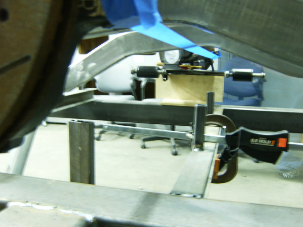
Now he is my current dilemma, my controls get raised and my rack can't be because the motor is right above it. So I plan to flip the tie rods then convert to a heims link, but I still don't think it's going to get low enough to where my lca angles will be parallel with my tie rod arms... we shall see, worst come to work I will lower my control arm slightly.
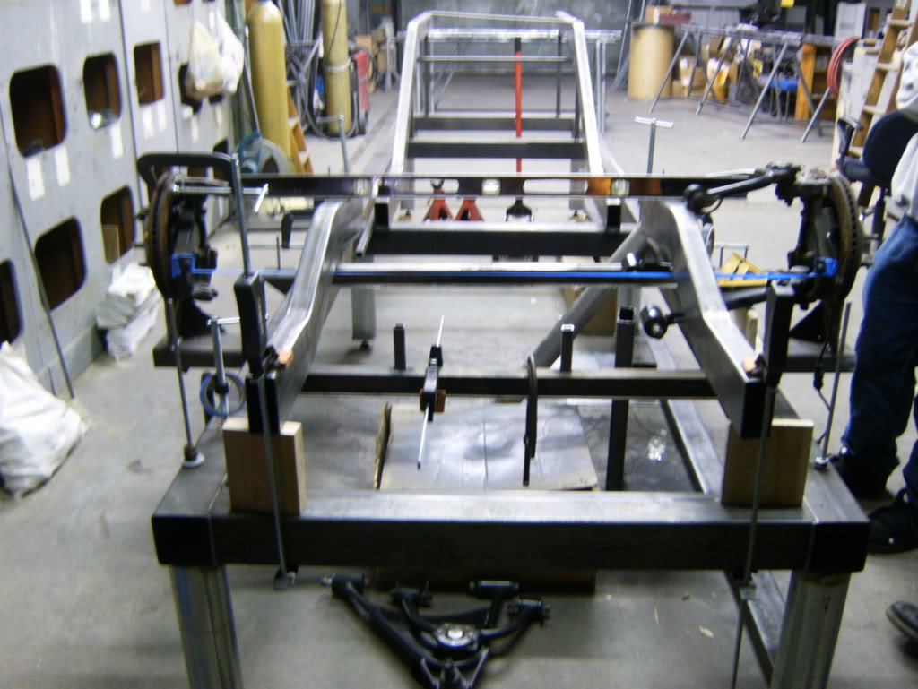
Now the two pieces of 1x1 represent the bottom of the bolts holes for the rack so say 2-3" above that the rack rests.
Now the two pieces of 1x1 represent the bottom of the bolts holes for the rack so say 2-3" above that the rack rests.


 Apr 6, 2008 | 09:07 PM
#330

I am amazed at all the work you are putting out GMracer! Very impressive. It's good to see another board member getting hands on and still taking time to share with us
What was your main reasoning to ditch the origional frame and go with the new design?
What was your main reasoning to ditch the origional frame and go with the new design?