2001 Frame up build


 Keep it up!
 Mar 27, 2008 | 03:18 PM
#307
Thread Starter
TECH Fanatic
iTrader: (12)
Joined: Mar 2005
Posts: 1,513
Likes: 6
From: Massachussetts
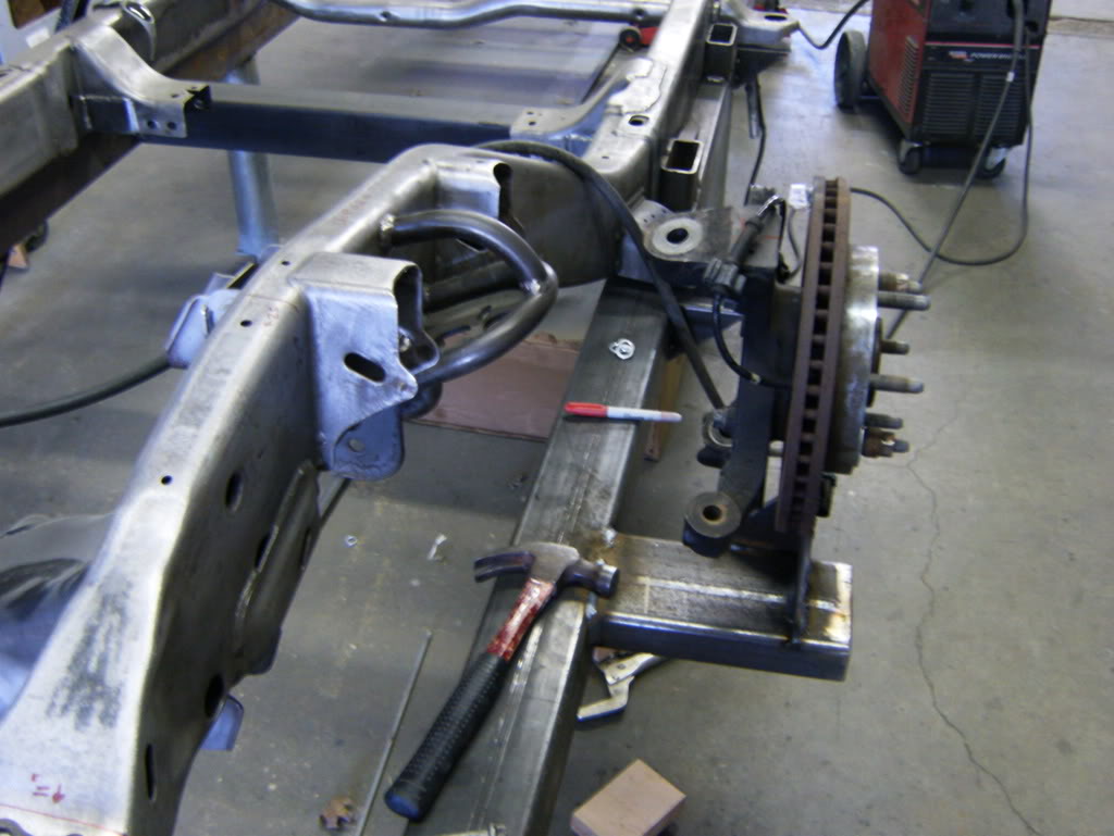
worked on it this past weekend.
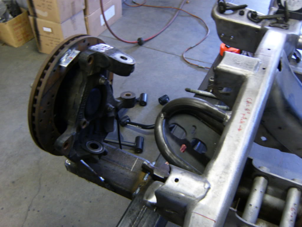
used my old rotors for a jig to set the hubs at ride height

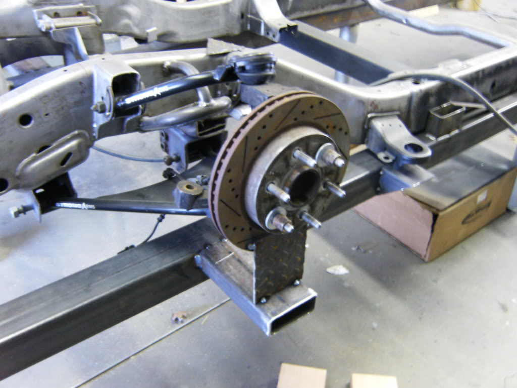
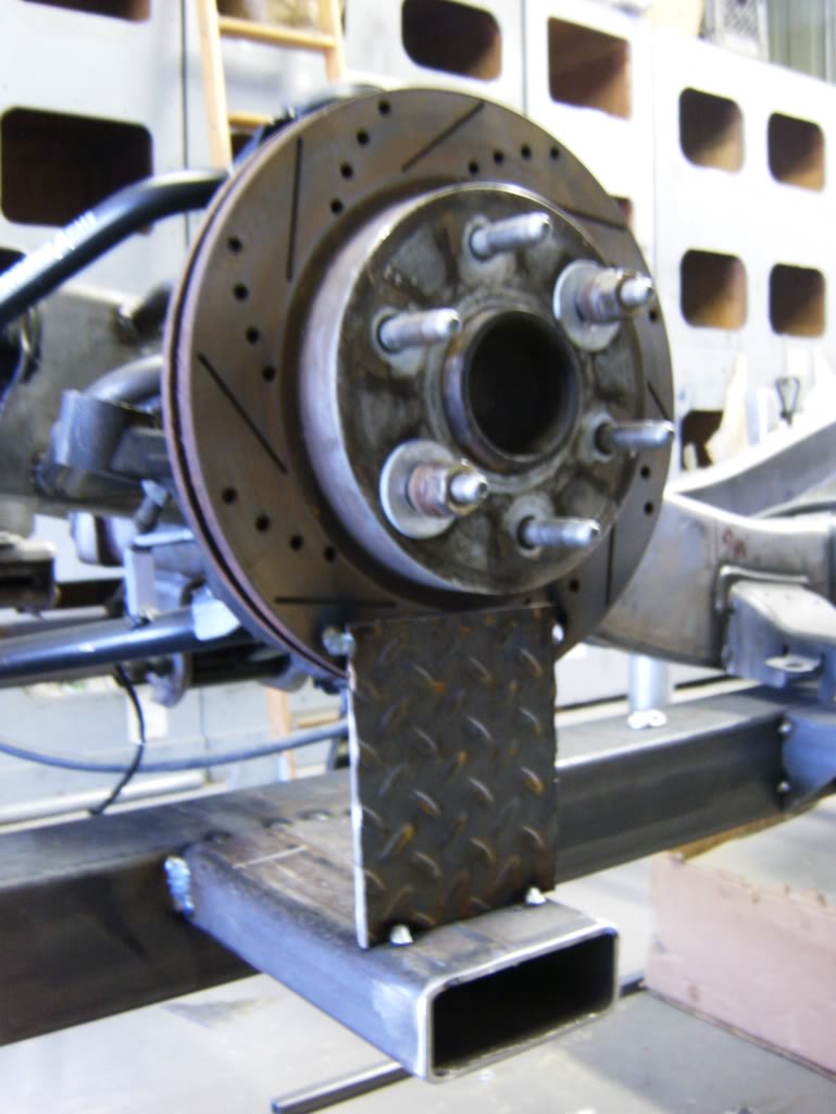
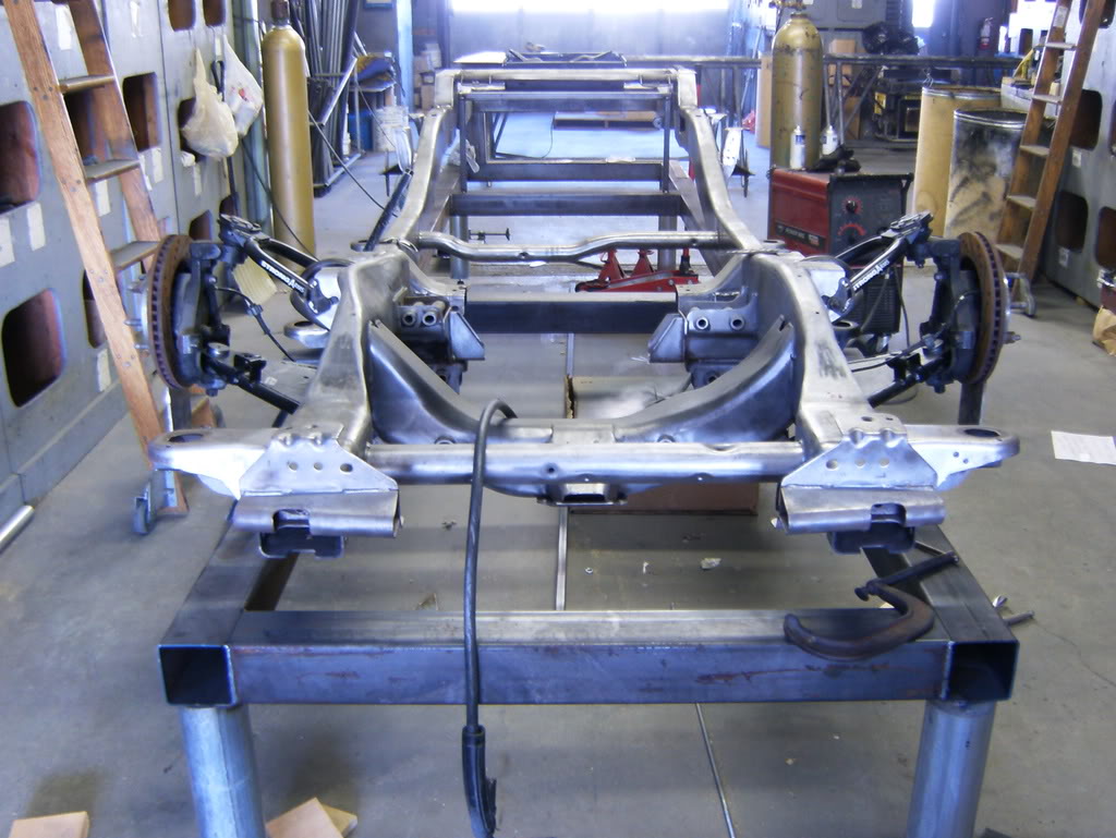
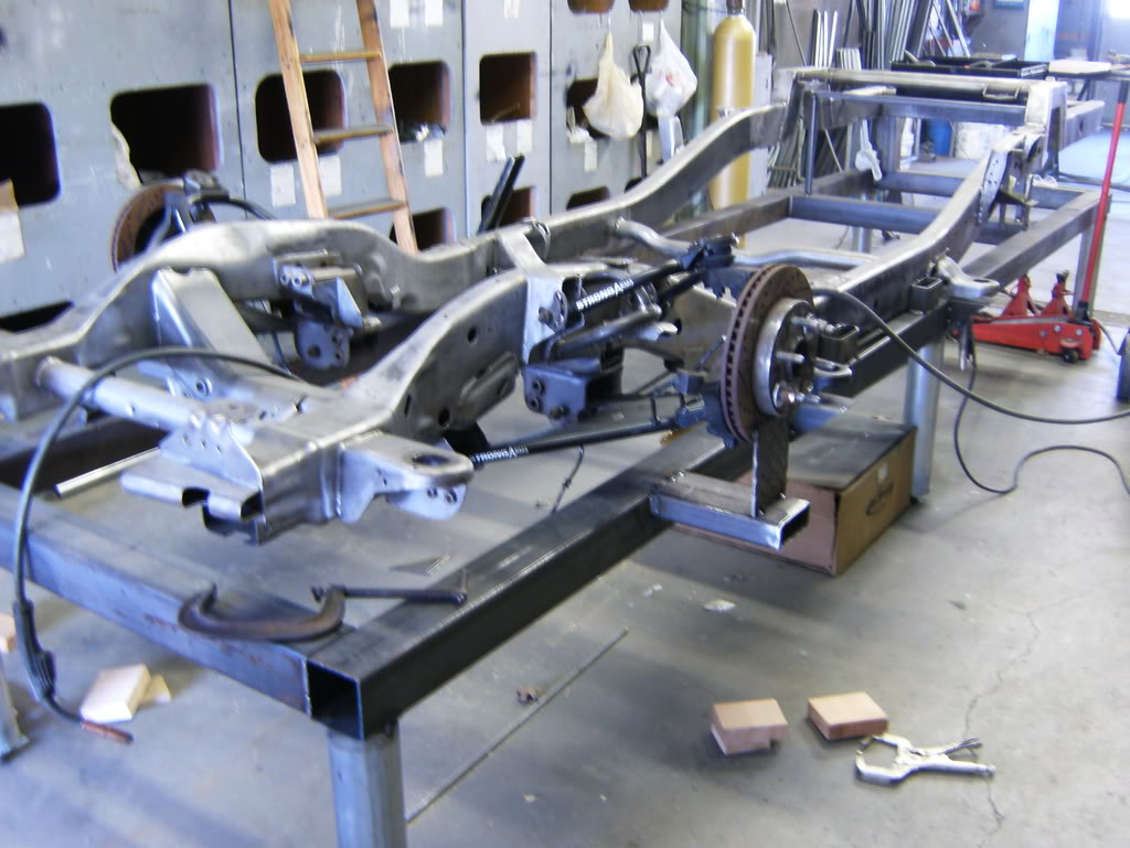
Now this right here is why I'm running the new frame, at ride height I want my control arms to be on a better path than this,

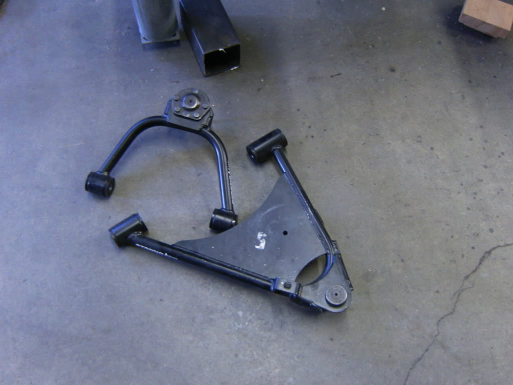
So I took some measurements and found the angles, took the arms off since the frame will be coming off the table soon
and I went over to the drawing board, or my plywood and maybe a full scale model of how the controls arms are setup
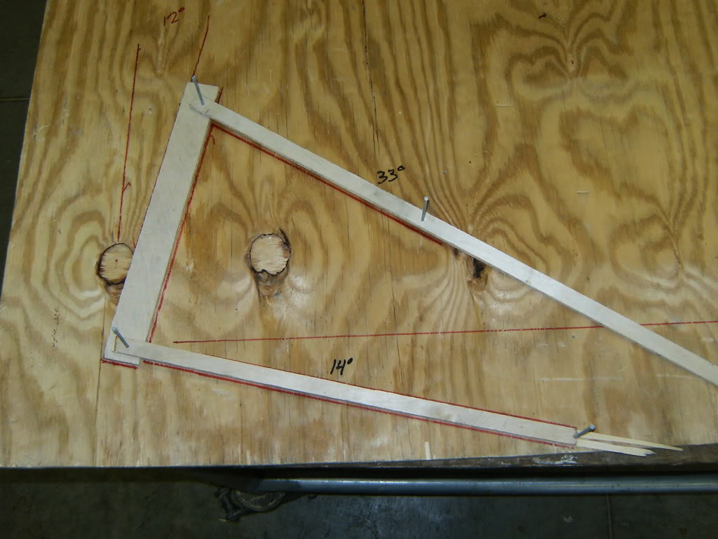
Above is how they are currently setup, 14* on the lca and 33* on the upper, YIKES :insane: The left is the spindle and the right are the pivot points on the frame.
I will leave the spindle side alone, which means it will look like this
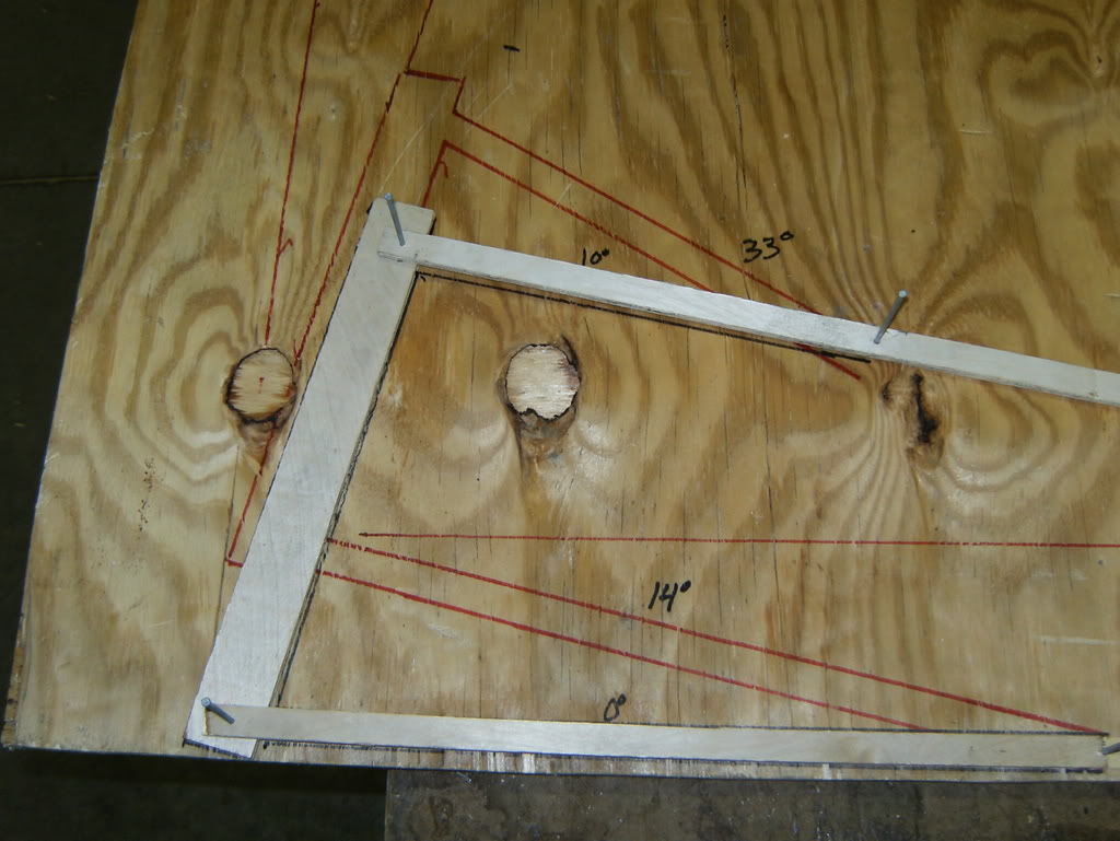
which is what stock arms are setup at, lca 0* and upper 10* (I believe)
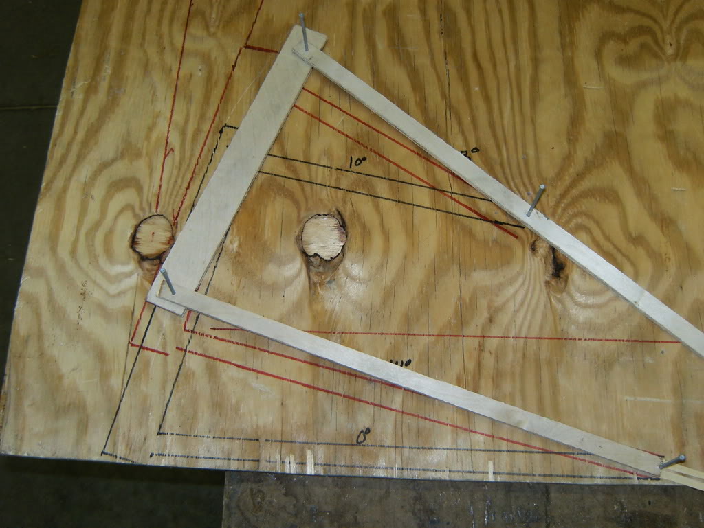
So the control arms have to be raised a little over 2" both lower and upper, and I plan to flip the tierod also, and I will make sure to set it up so the tierod is on the same plane as the lower so say if when I flip it, it changes the height 2.25" and the arms need to go up 2.5" I will sacrifice that .25" and raise them only 2.25"
This represents it fully laid out, with 9* negative camber
here is a video explaining what I just explained above

used my old rotors for a jig to set the hubs at ride height
Now this right here is why I'm running the new frame, at ride height I want my control arms to be on a better path than this,
So I took some measurements and found the angles, took the arms off since the frame will be coming off the table soon
and I went over to the drawing board, or my plywood and maybe a full scale model of how the controls arms are setup
Above is how they are currently setup, 14* on the lca and 33* on the upper, YIKES :insane: The left is the spindle and the right are the pivot points on the frame.
I will leave the spindle side alone, which means it will look like this
which is what stock arms are setup at, lca 0* and upper 10* (I believe)
So the control arms have to be raised a little over 2" both lower and upper, and I plan to flip the tierod also, and I will make sure to set it up so the tierod is on the same plane as the lower so say if when I flip it, it changes the height 2.25" and the arms need to go up 2.5" I will sacrifice that .25" and raise them only 2.25"
This represents it fully laid out, with 9* negative camber
here is a video explaining what I just explained above
Mar 27, 2008 | 03:38 PM
#308


Damn... If only I knew you were going to mock up the suspension in that fasion, I could have made you some plates that you could have bolted on to the rotor or even the spindle for that mater. I could have used some of them fancy crossdrilled and slotted rotors...