
Some disgusting pics
 Jul 22, 2015 | 09:48 AM
#31

What im wondering is if the rings butted and hurt the cylinder walls. The hurt walls caused excessive blowby, and contributed to pushing oil down the guides. That could have been why you were getting the rear of the valve cover gaskets leaking and the dipstick pushing out. I'm not certain about this, but it is what I was thinking.
Jul 22, 2015 | 03:09 PM
#32
Had the ID1000 injectors flow tested...looks like they didn't appreciate being cleaned. The automated test is a gradual ramp up.
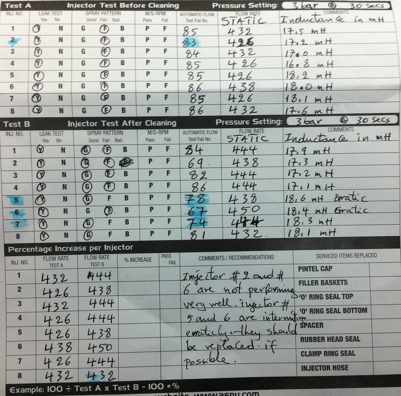
So static(max) flow rates for the ID1000s were:
Initial/After 2 cleaning cycles
1. 864/888cc/min
2. 852/876cc/min
3. 864/888cc/min
4. 852/888cc/min
5. 852/876cc/min
6. 876/900cc/min
7. 852/888cc/min
8. 864/864cc/min
With 2 and 6 being erratic. Not sure why #3 was clean as a whistle(see pics) compared to all the rest. Wiring checks out good to all injectors.
What I had noticed was that bank 2 would tend to go way lean on a heat-soaked idle. Cold testing doesn't tell me how the injectors behave at higher temps.
Last edited by DrX; Jul 22, 2015 at 07:16 PM.
 Jul 23, 2015 | 08:39 AM
#34


Joined: Jan 2006
Posts: 16,282
Likes: 438
From: Huntsville, AL
^ certainly could. Same physics applies in all engines. Oil in the chamber is bad.
Sounds like there are a lot of issues going on between engine assembly and fuel system. Oil problems from day screams machining/assembly problem. I am with George and think you should do a full tear down to see whats going on.
Throw you blower setup on a 4.8 and make 1200hp with twin roots superchargers
....it should last until you finish rebuilding the nice engine anyway!
Jul 23, 2015 | 10:47 AM
#35
^ certainly could. Same physics applies in all engines. Oil in the chamber is bad.
Sounds like there are a lot of issues going on between engine assembly and fuel system. Oil problems from day screams machining/assembly problem. I am with George and think you should do a full tear down to see whats going on.
Throw you blower setup on a 4.8 and make 1200hp with twin roots superchargers
....it should last until you finish rebuilding the nice engine anyway!
Sounds like there are a lot of issues going on between engine assembly and fuel system. Oil problems from day screams machining/assembly problem. I am with George and think you should do a full tear down to see whats going on.
Throw you blower setup on a 4.8 and make 1200hp with twin roots superchargers
....it should last until you finish rebuilding the nice engine anyway!
Red hot carbon and loose chunks of carbon flying around aren't good!
Definitely seems like it has always been pressurizing the crankcase.
 Jul 23, 2015 | 11:47 AM
#37

 Jul 23, 2015 | 01:34 PM
#39
