
Anybody got 02 Serivce manual with Schematics?
 Nov 3, 2006 | 05:07 PM
#1

I need the foot pedal to TAC module circuit scanned and either posted or emailed to me or both... purdy please? 
Thanks,
Bill
billreid1@***.net
Thanks,
Bill
billreid1@***.net
Nov 3, 2006 | 10:33 PM
#2

Email sent.
I was was just comparing the 02/04/LS2 circuits again the other day. Noticed that a couple of pins from the APP sensors to the TAC module are switched around between the 02 and 04 but the 02 TAC still works on the 04s. APP sensor voltages are supposed to move in the same direction on the 04s but having the high/low ref pins switced around for one of the circuits means that one moves up while the other moves down, which is what an 02 TAC module expects. How lucky was that! The funny thing is that the voltage ranges are supposed to be different on 02s and 04s but it still works?? So now I am wondering if the same can be done with the TP Sensor outputs from the LS2 TB. i.e go back to my 04 TAC module(PCM might be happier with that) but crack open the LS2 TB and separate the high/low reference circuits to the two TPSensors so that they both move in the same direction as expected by an 04 TAC module. Again, the voltage ranges are supposed to be different, but if the 04 APP sensors worked with the 02 TAC module, then perhaps the LS2 TPsensor outputs will also work with the 04 TAC module. I think that the TAC module is supposed to be able to learn the voltage range anyway because it does not always remain constant. Anybody ever crack one of these TBs open?
I was was just comparing the 02/04/LS2 circuits again the other day. Noticed that a couple of pins from the APP sensors to the TAC module are switched around between the 02 and 04 but the 02 TAC still works on the 04s. APP sensor voltages are supposed to move in the same direction on the 04s but having the high/low ref pins switced around for one of the circuits means that one moves up while the other moves down, which is what an 02 TAC module expects. How lucky was that! The funny thing is that the voltage ranges are supposed to be different on 02s and 04s but it still works?? So now I am wondering if the same can be done with the TP Sensor outputs from the LS2 TB. i.e go back to my 04 TAC module(PCM might be happier with that) but crack open the LS2 TB and separate the high/low reference circuits to the two TPSensors so that they both move in the same direction as expected by an 04 TAC module. Again, the voltage ranges are supposed to be different, but if the 04 APP sensors worked with the 02 TAC module, then perhaps the LS2 TPsensor outputs will also work with the 04 TAC module. I think that the TAC module is supposed to be able to learn the voltage range anyway because it does not always remain constant. Anybody ever crack one of these TBs open?
Last edited by DrX; Nov 3, 2006 at 10:40 PM.
Nov 3, 2006 | 11:25 PM
#3
Thanks Dr X
Obviously you must know what I am trying to do
The 02 TAC input shows 3 APP sensor signals... The 06 only has 2. Does the 04 only have 2?
TP sensors for the 06 TB shows the same resistor configuration (placement in the circuit)... but obviously different from the 02. The 02 TB TP sensor(s) layout shows the same sensor resistor configuration as the 02 TAC APP 1 & 2.
I have an LS2 TB sitting around collecting dust
Bill
Nov 3, 2006 | 11:57 PM
#4
Originally Posted by billreid1@***.net
Thanks Dr X
Obviously you must know what I am trying to do
The 02 TAC input shows 3 APP sensor signals... The 06 only has 2. Does the 04 only have 2?
TP sensors for the 06 TB shows the same resistor configuration (placement in the circuit)... but obviously different from the 02. The 02 TB TP sensor(s) layout shows the same sensor resistor configuration as the 02 TAC APP 1 & 2.
I have an LS2 TB sitting around collecting dust
Bill
Obviously you must know what I am trying to do
The 02 TAC input shows 3 APP sensor signals... The 06 only has 2. Does the 04 only have 2?
TP sensors for the 06 TB shows the same resistor configuration (placement in the circuit)... but obviously different from the 02. The 02 TB TP sensor(s) layout shows the same sensor resistor configuration as the 02 TAC APP 1 & 2.
I have an LS2 TB sitting around collecting dust
Bill
Nov 4, 2006 | 03:52 PM
#5
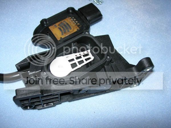
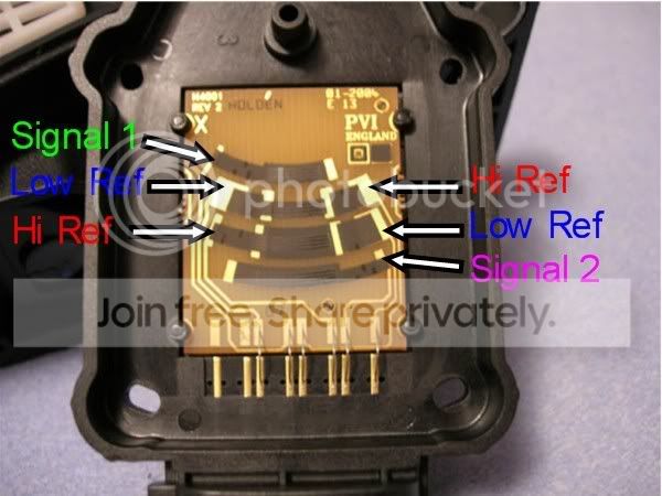
Here's a little more for you to work with. Found some pics of a cracked LS2 APP Sensor. I added the labels for illustrative purposes only. Hi/Low refs and sensor #s could be switched around. I would imagine that the inside of the TB's TP sensor would be similar other than the common hi/low ref circuits in the LS2 TPS. Looks like there is a section of predetermined fixed resistance at one end of each variable resistor/potentiometer. Each sensor also has a different amount of sweep due to the different positions on the arm. These could be part of the differences between a 78mm and 90mm LS2 TB that results in the limiting of max throttle opening to around 85%.

Last edited by DrX; Nov 5, 2006 at 09:23 AM.
Nov 4, 2006 | 04:54 PM
#6
Thanks DrX... right click / save as...time to do some studying.
I would also like to thank Grumpy4.8... for shooting me some emails. Between you 2 guys I have plenty of info to digest now.
Bill
I would also like to thank Grumpy4.8... for shooting me some emails. Between you 2 guys I have plenty of info to digest now.
Bill
Last edited by billreid1@cox.net; Nov 4, 2006 at 05:54 PM.
Nov 4, 2006 | 05:54 PM
#7
Originally Posted by DrX
Schematics show 3 APP sensors in the 04s. Same as 02s except for the wiring. But "Description and Operation " only mentions 2 sensors for 04s?? I'd say there are 3, as opposed to 2 in the LS2s. Do the 06 trucks have a separate TAC module? Wouldn't mind seeing any 06 schematics that you may have.
... edit... now that I think about it... I wonder if one of Nick Williams 90mm C5 Corvette throttle body's might work with the 02 TAC. I think the TB motor would hit the side of the Maggie case. But if he flipped the (3) bolt pattern in the CNC program... hmm... or add the 4 bolt LS2 pattern... more thought on that. I have him scoping another solution as well...
Bill
Last edited by billreid1@cox.net; Nov 4, 2006 at 06:07 PM.
Trending Topics


Thread
Thread Starter
Forum
Replies
Last Post
drummer0415
GMT 900 Trucks General Discussion
11
Oct 24, 2015 08:16 PM
91LT16SpeedFormula
GM Parts Classifieds
12
Oct 17, 2015 08:01 PM
TAPyvehc93
FORCED INDUCTION
1
Sep 12, 2015 08:19 PM