


Finally the real problem!
 Dec 5, 2007 | 12:36 PM
#1

Thread Starter
Launching!
Joined: Apr 2007
Posts: 276
Likes: 0
From: Utah
 Finally the real problem!
I finally got my truck to a local tunner. For those of you that remember I had a back two lean code that others had told me was a programming issue since all the mechanicals like leaks had been checked.
Well as it turns out that the custom harness made for the truck is the trouble. Basically the sensor is fine, we swapped it to the other side to check that. and we get 12 volts to the sensor testing from the plug. Up at the computer side of things we get 70 millivolts all the time on the high signal when it should be between 700 and 800. Also we only get 2 volts and when we test the other (working) O2 sensor we get a full 12 volts to the computer.
I don't know electrical very well. I was going to check to see that the right wire runs from the sensor up to the computer to be sure a wire didn't get crossed somewhere? I think the sensor should be heating up ok since 12 volts are getting to the sensor. But I don't now alot about it or how the system works.
Any suggestions or tutorials as to where to go from here. The harness was made in Florida and sent to me here in Utah. I would really hate to have to pull the harness and send it back and have misgivings as to how well it would get fixed anyway since an number of other things were wired wrong.
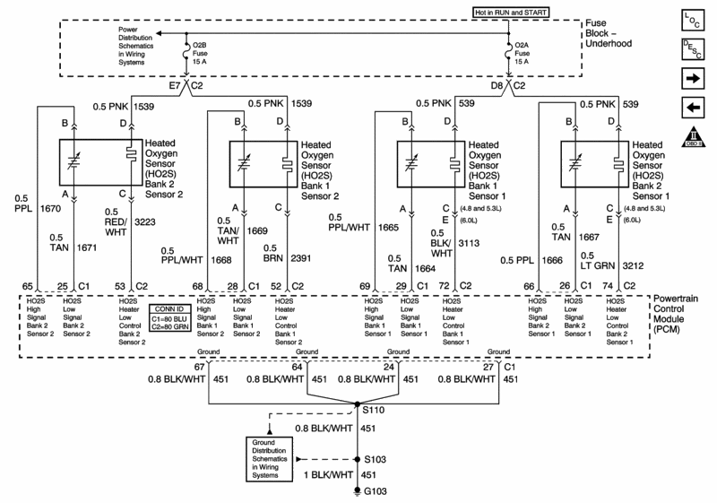
If anyone has the wire diagrams for an 04 LQ4 02 stuff that they could send or post that would be good also.
Thanks as always, you guys are great!
Well as it turns out that the custom harness made for the truck is the trouble. Basically the sensor is fine, we swapped it to the other side to check that. and we get 12 volts to the sensor testing from the plug. Up at the computer side of things we get 70 millivolts all the time on the high signal when it should be between 700 and 800. Also we only get 2 volts and when we test the other (working) O2 sensor we get a full 12 volts to the computer.
I don't know electrical very well. I was going to check to see that the right wire runs from the sensor up to the computer to be sure a wire didn't get crossed somewhere? I think the sensor should be heating up ok since 12 volts are getting to the sensor. But I don't now alot about it or how the system works.
Any suggestions or tutorials as to where to go from here. The harness was made in Florida and sent to me here in Utah. I would really hate to have to pull the harness and send it back and have misgivings as to how well it would get fixed anyway since an number of other things were wired wrong.
If anyone has the wire diagrams for an 04 LQ4 02 stuff that they could send or post that would be good also.
Thanks as always, you guys are great!


 Dec 5, 2007 | 08:31 PM
#4

To guarantee a proper fix you could always eliminate the suspect wiring to the O2 sensor and run your own, using the above schematic as your guide. Clip the wires back far enough from both the sensor and PCM to give you room to attach the new wire(s), get some black loom covering (a couple bucks at AutoZone), and run the same gauge wiring.
Since you mentioned 12v, I'm assuming that the problem is with the sensor heater, as the sensor itself doesn't generate voltage that high.
Since you mentioned 12v, I'm assuming that the problem is with the sensor heater, as the sensor itself doesn't generate voltage that high.
Dec 6, 2007 | 01:10 PM
#5
Thread Starter
Launching!
Joined: Apr 2007
Posts: 276
Likes: 0
From: Utah
So if I am understanding you guys and blending that with info I am getting the green wire in plug 74 should read at 12 volts rather than 2 and so it is likely that this is the wire with the short. I was thinking that I would for starters test this wire for connectivity, make sure the pins are ok and then likely, just as you have said run a new wire from the o2 sensor up to the pcm wire and start there.
have I missed anything?
have I missed anything?
Dec 6, 2007 | 03:52 PM
#6
So if I am understanding you guys and blending that with info I am getting the green wire in plug 74 should read at 12 volts rather than 2 and so it is likely that this is the wire with the short. I was thinking that I would for starters test this wire for connectivity, make sure the pins are ok and then likely, just as you have said run a new wire from the o2 sensor up to the pcm wire and start there.
have I missed anything?
have I missed anything?
You're on the right track, almost there...
Dec 6, 2007 | 07:28 PM
#7
Are you testing with the key on or the engine running? With the key on you should see the 12v at pin 74, that is supplied via the underhood fuse block, through the 15A O2A fuse. With the engine running and the heater activated, you should see 0 volts at pin 74 and 12V if you put the meter leads across pins D to C of the B2 S1, as the heater should be using the 12v to do it's job. If you're not seeing 12V, than the voltage is dropping elsewhere, such as resistance in the wire from an open circuit or it's shorting to another wire and traveling elsewhere.
You're on the right track, almost there...
You're on the right track, almost there...

let me know if you need the diagnosis flow chart for this or any other diagrams!!
Trending Topics
Dec 7, 2007 | 11:16 AM
#8
Thread Starter
Launching!
Joined: Apr 2007
Posts: 276
Likes: 0
From: Utah
Dec 9, 2007 | 07:26 PM
#9

A "short" to ground blows a fuse. That's zero volts, not 2 or 12vdc. You have two circuits on the O2 sensors. You have the sense line(needed) and the heater circuit(not really needed) which only functions for the first couple of minutes when the engine is cold. After that the heater is useless. Do you need the heater circuit? GM wants you to go into closed loop quicker, but that's questionable. The sense line on your O2s should be constantly switching above and below 450mVdc as the PCM tries to maintain the EPA regulated 14.7AFR not staying near 700mV unless your at WOT which isn't the case. Time to get out the DVOM, some alligator clips and straight pins(to do backprobing) and do some troubleshooting with a schematic.
Dec 9, 2007 | 10:35 PM
#10

Launching!
Joined: Oct 2004
Posts: 247
Likes: 0
From: Houston
i myself have an o2 problem. the connector got destroyed by the header so i replaced the connector and wired it up wrong - i had A and D mixed up and becuase of that it would blow the fuse instantly. after realizing what i had done i corrected it and now it still says no activity B1 S2... and i know the sensor is good becuase i switched the 2 front ones and it still said B1 S2. im 99% sure i have the other 2 wires wired in correctly but maybe not. if its wired correctly what is the next step? test for continuity from the connector to the PCM?
clint
clint

