
Old style fuel pump voltage booster install ??
 Mar 7, 2006 | 10:03 PM
#1

Thread Starter
Destroyer of Transmissions
iTrader: (28)
Joined: Feb 2005
Posts: 4,962
Likes: 1
From: Orlando, FL
This unit is actually an early Magnuson unit but I think it is pretty much the same as the Kenne bell. Anyway.....
I just want somebody who knows how to install a boost a pump to look at my wiring diagram. Both reds go into the Hobbs switch so that it completes the circuit when it closes (which is 3psi for this switch), am I right? The black is a ground that I will most likely strap to the firewall or possibly the Alt if it looks better. Connect the other wires to the pump, Then I just "T" into the vacuum line that the FPR is connected to and I'm in business? How do I feed power to the unit in the first place? Splice it into one of the red wires from the battery or alt? If anybody has instructions let me see.


__________________
 Mar 8, 2006 | 10:34 AM
#3

TECH Addict
Joined: Feb 2004
Posts: 2,120
Likes: 0
OK here goes my guess.
The long wire you have running to the pump goes to the Hoobs switch to activate the booster unit.
The red wire with the inline fuse goes to a power source that is preferably switched with the ignition on engine running so that there is no way the pump can be switched when the engine is not running. Maybe this is not important and you can run it to stud 1 or 2 in the under hood power panel. If you use stud 1 make sure it has been fused. Mine was not fused from the factory and I had to fuse it when I added my trailer brake control.
The black wire with the loop connector on the end goes to a chassis ground. The control unit acts as a relay as well as the power booster.
The other red wire goes to the fuel pump to supply the higher voltage when boost is over 3 psi.
The fuel pump is already grounded and does not need another ground just a power wire to boost the voltage when required.


 Mar 9, 2006 | 09:54 AM
#6
TECH Addict
Joined: Feb 2004
Posts: 2,120
Likes: 0
That wiring schematic looks correct to me. I think you should take your power from the stud 2 post that you will find once you take the cover and inner plastic shroud off of the underhood fuse block. That should give you alternator voltage to send to the pump when the hoobs switch activates the voltage booster. I assume the stud 2 gets alternator voltage and that I am not making an *** of you and me.
Do not use the grey fuel pump switch wire with this booster kit. The grey wire is meant as a switch wire only and not as a power wire for the fuel pump. If you use the grey wire you must run it to switch a relay which will then supply power to the voltage booster. You can add a relay to your set up if you wish and then it will only be activated when the fuel pump is activated. This would add a little safety to your booster. Are you sure that you have the whole kit and that you are not missing a relay? The inline fuse in the red power wire would seem to indicate that it is meant to go straight to a power source and not through a relay.
You can test your install be hooking it all up except the wire to the fuel pump. Using a test light check for power to the red fuel pump wire. At no time should this lead be hot unless the hoobs switch is activated. You can test operation of the booster by jumping the leads to the hoobs switch together and you should get power at the red fuel pump wire. If it checks out OK then connect the wire to the hot lead on your fuel pump and you should be on your way. The booster unit should have diodes or something in it to keep the power from backfeeding through it from the fuel pump. Once the fuel pump is connected to the booster you can test it by jumping the wires to the hoobs switch together or by jumping accross the leads to the hoobs switch with the wires attached to it and the fuel pump should be activated at high speed.
If you can hear the fuel pump go to high speed when the booster is activated then you will know at what boost level it is coming on. If you can't hear it you may be able to run a wire from the cold side of the hoobs switch through a lighted diode to ground in the cab somewhere you can see it. It should light when the hoobs switch is activating the circuit. I am not sure how much power the booster puts through the hoobs switch but you can test it with a voltmeter. It should be enough to power a small bulb.
Mar 9, 2006 | 06:46 PM
#7
Thread Starter
Destroyer of Transmissions
iTrader: (28)
Joined: Feb 2005
Posts: 4,962
Likes: 1
From: Orlando, FL
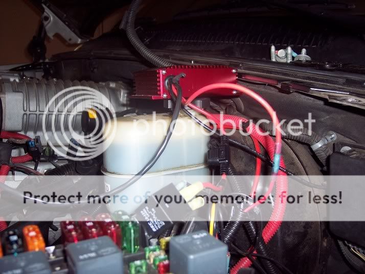
I talked to Blown364 today. He has done this install. He told me to disconnect the red wire from the RELAY that is already powering the inline pump. Cut the spade off that wire and connect it to the 12 gauge red wire on the boost a pump with the fuse. Next, take the smaller wire I just cut the spade off of (the red wire to the pump) and connect it to the other 12 gauge boost a pump red wire. Ground to ground, and connect the other two wires to the hobbs. Testing will begin in a few minutes. We are on a dinner break. Picture is hard to see. Let me know what you think...
Trending Topics
Mar 10, 2006 | 10:54 AM
#8
TECH Addict
Joined: Feb 2004
Posts: 2,120
Likes: 0
That all sounds really good to me. The boost-a-pump then supplies x-voltage to the fuel pump all the time switched by the grey fuel pump signal wire through the relay and supplies y-voltage (some higher amount ) when the hoobs switch triggers the boost-a-pump at 3 psi boost.
Good to hear that Blown364 knows how the booster is intended to work.
Any idea how the booster increases line voltage to the pump?
Good to hear that Blown364 knows how the booster is intended to work.
Any idea how the booster increases line voltage to the pump?

Thread
Thread Starter
Forum
Replies
Last Post
InsaneDomestics
Tuning, Diagnostics, Electronics, and Wiring
5
Jul 27, 2015 02:42 PM
Mossyoakglock
GMT 900 Trucks General Discussion
0
Jul 17, 2015 08:30 AM