
Schematics, Pinoouts, Training Materials, Technical Documents
 Feb 26, 2012 | 02:17 PM
#41


2007 GMT-900
Body Control System Description and Operation
The body control system consists of the body control module (BCM), communications, and various input and outputs. Some inputs, outputs and messages require other modules to interact with the BCM. The BCM also has discrete input and output terminals to control the vehicle's body functions. The BCM is wired to the GMLAN high speed serial data buss and the GMLAN low speed serial data buss and acts as a gateway between them. If the BCM does not communicate the vehicle will not start due to the inability of the engine control module (ECM)/powertrain control module (PCM) and theft deterrent module (TDM) to communicate without the BCM providing the gateway function.
Power Mode Master
This vehicles body control module (BCM) functions as the power mode master (PMM). The ignition switch is a low current switch with multiple discrete ignition switch signals to the PMM for determination the power mode that will be sent over the serial data circuits to the other modules that need this information, and so the PMM will activate relays and other direct outputs of the PMM as needed. Refer to Power Mode Description and Operation for a complete description of power mode functions.
Serial Data Gateway
The body control module (BCM) in this vehicle functions as a gateway or translator. The purpose of the gateway is to translate serial data messages between the GMLAN high speed buss and the GMLAN low speed buss for communication between the various modules. The gateway will interact with each network according to that network's transmission protocol.
One example of this necessary communication is the communication between the engine control module (ECM)/powertrain control module (PCM) which is high speed serial data and Theft Deterrent Module which is low speed serial data. If these modules can not exchange information, the vehicle will not start.
Communication between the BCM and a scan tool can be on the high speed GMLAN network or low speed GMLAN network. If one network is lost, the BCM can still communicate with the scan tool. A lost communication DTC typically is set in modules other than the module with a communication failure.
Body Control Module
The various body control module (BCM) input and output circuits are described in the corresponding functional areas indicated on the BCM electrical schematics. Some BCM functions with the subsystems may be as a gateway only or as an enable for the system. The BCM related systems/subsystems include, but are not limited to the following:
- Antilock Brake System (ABS)�Refer to ABS Description and Operation .
- Automatic Day-Night Mirror�Refer to Automatic Day-Night Mirror Description and Operation .
- Cruise Control System�Refer to Cruise Control Description and Operation .
- Electrical Power Management (EPM)�Refer to Electrical Power Management Description and Operation .
- Exterior Lighting�Refer to Exterior Lighting Systems Description and Operation .
- Horn System�Refer to Horns System Description and Operation .
- HVAC�Refer to Air Delivery Description and Operation and Air Temperature Description and Operation .
- Instrument Cluster Indicator Control�Refer to Instrument Cluster Description and Operation .
- Interior Lighting�Refer to Interior Lighting Systems Description and Operation .
- Power Door Lock System�Refer to Power Door Locks Description and Operation .
- Rear Window Defogger System�Refer to Rear Window Defogger Description and Operation .
- Redundant Steering Wheel Controls�Refer to Steering Wheel Controls Description and Operation .
- Remote Function Actuation (RFA) Control�Refer to Keyless Entry System Description and Operation .
- Retained Accessory Power (RAP)�Refer to Retained Accessory Power Description and Operation .
- Shift Lock Control System�Refer to Automatic Transmission Shift Lock Control Description and Operation .
- Starting System�Refer to Starting System Description and Operation .
- Supplemental Inflatable Restraint (SIR) System�Refer to SIR System Description and Operation .
- Theft Deterrent�Refer to Content Theft Deterrent (CTD) Description and Operation .
- Tire Pressure Monitor (TPM) System�Refer to Tire Pressure Monitor Description and Operation .
- Wiper/Washer System Functions�Refer to Wiper/Washer System Description and Operation .
 I am Still trying to figure out all the systems tak to eacth other.
-The Interior Exterior Light system does not work
-I can not control the Light functions with a tech 2
-The Horn does not work
-I can not control the horn with a tech 2
-The Door lock system does not work
-The remote does not work.
-I can not control the door functions with a tech 2
-The shift interlock does not work. you can pull the gear selector down with out engaugeing the brake.
-The startering system does not function.
-I can sweep the Gauges and turn on all the indictor lights on the Instrument cluster with the Tech 2
-I can see the brake lamp switch open and close.
-When you pull down on the gear selector it does show that it is engaugeing a gear Just not which gear on the scan tool but It does not display it on the Instrument cluster.
-The Radio works
-The Hvac is all lit up
-I can comunicate and use the bidrectional controls on the ECM and TCM
The truck ran before being parked and having the trans being rebuilt. The Pins all seem to be properly seated in the trans connector. Don't see any damaged wires running down the back of the block to the transmission.
One thing I did obsereve that concerned me was the red power cable being used as the power disconnect. My fear is that maybe there was a power spike that damaged the module. I did school him on why not to do that. But I can't think of any thing else.
 Feb 26, 2012 | 02:48 PM
#42

Check every fuse on the truck
A couple years ago I have a brand new truck with just a few thousand miles on it. The LR window was inop, the turn signal or turn signals were inop, and something else didn't work. I used SI to diagnose it and following the procedure in SI it needed a window switch and a BCM for the other concerns. I put in the window switch and it didn't fix that concern. I put the BCM in and it didn't change a thing. I called technical assistance and they were baffled, but they only have what I had in front of me. It came down to a blown fuse, but SI didn't have me check any fuses and the schematics didn't show the fuse powering my item.
The guy towed the brand new truck behind an RV and the guys had a wire shorted to ground.
I replace the fuse and the service writer told me not to fix the shorted wire the customer would take it back to the guys that installed the dingy harness.
3 days later the customer was back very upset. I guess the writer didn't understand what a shorted wire was so he didn't tell the customer about it.
I ended up taking the truck to the shop that installed the harness and having them fix it.
Check every fuse under the hood and in the passenger�s compartment
Feb 26, 2012 | 02:55 PM
#43
If the GMLAN is open or shorted to either power or ground you will have no communication to any of the modules on that data system
If the BCM is unplugged you should have no communication with all of the High Spped LAN modules, so we can say the BCM is in place and the High Spped LAN circuits are in good shape. Also you would have 120 ohms on at the DLC between 6 & 14
This lead me to think that the BCM is not powering up or it is bad.
Feb 26, 2012 | 03:03 PM
#44
If the GMLAN is open or shorted to either power or ground you will have no communication to any of the modules on that data system
If the BCM is unplugged you should have no communication with all of the High Spped LAN modules, so we can say the BCM is in place and the High Spped LAN circuits are in good shape. Also you would have 120 ohms on at the DLC between 6 & 14
This lead me to think that the BCM is not powering up or it is bad.
If the BCM is unplugged you should have no communication with all of the High Spped LAN modules, so we can say the BCM is in place and the High Spped LAN circuits are in good shape. Also you would have 120 ohms on at the DLC between 6 & 14
This lead me to think that the BCM is not powering up or it is bad.
even though the circuit shows a 120 ohms resistor on the diaghram???
This didnt make since but I followed it and got the same results...
So if I am only seeing 60 Ohms Is this an indiction of the BCM not powering up or that the BCM may possibly be damaged???
Feb 26, 2012 | 03:08 PM
#45
I thought the test on 6 and 14 said wait 2 minutes and you should see 60 ohms ???
even though the circuit shows a 120 ohms resistor on the diaghram???
This didnt make since but I followed it and got the same results...
So if I am only seeing 60 Ohms Is this an indiction of the BCM not powering up or that the BCM may possibly be damaged???
even though the circuit shows a 120 ohms resistor on the diaghram???
This didnt make since but I followed it and got the same results...
So if I am only seeing 60 Ohms Is this an indiction of the BCM not powering up or that the BCM may possibly be damaged???
120 + 120 = 60 ohms
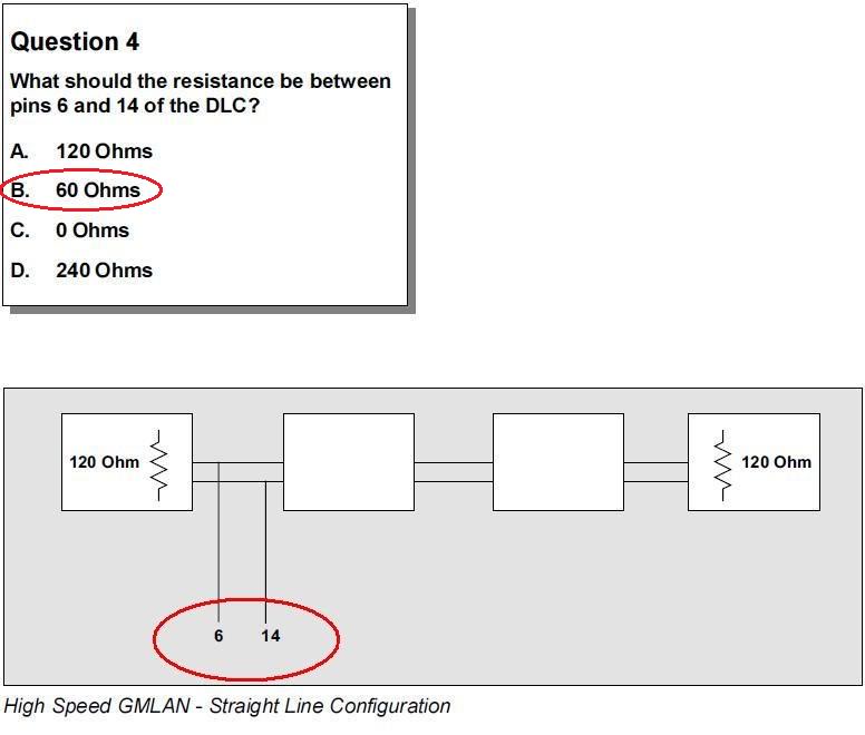
the 2 minutes is so no power is flowing on the circuit
Feb 26, 2012 | 03:15 PM
#46
If the GMLAN is open or shorted to either power or ground you will have no communication to any of the modules on that data system
If the BCM is unplugged you should have no communication with all of the High Spped LAN modules, so we can say the BCM is in place and the High Spped LAN circuits are in good shape. Also you would have 120 ohms on at the DLC between 6 & 14
This lead me to think that the BCM is not powering up or it is bad.
If the BCM is unplugged you should have no communication with all of the High Spped LAN modules, so we can say the BCM is in place and the High Spped LAN circuits are in good shape. Also you would have 120 ohms on at the DLC between 6 & 14
This lead me to think that the BCM is not powering up or it is bad.
Sorry, I am a little cornfused....
a bad BCM would would explain this issue but I want make sure everything is correct if possible before going down that route.
Last edited by 1FastBrick; Feb 26, 2012 at 03:20 PM.
Feb 26, 2012 | 03:34 PM
#47
You have 60 ohms on the DLC, so the BCM is in place and the High Spped LAN circuits are in good shape. Also you would have 120 ohms on at the DLC if the BCM was unplugged
Feb 26, 2012 | 03:39 PM
#48
If the BCM was missing or some how unplugged you wouls know this by having 120 ohms
You have 60 ohms on the DLC, so the BCM is in place and the High Spped LAN circuits are in good shape. Also you would have 120 ohms on at the DLC if the BCM was unplugged
You have 60 ohms on the DLC, so the BCM is in place and the High Spped LAN circuits are in good shape. Also you would have 120 ohms on at the DLC if the BCM was unplugged
 Ah ha!!! That makes perfect since.
So is there something else I should be Looking for???
Feb 26, 2012 | 03:47 PM
#50
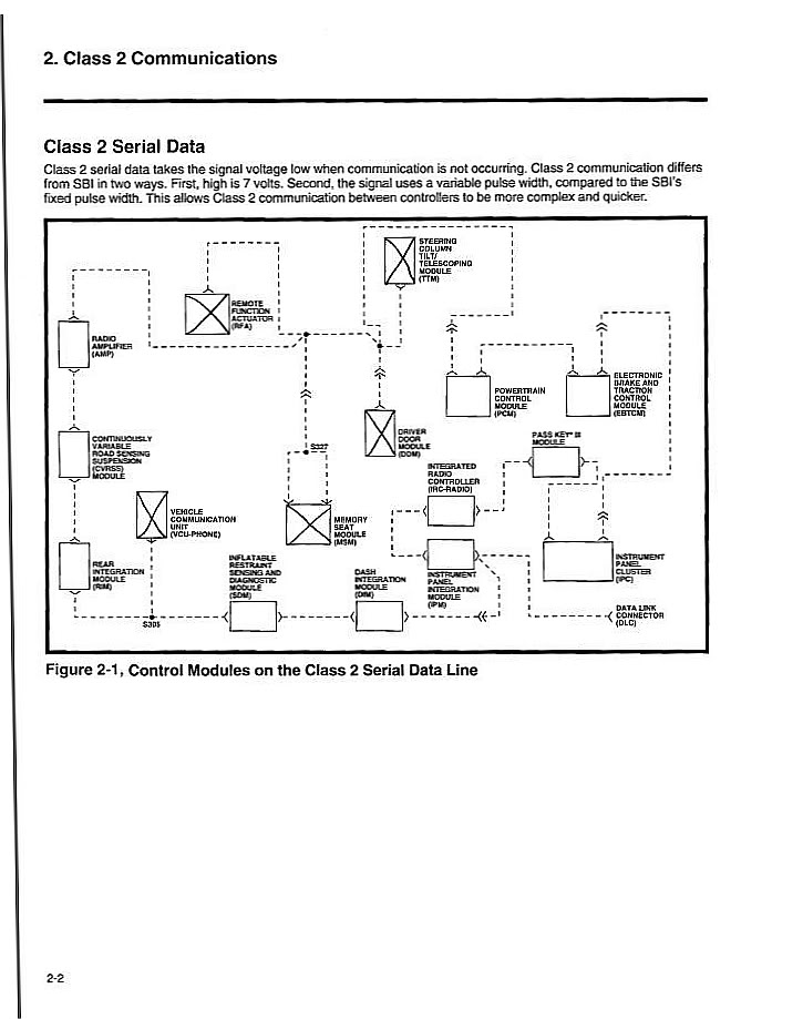
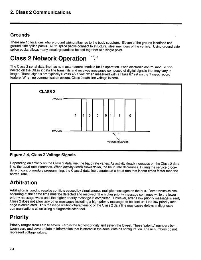
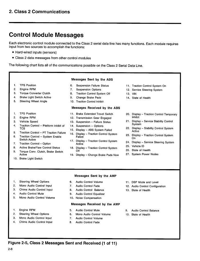
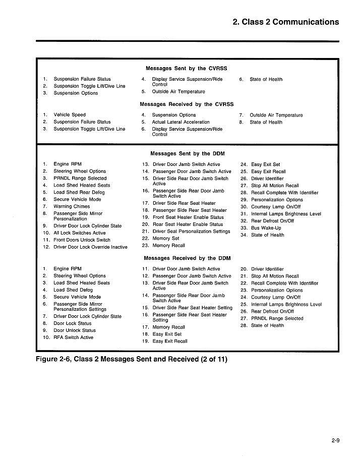
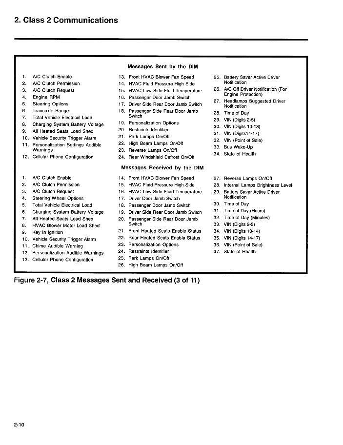
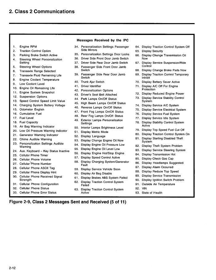
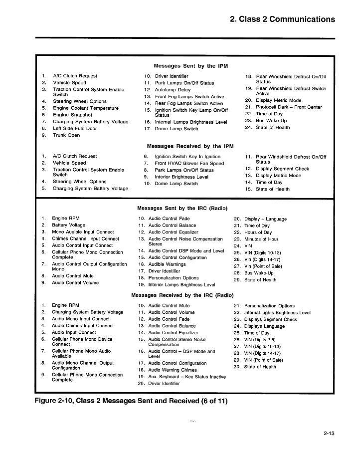
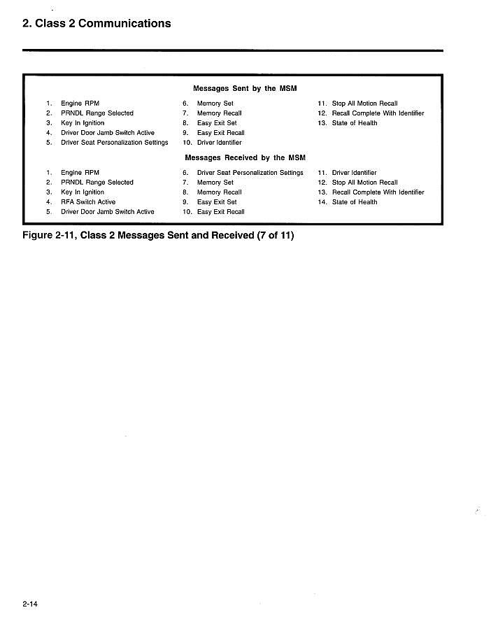
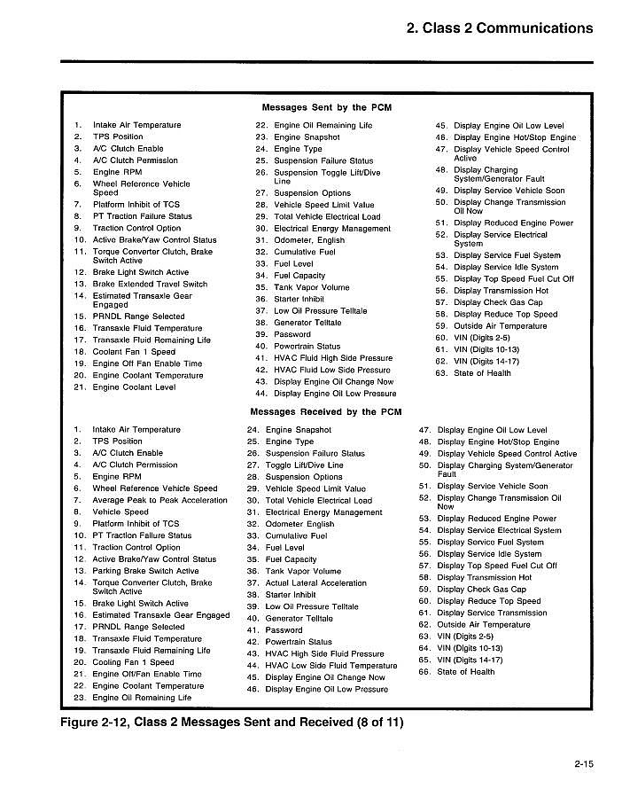
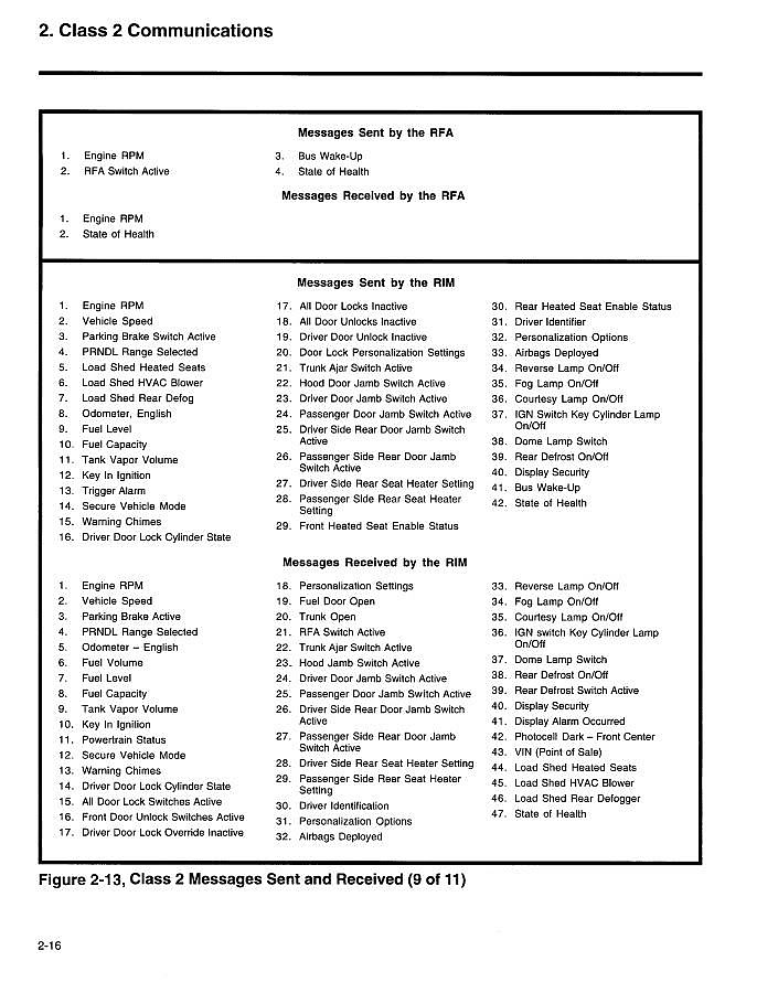
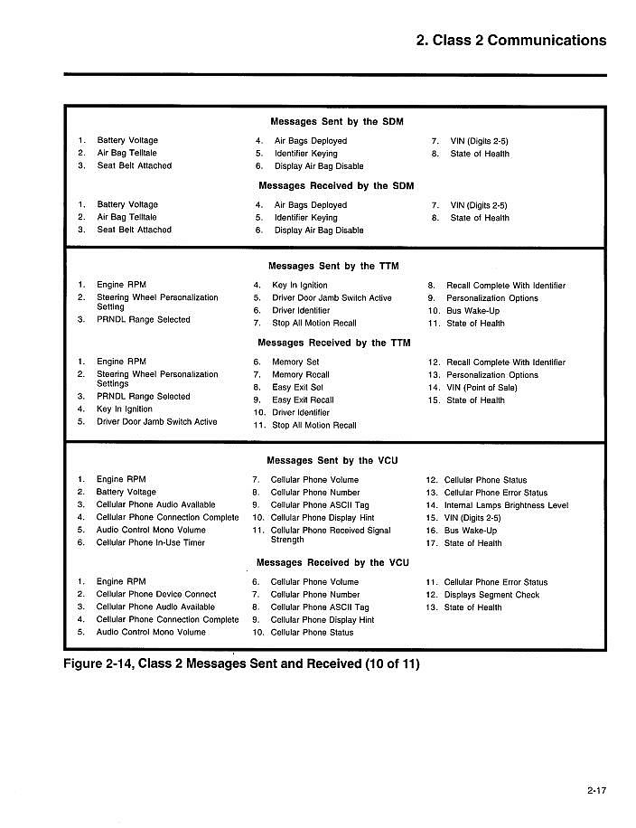
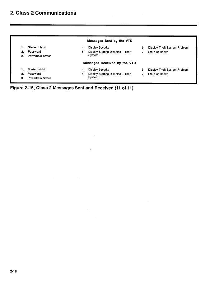
This is how the old Class II data circuit work.
If you look you will see modules repeating a message that it did not produce.
2-1
2-2
2-3
2-4
2-5
2-6
2-7
2-8
2-9
2-10
2-11

2-12
2-13
2-14
2-15
2-16
2-17
2-18
If you look you will see modules repeating a message that it did not produce.
2-1
2-2
2-3
2-4
2-5
2-6
2-7
2-8
2-9
2-10
2-11
2-12
2-13
2-14
2-15
2-16
2-17
2-18