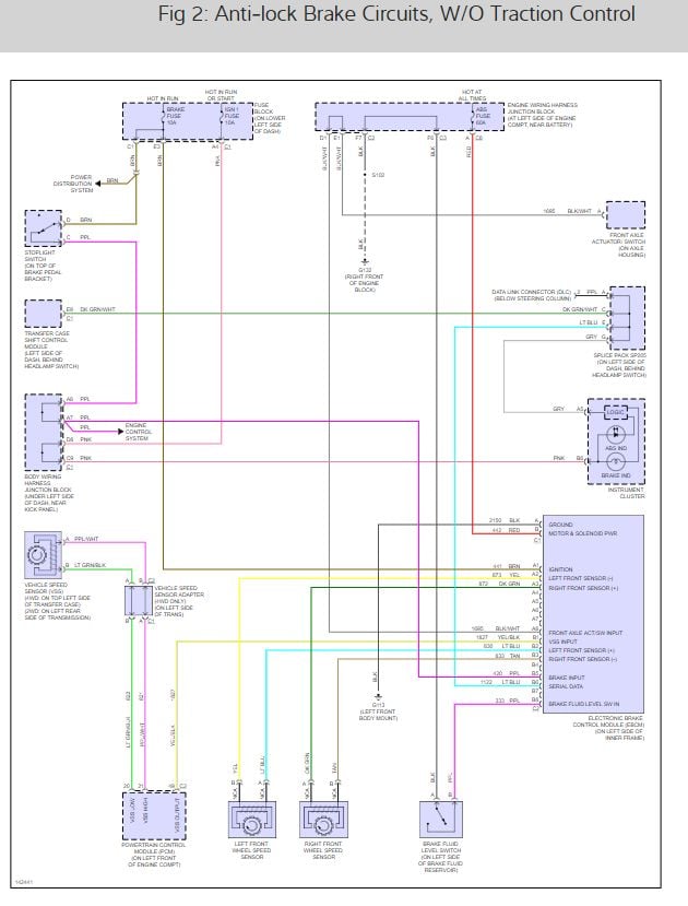
2003 silverado ABS speed sensor
#1
Does anybody know how the front wheel speed sensors work?
As in what type of signal is sent to the sensor? 12V+? Ground? 5 volt?
trying to figure out a simple poor mans traction control and don't want to fry this holley ecu.
As in what type of signal is sent to the sensor? 12V+? Ground? 5 volt?
trying to figure out a simple poor mans traction control and don't want to fry this holley ecu.
The following users liked this post:
strutaeng (09-19-2022)
#3
TECH Resident
I don't know for sure, but I assumed it was AC signal? It's just one wire, right?
I think when the ABS/Brake light finally came on on my 99 NBS I was looking to see if it was the wheel speed sensors. I remember checking with a DVOM. Somehow I determined the speed sensors were okay.
I think when the ABS/Brake light finally came on on my 99 NBS I was looking to see if it was the wheel speed sensors. I remember checking with a DVOM. Somehow I determined the speed sensors were okay.
The following 2 users liked this post by RB04Av:
GREENSIERRA (09-26-2022),
strutaeng (09-19-2022)
The following users liked this post:
strutaeng (09-19-2022)
The following users liked this post:
strutaeng (09-19-2022)
#7
No incoming "signals" at all. Just a pulse train leaving. Kinda like, there's no "signal" driving a microphone; just the electrical replica of the sound it picked up, leaving it. If you looked at the pulses being generated by the sensor they would look alot like the same shape as those little teeth. 

Trending Topics
#8
So the Low Reference in the wiring diagram is a Ground?
Ive done a lot of stuff with these trucks over the years but this is the first time ive ever dealt with this type of sensor and such.
Trying to learn
Ive done a lot of stuff with these trucks over the years but this is the first time ive ever dealt with this type of sensor and such.
Trying to learn

The following users liked this post:
strutaeng (09-19-2022)
#9
So the Low Reference in the wiring diagram is a Ground
In professional applications (broadcast, recording studios, live sound, etc.) we always connect things like microphones and other low-level transducers as "balanced". 2 wires go to the low-level transducer (mic, phono cartridge, whatever), and the amplifier they're hooked to is set up to only respond to the difference between the signal on the 2 wires. Signals that would affect both wires equally, referred to as "common mode", are rejected and ignored. Kinda the same idea here. Misc noise such as from nearby other wires, whatever is on chassis ground, nearby AM radio transmitters, and so on, doesn't corrupt the signal. Cheeeeeeep consumer-grade audio gear uses RCA plugs and the like, where one conductor is "ground". IOW any difference in "ground" potential between the 2 ends of the cable appears in the output, corrupting the signal. (hum, weird scratchy noises, etc.) To be avoided in critical life-safety (brakes) applications.
The following users liked this post:
strutaeng (09-19-2022)
The following users liked this post:
strutaeng (09-25-2022)
Thread
Thread Starter
Forum
Replies
Last Post
03 BLACKOUTSSS
GMT 800 & Older GM General Discussion
18
09-21-2009 12:31 PM


