

Camping Truck Build, '01 Suburban 2500
 Jul 28, 2013 | 09:22 AM
#1
Thread Starter
TECH Fanatic

Joined: Jun 2011
Posts: 1,292
Likes: 5
From: Houston
This thread is meant to consolidate and present all the mods done to my 2001 Suburban 2500 4x4. Hopefully this thread allows me to share my findings and also get feedback from the community here.
I bought the truck in April 2012 for $8800 with 116k miles in excellent condition.
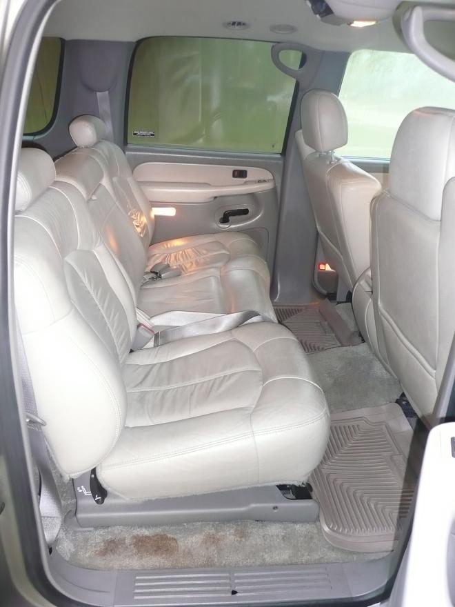
The goal for this truck is a reliable, street-drivable, powerful, capable off-road truck. I want to preserve all things that make this truck drivable cross-country or down a dirt trail. Our particular brand of camping is primitive, total wilderness with enough supplies to last 3-5 days. The 4x4 suburban is great for that.
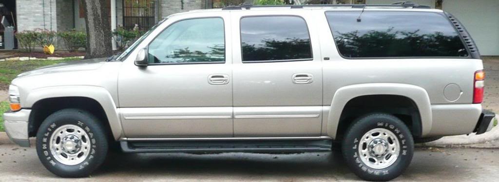
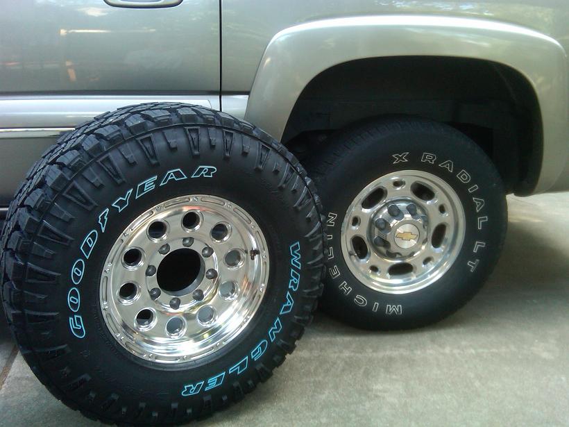
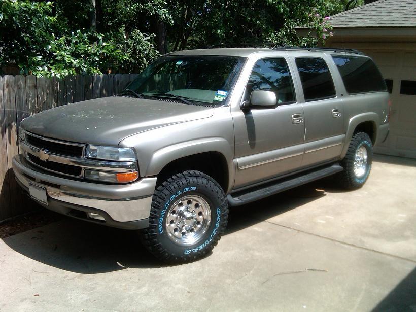
The first mod was the tires and wheels.
clearance is a little tight. I removed some of the plastic liner, but it still rubs on hard turns over bumps.
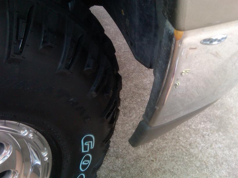
Looks better.
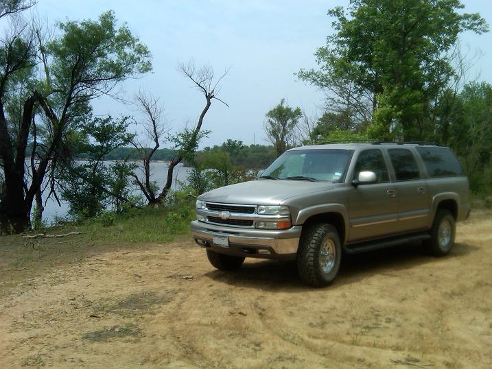
Here is the truck on the shores of Blue Mountain Lake, Arkansas.
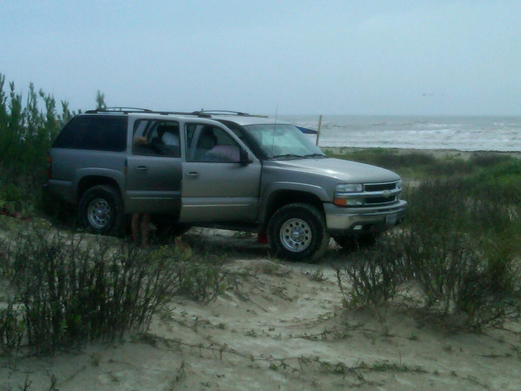
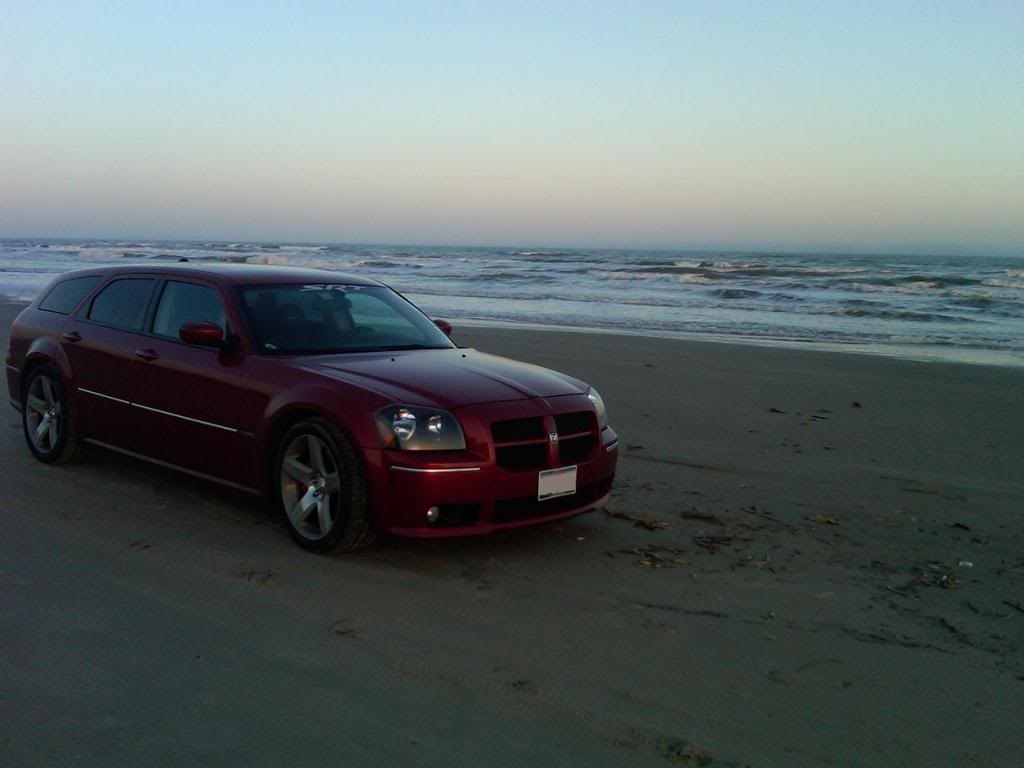
Camping near Surfside Beach, TX, May 2013.
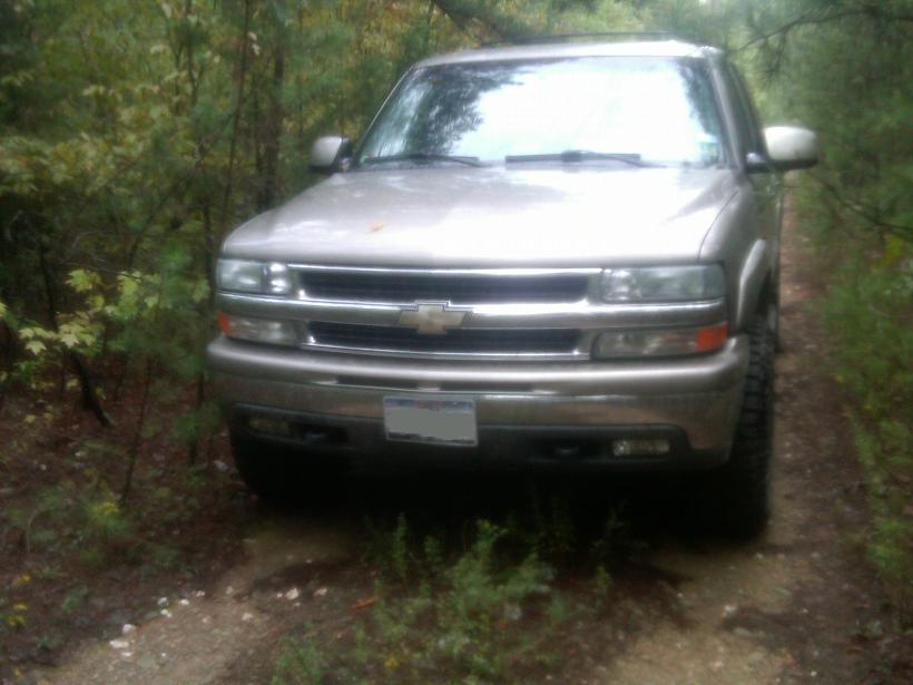
Lake Ouachita, AR, September 2012
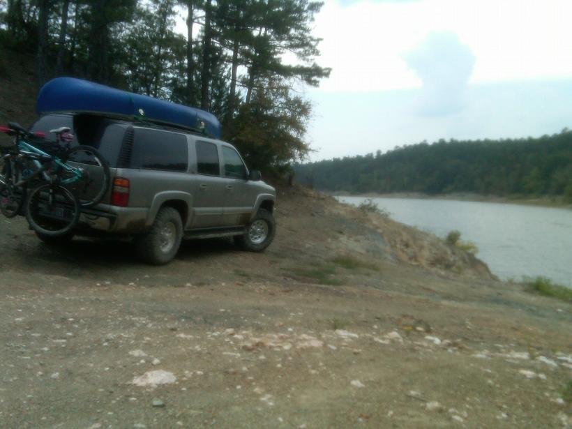

The tires are Goodyear Wrangler Duratrac 285/75/16 and they do great off road. I've had them in all kinds of mud, sand, rocks, etc. and they have never let me down. They are also very quiet at highway speeds 80+ mph.
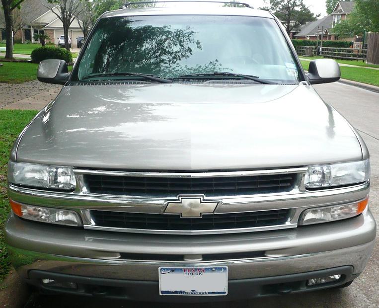
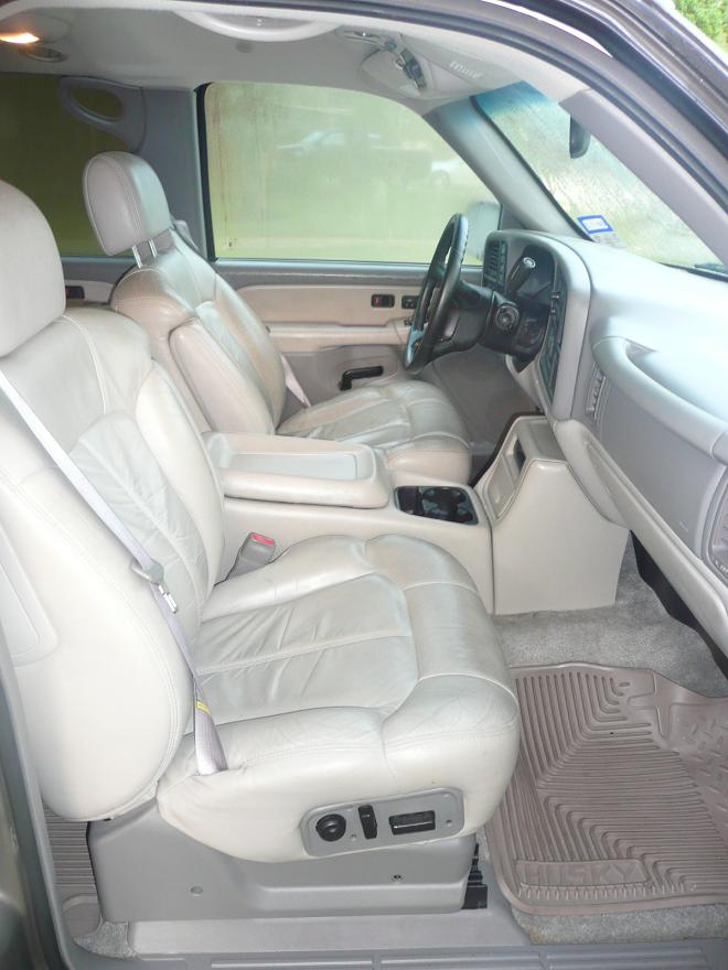
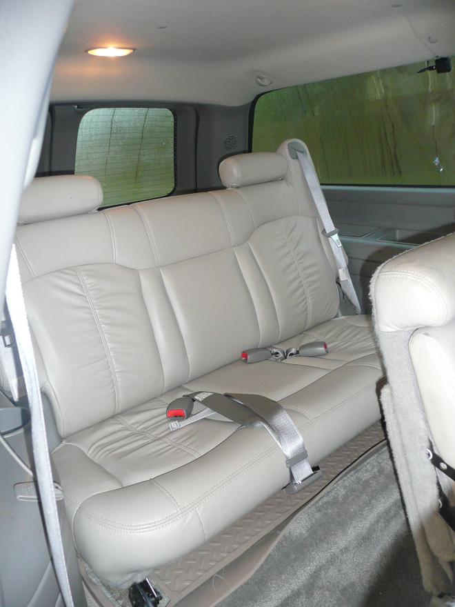
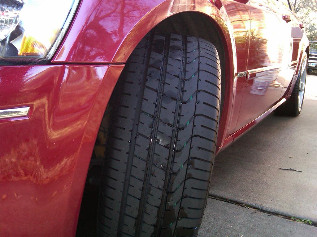
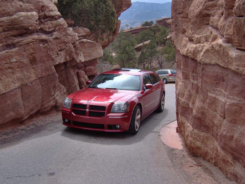
Some pictures of the daily driver.
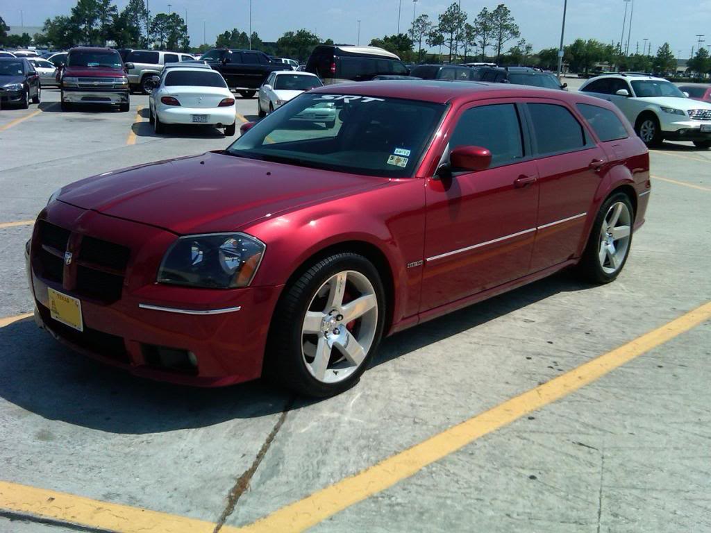
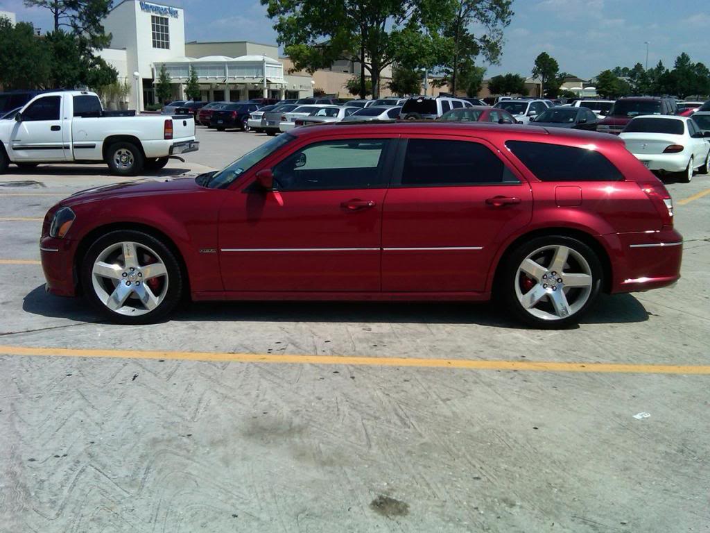
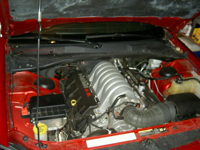
The 6.1 hemi is an amazing engine. Simple, reliable, easy to work on, clean, no EGR, no VVT, very aesthetic, etc...
I bought the truck in April 2012 for $8800 with 116k miles in excellent condition.


The goal for this truck is a reliable, street-drivable, powerful, capable off-road truck. I want to preserve all things that make this truck drivable cross-country or down a dirt trail. Our particular brand of camping is primitive, total wilderness with enough supplies to last 3-5 days. The 4x4 suburban is great for that.
The first mod was the tires and wheels.

clearance is a little tight. I removed some of the plastic liner, but it still rubs on hard turns over bumps.

Looks better.

Here is the truck on the shores of Blue Mountain Lake, Arkansas.

Camping near Surfside Beach, TX, May 2013.

Lake Ouachita, AR, September 2012


The tires are Goodyear Wrangler Duratrac 285/75/16 and they do great off road. I've had them in all kinds of mud, sand, rocks, etc. and they have never let me down. They are also very quiet at highway speeds 80+ mph.
Some pictures of the daily driver.


The 6.1 hemi is an amazing engine. Simple, reliable, easy to work on, clean, no EGR, no VVT, very aesthetic, etc...

Last edited by RezinTexas; Jul 29, 2013 at 06:35 PM.
 Jul 28, 2013 | 09:33 AM
#3
Thread Starter
TECH Fanatic
Joined: Jun 2011
Posts: 1,292
Likes: 5
From: Houston
The next upgrade was the engine swap. Why put such a high-performance engine in a Suburban? Good question, the answer is twofold:
1. I wanted to learn how to build an engine. It was a fun project and I'm glad I did it.
2. I do not have room for a project car, so I decided to put the engine in my wife's suburban. She is an avid cyclist so she almost never drives it anyway...
I'm already thinking about what to put the engine in next. 2-door Jeep Wrangler maybe? Then I can add a duramax to the suburban, who knows.
At the time I bought this truck, I already had an assembled 383 iron short block, so I decided to keep what I had and sell the 6.0 that this suburban came with from the factory.
I realize now that for the amount of $$ spent on this build I could have done a 408 or maybe even more, however the scope and budget of this build has evolved significantly since I started the project in 2011... It was the power bug, I was totally helpless
Here are the specs of the original engine build.
2004 LM7 5.3 Iron Block
Machine work at HKE, Houston TX:
Bore & Hone to 3.903"
Line hone with ARP studs
Machine the deck to -0.010" target deck height
Rotating Assembly:
K1 Technologies 4" stroker crank
Eagle H-beam rods
Wiseco -3cc pistons
Wiseco GFX piston rings
Balanced by TSP
Clevite H & HX bearings
ARP main studs
Heads & Valvetrain:
AFR 210 heads, milled to 63cc
Patrick G spec'd cam: 224/228 .566”/.571” 115 LSA +1 adv, XE lobes
New GM "LS7" lifters
Comp Chromeoly pushrods 7.325" (0.045" preload)
OEM rocker arms with Comp trunnion upgrade
OEM LS2 timing set
Cometic head gaskets
ARP crank bolt
ARP camshaft bolts
ARP head studs
Engine Assembly:
All new gaskets
Melling HP oil pump
FAST 36lb injectors
4" intake tube, K&N air filter
MSD spark plug wires
Exhaust:
TSP 1-3/4" long tube SS headers
Dual 3" straight pipes
Magnaflow 22" 2-in 2-out muffler
Dual 4" tips
Intake Assembly:
OEM fuel rails
Tony Mamo Ported FAST LSXRT 102mm
FAST 92mm throttle body
__________________________________________________ __________________
COMPRESSION RATIOS AND MATH:
Here is a link to the written calculations: http://www.scribd.com/doc/145057435/...RAFT-01-Jun-13
Screen shot of the spreadsheet and results for this 383 engine. The deck heights were incorrectly machined at HKE, so I had to run different thickness head gaskets to make up the difference.
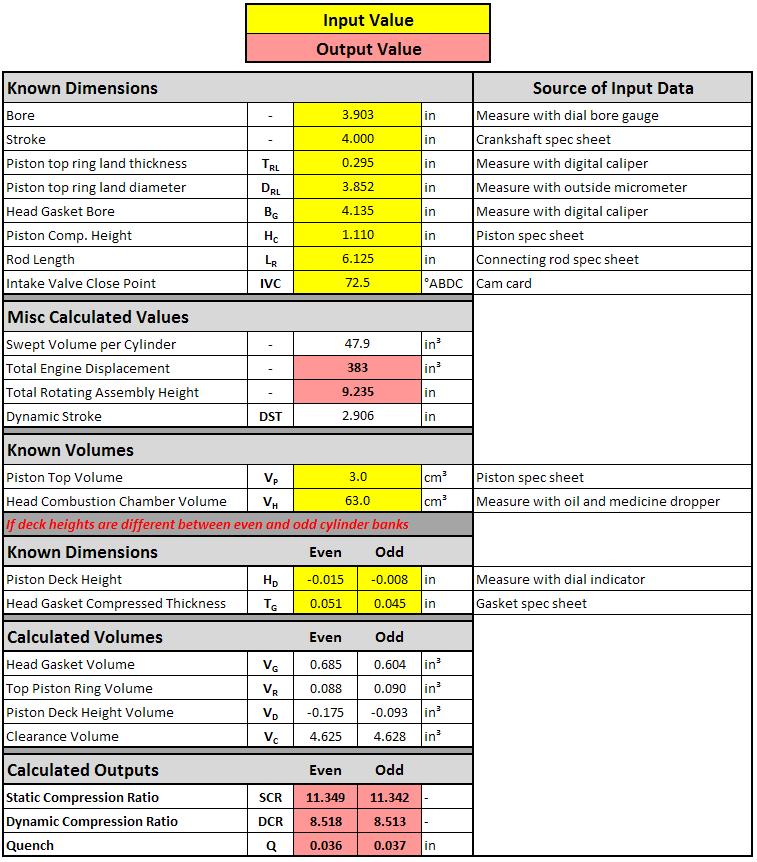
Illustrations of parameters used for calculating compression ratios:
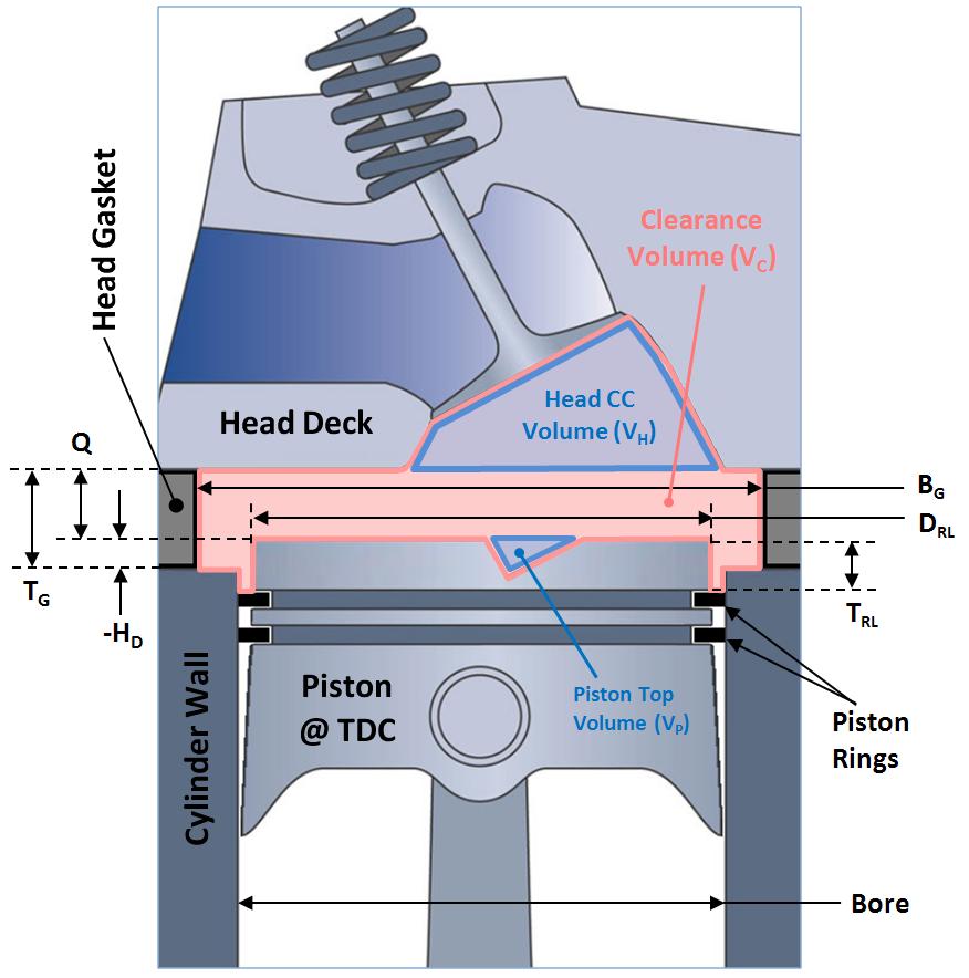
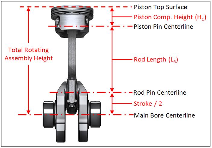
__________________________________________________ __________________
Now onto the build pics!
Unloading the engine after purchase at LKQ:
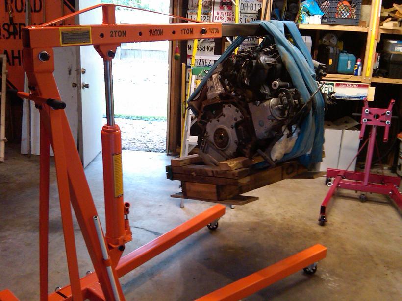
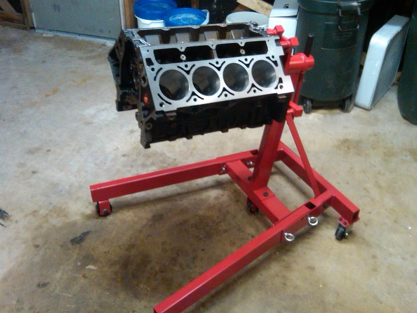
Load leveler to put engine on stand:
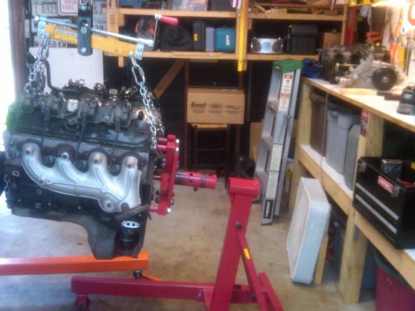
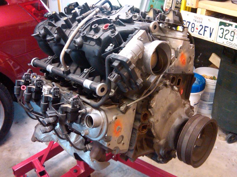
Junkyard 5.3 in all its glory!
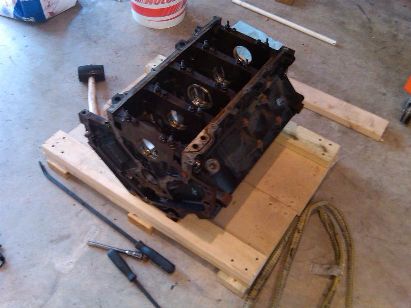
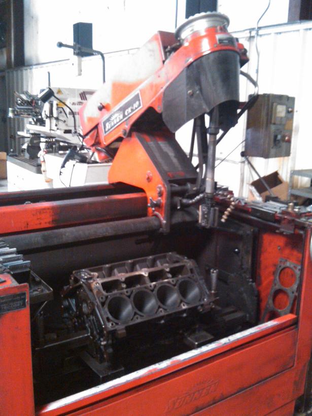
Block torn down ready for machining:
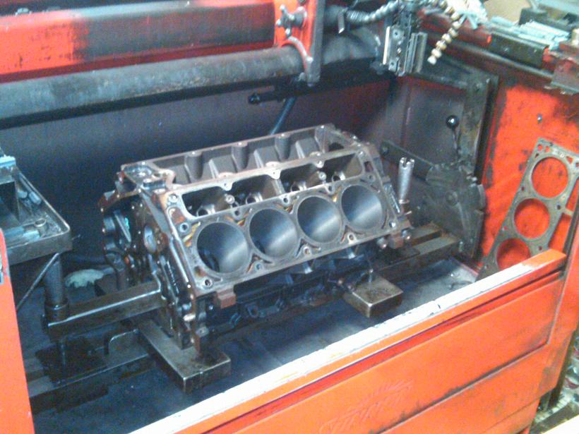
Machining at HKE:
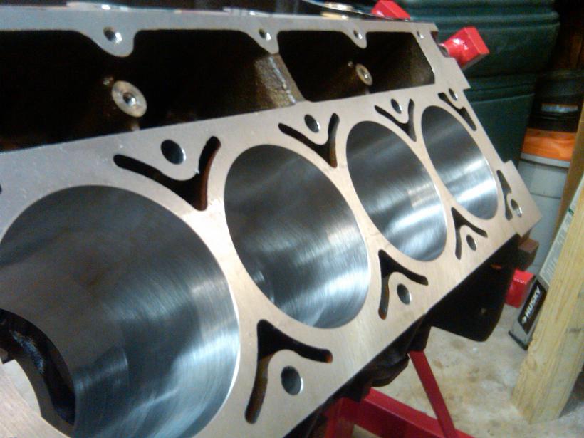
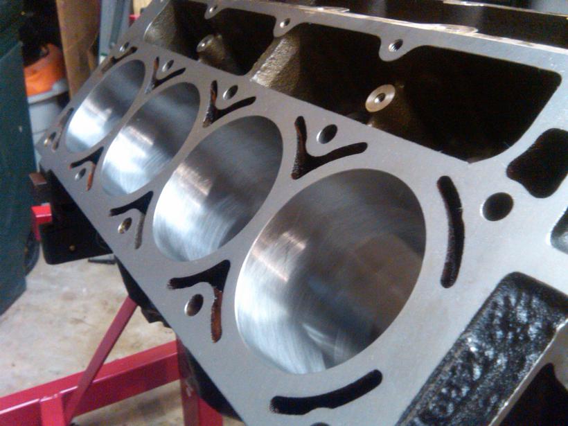
Home after machining at HKE:
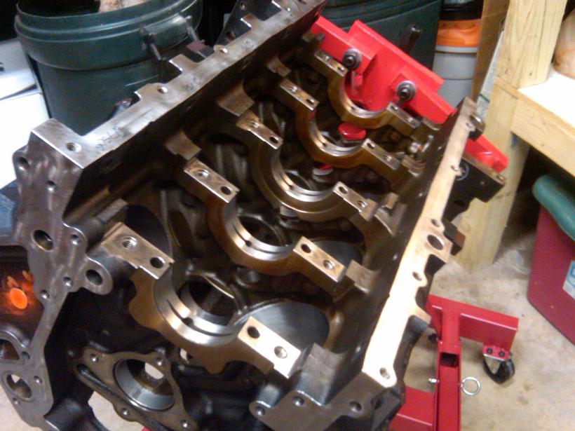
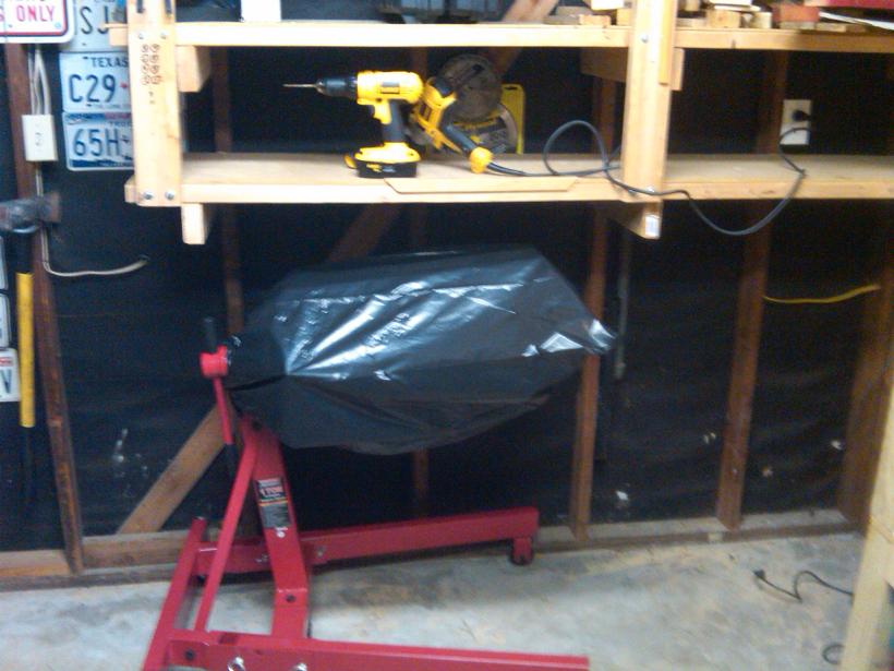
Engine block long term storage. I adjusted the height of my shelf to fit the block with intake manifold.
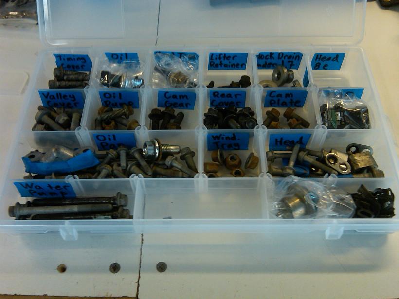
Engine fastener long term storage:
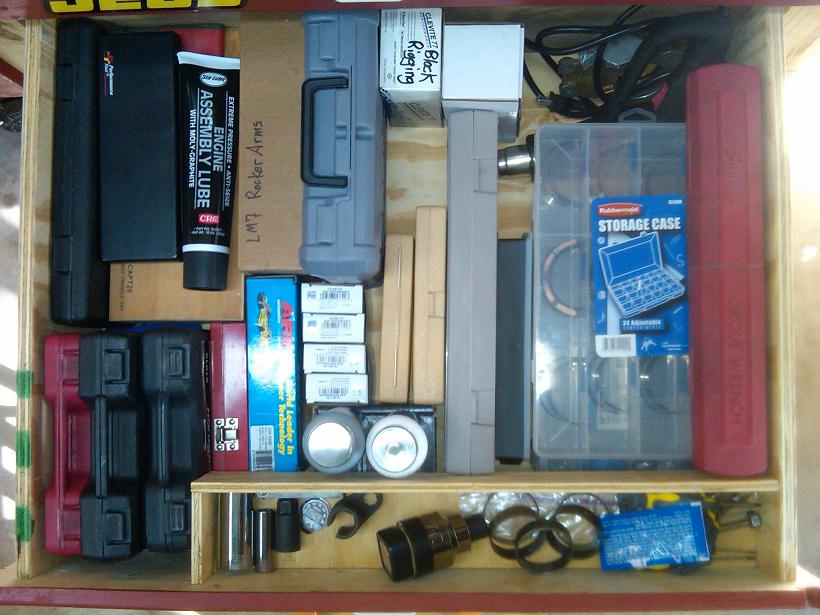
Misc engine tools organized in drawer:
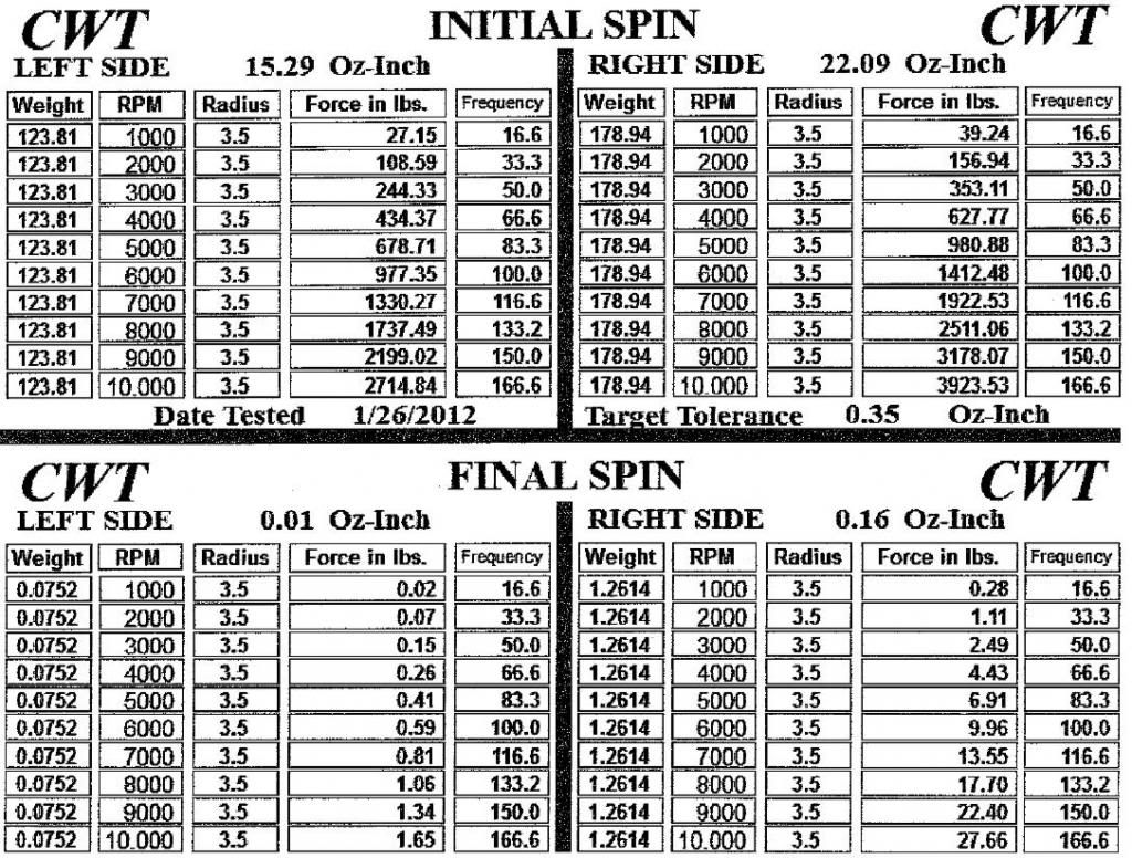
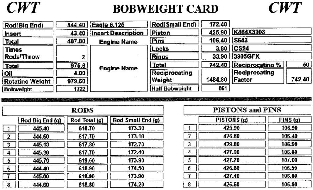
After a few months the balanced rotating assembly arrived from TSP.
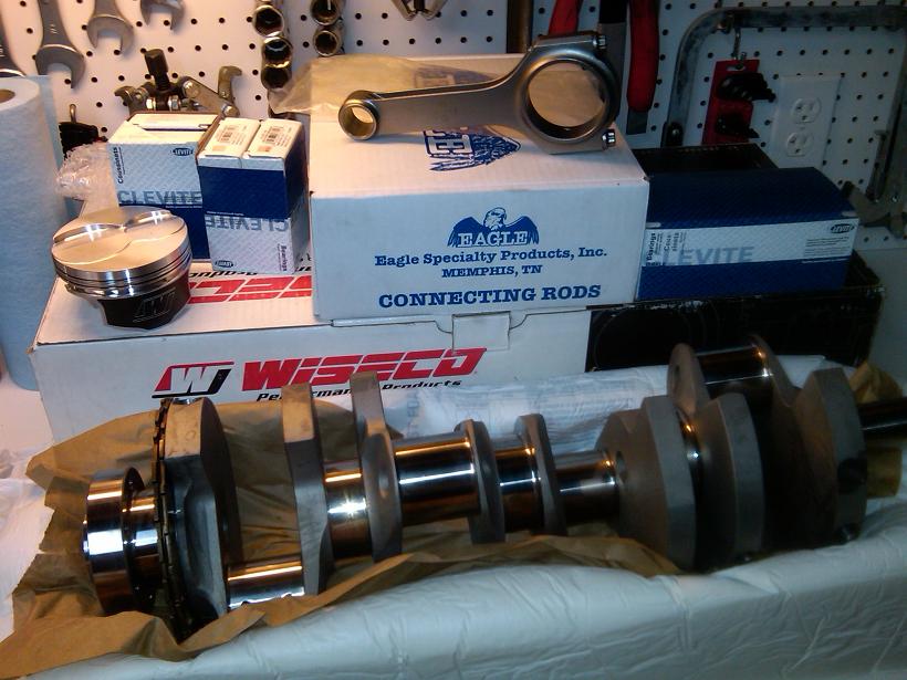
Here is the balance sheet data:
1. I wanted to learn how to build an engine. It was a fun project and I'm glad I did it.
2. I do not have room for a project car, so I decided to put the engine in my wife's suburban. She is an avid cyclist so she almost never drives it anyway...
I'm already thinking about what to put the engine in next. 2-door Jeep Wrangler maybe? Then I can add a duramax to the suburban, who knows.
At the time I bought this truck, I already had an assembled 383 iron short block, so I decided to keep what I had and sell the 6.0 that this suburban came with from the factory.
I realize now that for the amount of $$ spent on this build I could have done a 408 or maybe even more, however the scope and budget of this build has evolved significantly since I started the project in 2011... It was the power bug, I was totally helpless
Here are the specs of the original engine build.
2004 LM7 5.3 Iron Block
Machine work at HKE, Houston TX:
Bore & Hone to 3.903"
Line hone with ARP studs
Machine the deck to -0.010" target deck height
Rotating Assembly:
K1 Technologies 4" stroker crank
Eagle H-beam rods
Wiseco -3cc pistons
Wiseco GFX piston rings
Balanced by TSP
Clevite H & HX bearings
ARP main studs
Heads & Valvetrain:
AFR 210 heads, milled to 63cc
Patrick G spec'd cam: 224/228 .566”/.571” 115 LSA +1 adv, XE lobes
New GM "LS7" lifters
Comp Chromeoly pushrods 7.325" (0.045" preload)
OEM rocker arms with Comp trunnion upgrade
OEM LS2 timing set
Cometic head gaskets
ARP crank bolt
ARP camshaft bolts
ARP head studs
Engine Assembly:
All new gaskets
Melling HP oil pump
FAST 36lb injectors
4" intake tube, K&N air filter
MSD spark plug wires
Exhaust:
TSP 1-3/4" long tube SS headers
Dual 3" straight pipes
Magnaflow 22" 2-in 2-out muffler
Dual 4" tips
Intake Assembly:
OEM fuel rails
Tony Mamo Ported FAST LSXRT 102mm
FAST 92mm throttle body
__________________________________________________ __________________
COMPRESSION RATIOS AND MATH:
Here is a link to the written calculations: http://www.scribd.com/doc/145057435/...RAFT-01-Jun-13
Screen shot of the spreadsheet and results for this 383 engine. The deck heights were incorrectly machined at HKE, so I had to run different thickness head gaskets to make up the difference.

Illustrations of parameters used for calculating compression ratios:


__________________________________________________ __________________
Now onto the build pics!
Unloading the engine after purchase at LKQ:

Load leveler to put engine on stand:

Junkyard 5.3 in all its glory!

Block torn down ready for machining:

Machining at HKE:


Home after machining at HKE:


Engine block long term storage. I adjusted the height of my shelf to fit the block with intake manifold.

Engine fastener long term storage:

Misc engine tools organized in drawer:

After a few months the balanced rotating assembly arrived from TSP.

Here is the balance sheet data:


Last edited by RezinTexas; Aug 24, 2013 at 03:57 PM.
Jul 28, 2013 | 09:33 AM
#4
Thread Starter
TECH Fanatic
Joined: Jun 2011
Posts: 1,292
Likes: 5
From: Houston
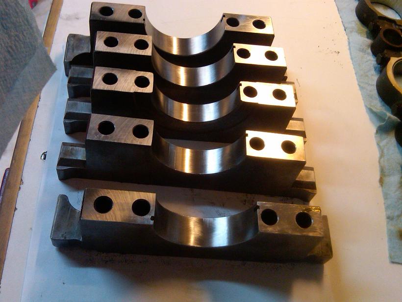
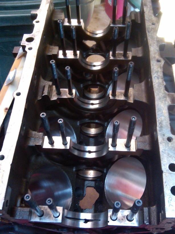
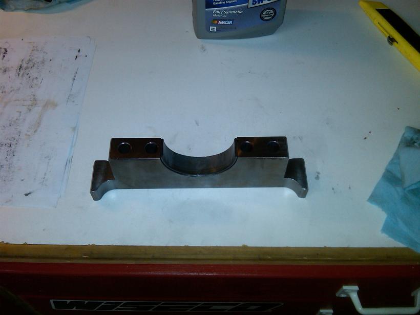
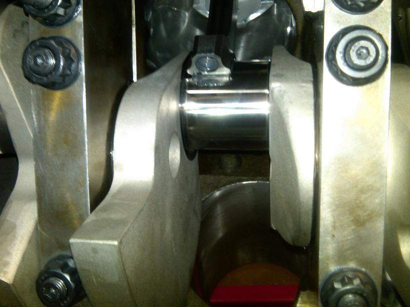
Now the assembly starts. Main caps cleaned and dusted:
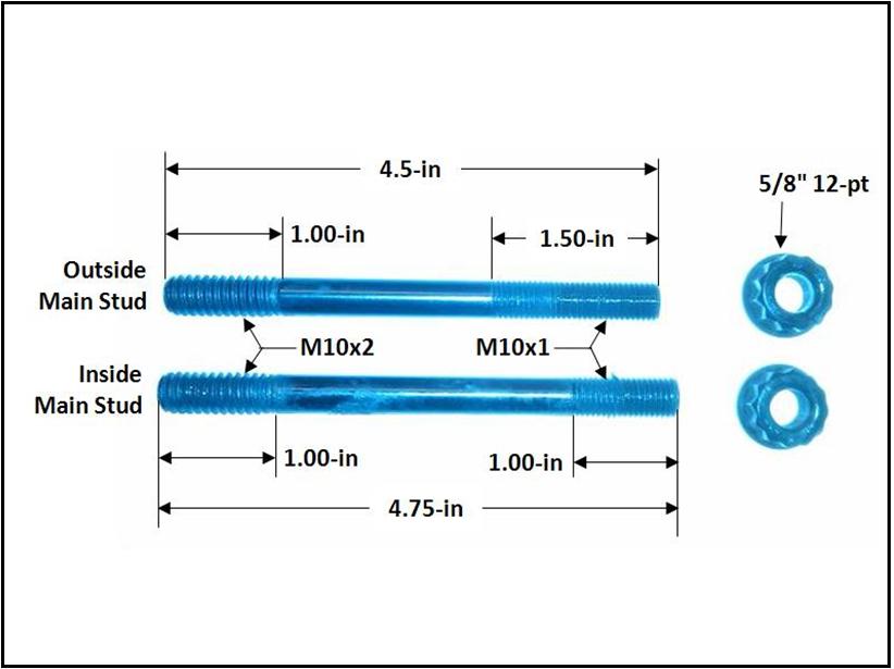
ARP Main Studs P/N: 234-5608:
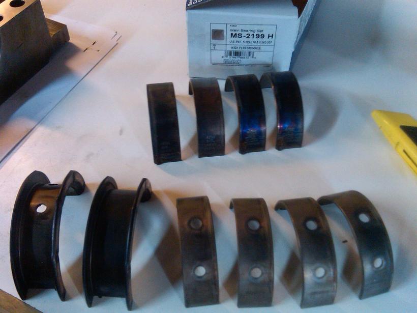
Main bearings, Clevite P/N: MS-2199H:
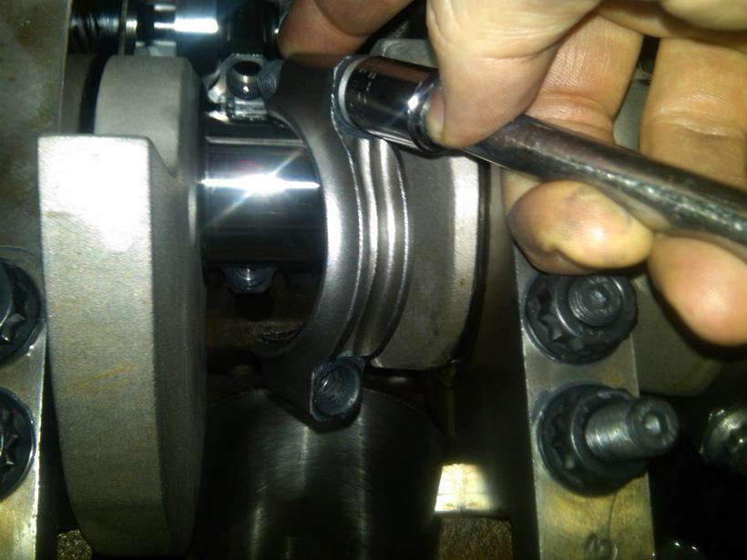
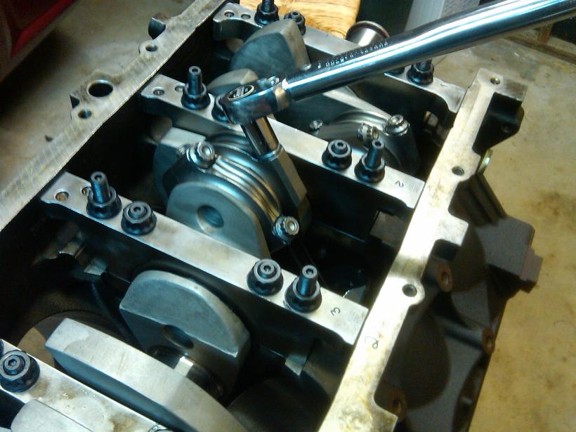
Torquing the main studs in 3 steps each, inward to outward. Started with 20 lb-ft each, ended with 62 lb-ft on the inner studs and 52 lb-ft on the outer studs.
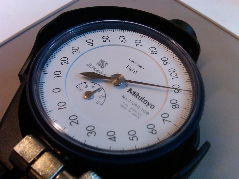
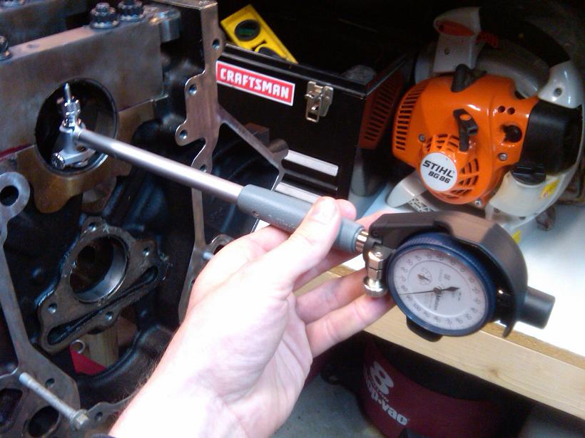
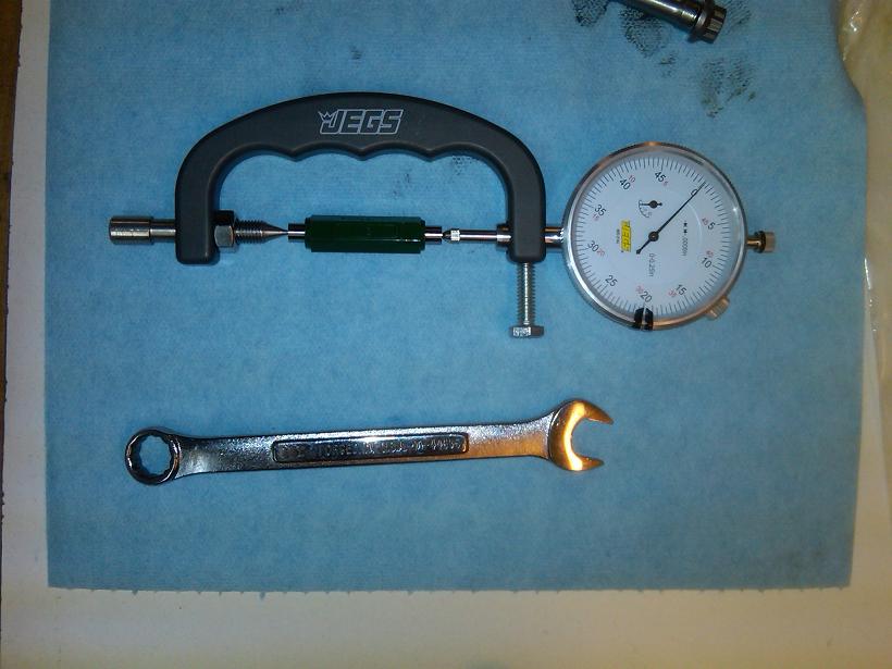
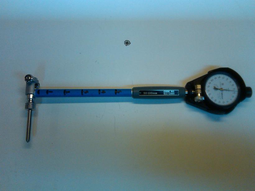
Now it's time to measure the main clearances. Dial bore gauge with 0.001mm resolution. That is 0.0000394" !!!
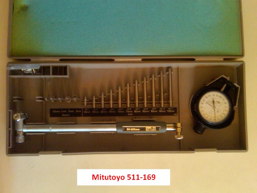
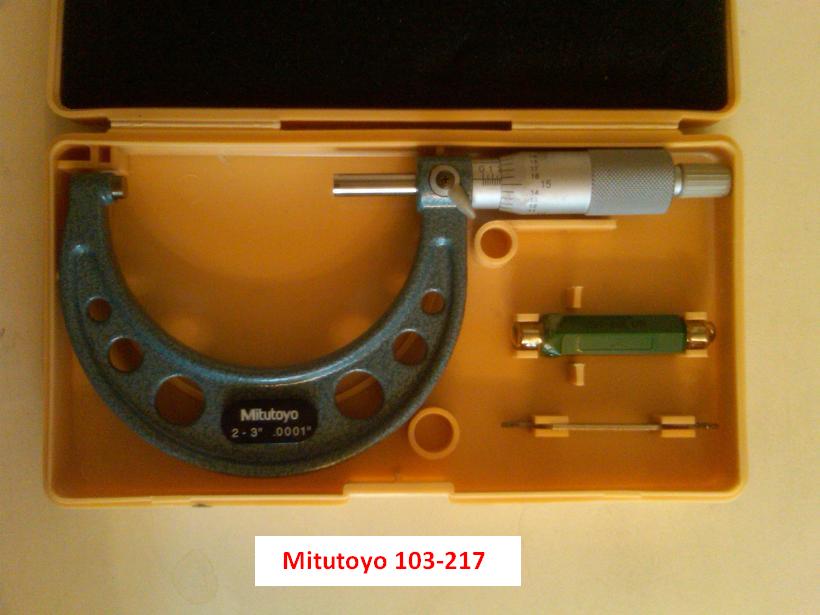
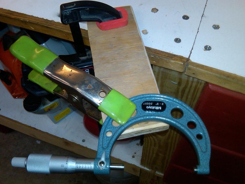
2-3" outside micrometer:
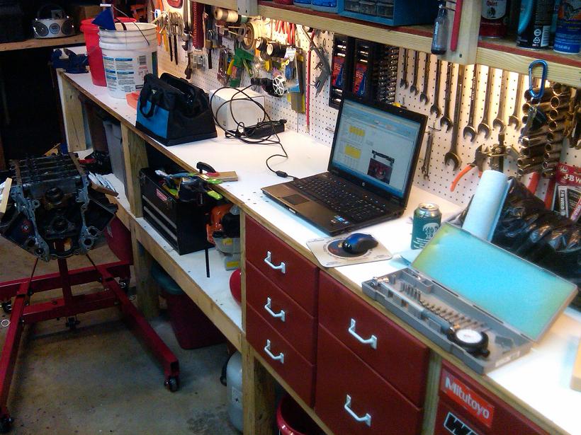
Clean workspace:
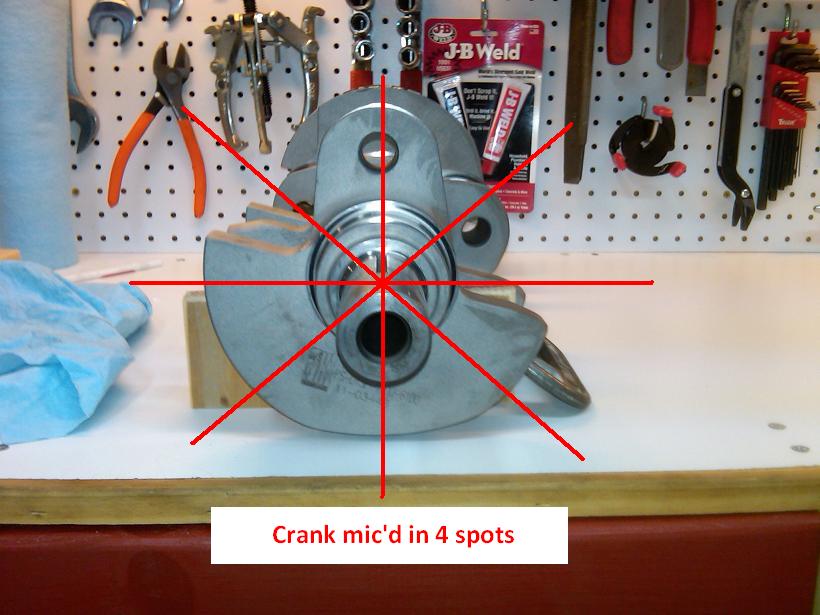
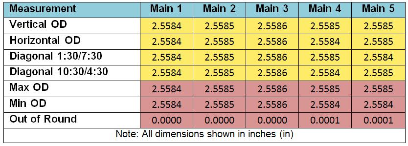
I measured the crank main journals in 4 places each with the micrometer:
Main journal dimensions on this K1 4" crank:
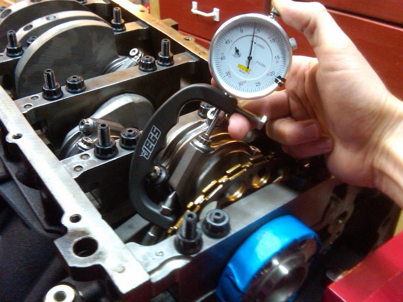
To use the dial bore gauge on the main bearing bores, setup the micrometer as shown and set it to the minimum value from each crank journal dimension.
Using 2 hands, set the dial bore gauge with the correct mandrel and spacers and calibrate it to the micrometer as shown. Adjust the dial bezel so it reads 0 when measuring the span of the micrometer evenly and squarely. This can be a little tedious, but patience and steady hands will bring success.
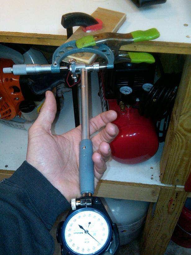
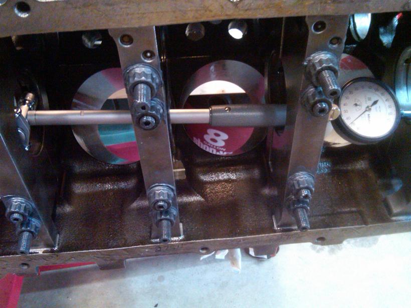
Once the dial bore gauge is calibrated, measure the bores as shown. I took one reading on each side of the oil galley.

ARP Main Studs P/N: 234-5608:


Main bearings, Clevite P/N: MS-2199H:


Torquing the main studs in 3 steps each, inward to outward. Started with 20 lb-ft each, ended with 62 lb-ft on the inner studs and 52 lb-ft on the outer studs.

Now it's time to measure the main clearances. Dial bore gauge with 0.001mm resolution. That is 0.0000394" !!!


2-3" outside micrometer:

Clean workspace:

I measured the crank main journals in 4 places each with the micrometer:

Main journal dimensions on this K1 4" crank:

To use the dial bore gauge on the main bearing bores, setup the micrometer as shown and set it to the minimum value from each crank journal dimension.

Using 2 hands, set the dial bore gauge with the correct mandrel and spacers and calibrate it to the micrometer as shown. Adjust the dial bezel so it reads 0 when measuring the span of the micrometer evenly and squarely. This can be a little tedious, but patience and steady hands will bring success.

Once the dial bore gauge is calibrated, measure the bores as shown. I took one reading on each side of the oil galley.


Last edited by RezinTexas; Aug 24, 2013 at 02:03 PM.
Jul 28, 2013 | 09:35 AM
#5
Thread Starter
TECH Fanatic
Joined: Jun 2011
Posts: 1,292
Likes: 5
From: Houston
Calculated clearances:
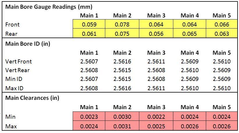
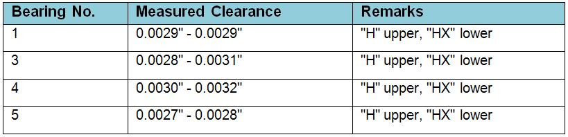
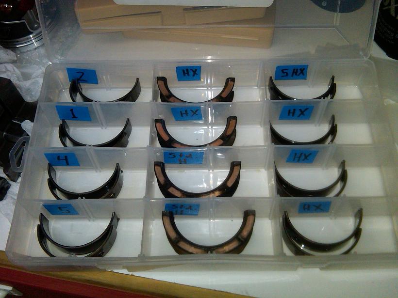
My references for ideal iron block main clearances range from 0.0024" - 0.0031", all from reputable sources. I determined that all except for #2 were too tight for my liking so I substituted those lower half shells with HX bearings. The re-measured clearances are shown below.
I kept the left-over bearing shells in storage for use later.
Then it was time to measure the connecting rod bearing clearances. The methodology is pretty much the same. While the crank was still out, I measured the rod journals with the 2-3" micrometer. Here are the results.
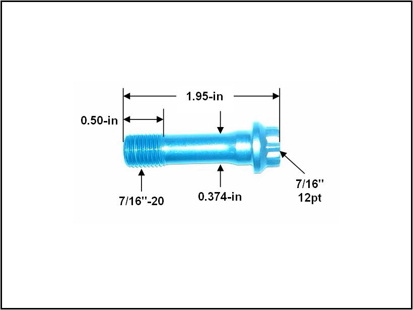
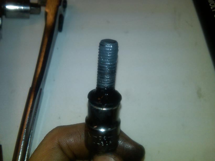
Here are the dimensions of the selected rod bolt. ARP 8740 material.
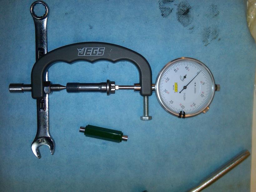
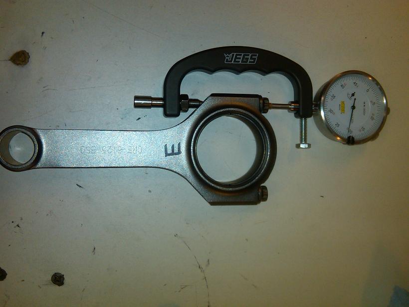
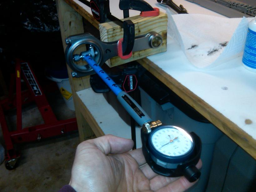
In order to measure the free-standing length of each rod bolt, I calibrated the rod bolt stretch gauge to read ZERO when the 2" standard was installed straight.
Then the free length and installed length of each rod bolt was measured. The rods were named A through H. I didn't use numbers because at this point I was aiming to match the rods with the best fitting locations on the crankshaft. Unlike the mains, the rods are not tied to any one spot on the crankshaft.
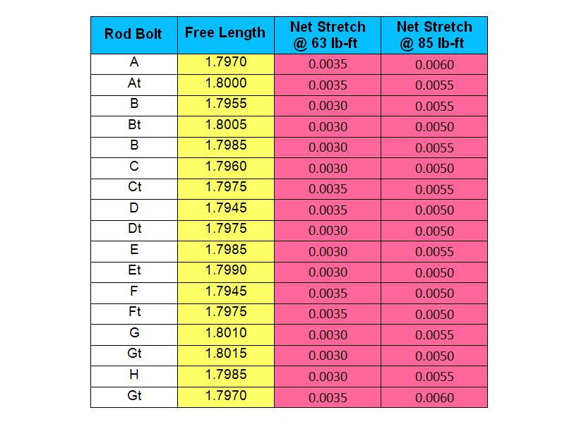
Here are the measurements of each rod bolt. The "t" denotes the bolt that was adjacent the bearing tangs. As you can see, the initial torquing of 63 lb-ft (per ARP instructions) resulted in less stretch than the ARP specification of 0.0059" - 0.0063". Because of this discrepancy, it was decided to re-torque each rod bolt until a higher stretch was achieved. After the 85 lb-ft was applied, the bolts were checked again for free length to ensure there was no permanent stretch. There was none.
A basic stress analysis was done for the rod bolts as explained here:
http://www.scribd.com/doc/160936551/...d-Bolt-Preload
After the correct torque was selected, the ID of each rod bearing was measured with the dial bore gauge. Just FYI, the clearances did not change between the 63 lb-ft and 85 lb-ft input torque on the rod caps.
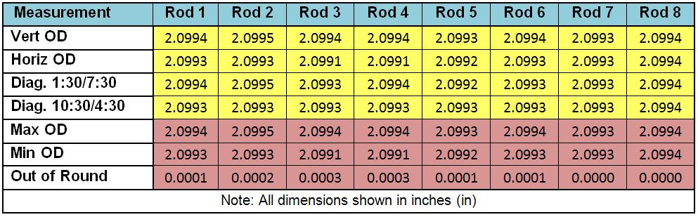
Here are the measured ID's of each rod big end (with bearing):
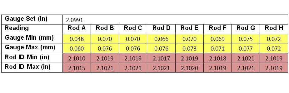
Recommended rod bearing clearances range from 0.0016" - 0.0026" taken from reputable sources. To assign each rod to the best fitting location on the crank shaft, all possibilities were calculated and charted as shown below. Yellow is low value, Green is medium, Red is high. The black boxes indicate the chosen parings.
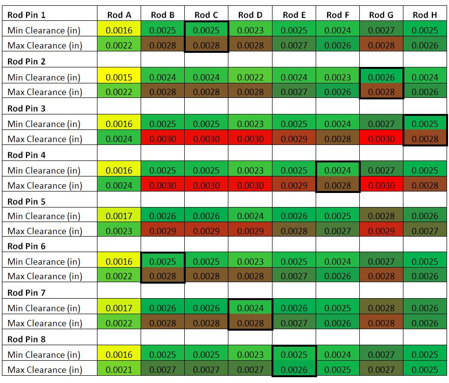
As can be seen above, the values for "Rod A" were too low for my liking. A single HX bearing half shell was swapped over and resulted in a clearance range of 0.0020" - 0.0030". This was chosen for the build.
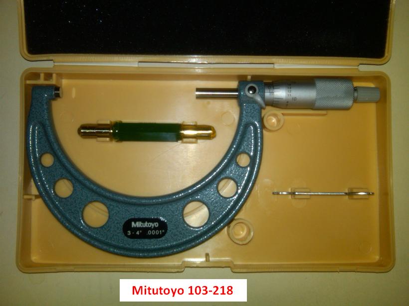
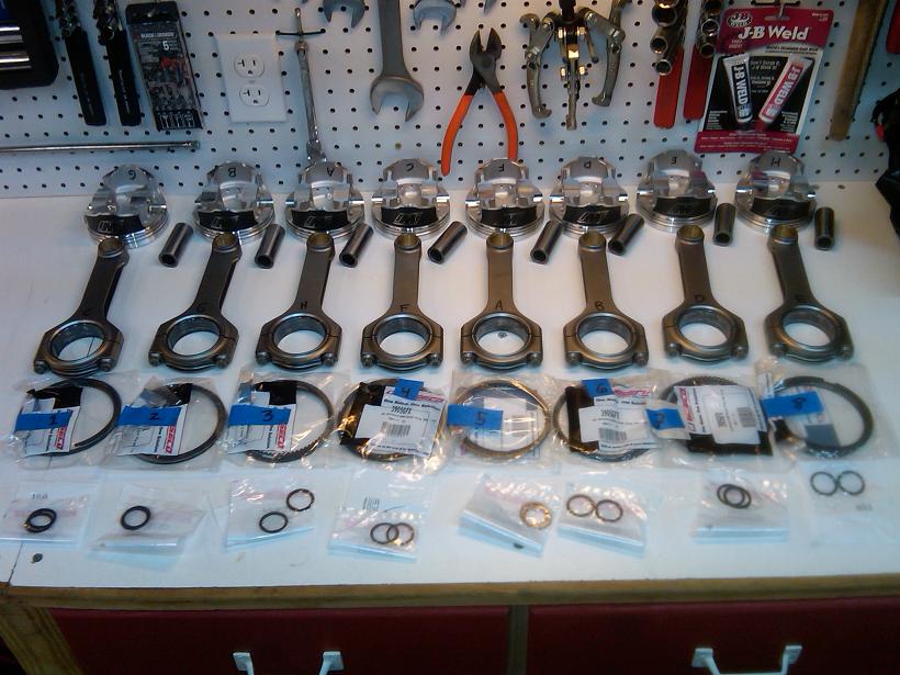
Next it was time to assign each piston to the best fitting cylinder, just like the rods. The pistons were each measured with a 3-4" micrometer as shown:
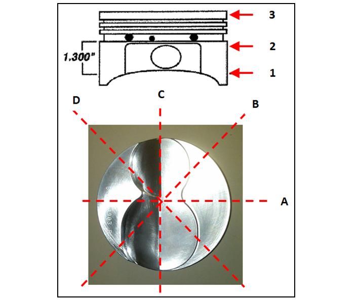
The piston OD measurements were a little more varied than I expected. Here are the results:
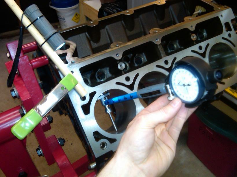
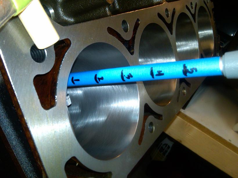
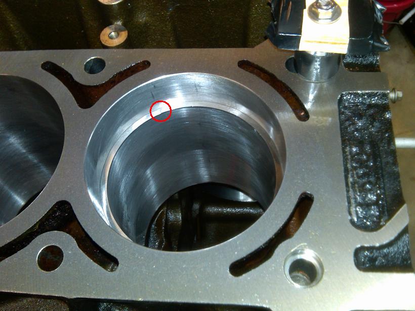
Now to measure the cylinder bores with the dial bore gauge. I didn't have any torque plates, so my measurements are likely not totally accurate once the heads are bolted on. I made an assumption that the smallest cylinders without the torque plates, would still be the smallest cylinders after the heads are bolted on. Not sure if this is 100% correct, however this is how I carried on. An alternative would be to bolt on the heads and measure from the bottom as Ckpitt did in his build.
Here are the pics. I made depth graduations on the dial bore gauge and mocked up a small flashlight so I could see the shadow on the bore gauge to know now deep it was.
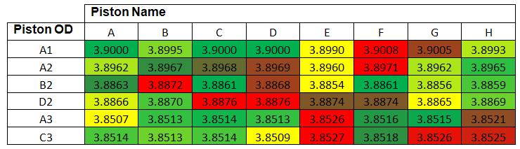
Here are the bore dimensions:
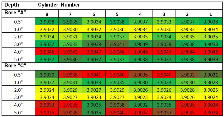
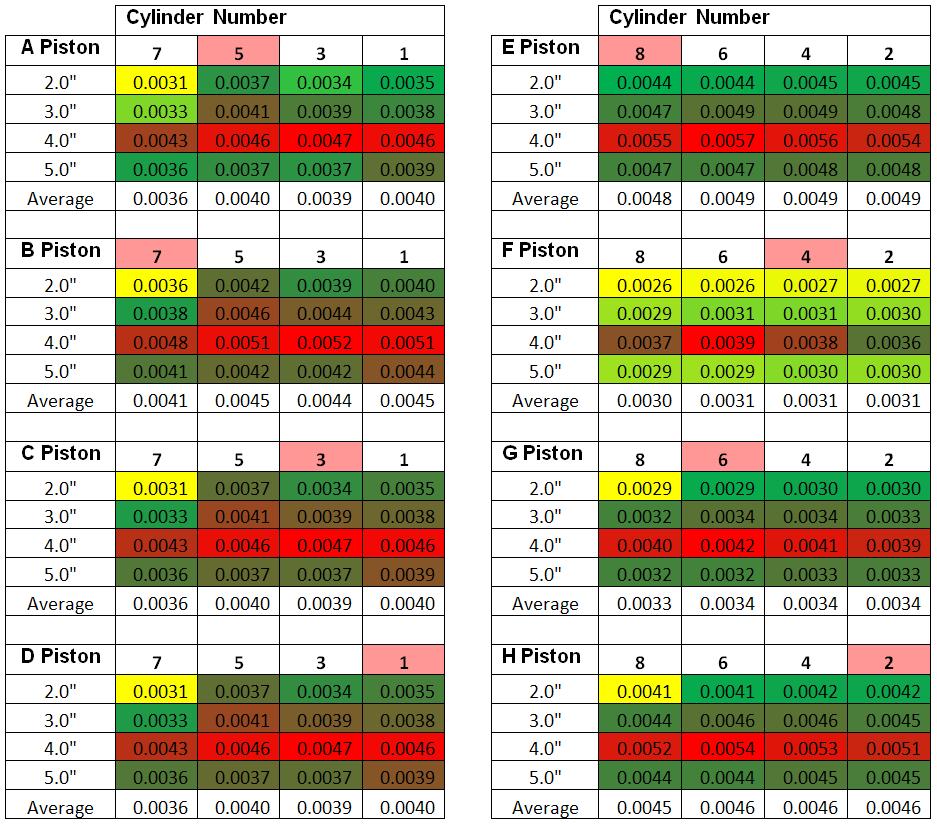
Here is the chart showing all possible cylinder matching combinations and the resulting clearances. These clearances are calculated from the "A1" piston OD dimension, as this is the widest part of the piston. The matches are shown in Pink.

My references for ideal iron block main clearances range from 0.0024" - 0.0031", all from reputable sources. I determined that all except for #2 were too tight for my liking so I substituted those lower half shells with HX bearings. The re-measured clearances are shown below.

I kept the left-over bearing shells in storage for use later.

Then it was time to measure the connecting rod bearing clearances. The methodology is pretty much the same. While the crank was still out, I measured the rod journals with the 2-3" micrometer. Here are the results.

Here are the dimensions of the selected rod bolt. ARP 8740 material.

In order to measure the free-standing length of each rod bolt, I calibrated the rod bolt stretch gauge to read ZERO when the 2" standard was installed straight.

Then the free length and installed length of each rod bolt was measured. The rods were named A through H. I didn't use numbers because at this point I was aiming to match the rods with the best fitting locations on the crankshaft. Unlike the mains, the rods are not tied to any one spot on the crankshaft.


Here are the measurements of each rod bolt. The "t" denotes the bolt that was adjacent the bearing tangs. As you can see, the initial torquing of 63 lb-ft (per ARP instructions) resulted in less stretch than the ARP specification of 0.0059" - 0.0063". Because of this discrepancy, it was decided to re-torque each rod bolt until a higher stretch was achieved. After the 85 lb-ft was applied, the bolts were checked again for free length to ensure there was no permanent stretch. There was none.

A basic stress analysis was done for the rod bolts as explained here:
http://www.scribd.com/doc/160936551/...d-Bolt-Preload
After the correct torque was selected, the ID of each rod bearing was measured with the dial bore gauge. Just FYI, the clearances did not change between the 63 lb-ft and 85 lb-ft input torque on the rod caps.

Here are the measured ID's of each rod big end (with bearing):

Recommended rod bearing clearances range from 0.0016" - 0.0026" taken from reputable sources. To assign each rod to the best fitting location on the crank shaft, all possibilities were calculated and charted as shown below. Yellow is low value, Green is medium, Red is high. The black boxes indicate the chosen parings.

As can be seen above, the values for "Rod A" were too low for my liking. A single HX bearing half shell was swapped over and resulted in a clearance range of 0.0020" - 0.0030". This was chosen for the build.
Next it was time to assign each piston to the best fitting cylinder, just like the rods. The pistons were each measured with a 3-4" micrometer as shown:


The piston OD measurements were a little more varied than I expected. Here are the results:

Now to measure the cylinder bores with the dial bore gauge. I didn't have any torque plates, so my measurements are likely not totally accurate once the heads are bolted on. I made an assumption that the smallest cylinders without the torque plates, would still be the smallest cylinders after the heads are bolted on. Not sure if this is 100% correct, however this is how I carried on. An alternative would be to bolt on the heads and measure from the bottom as Ckpitt did in his build.
Here are the pics. I made depth graduations on the dial bore gauge and mocked up a small flashlight so I could see the shadow on the bore gauge to know now deep it was.


Here are the bore dimensions:

Here is the chart showing all possible cylinder matching combinations and the resulting clearances. These clearances are calculated from the "A1" piston OD dimension, as this is the widest part of the piston. The matches are shown in Pink.

Last edited by RezinTexas; Aug 25, 2013 at 05:14 AM.
Jul 28, 2013 | 09:35 AM
#6
Thread Starter
TECH Fanatic
Joined: Jun 2011
Posts: 1,292
Likes: 5
From: Houston
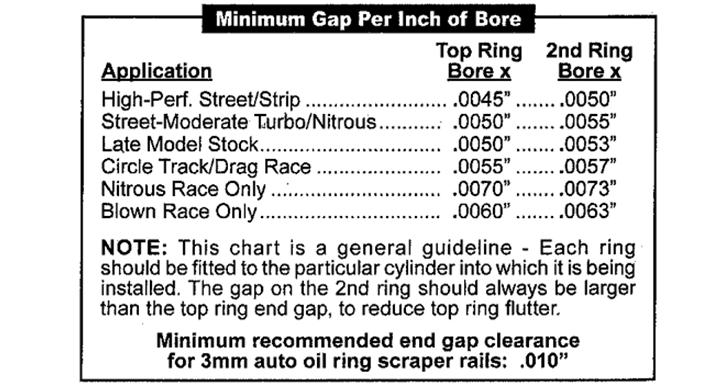
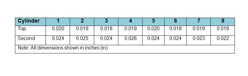
Next I file fit each ring to its cylinder. Out of the box, the rings will have no gap as shown here:
Here is the ring gap chart from Wiseco. My target was 0.018" Top ring and 0.022" Lower ring.
I started grinding with this tool to achieve the right gap.
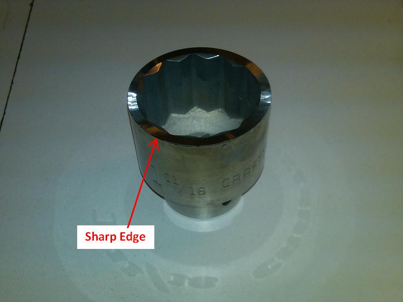
When installing the ring to check the gap, you need a squaring tool. This is a very cheap tool to buy, however I made my own version that put the ring at 1" deep in the cylinder. This depth corresponded to the narrowest cylinder bore dimension that I had previously measured. The tool is just a simple socket bolted to a small piece of wood.
Moving my hand in a circular pattern made it work.
Here is how I checked to ensure proper gap after all the filing was done:
Here are the final gaps as-measured. Some are a little higher than my target.
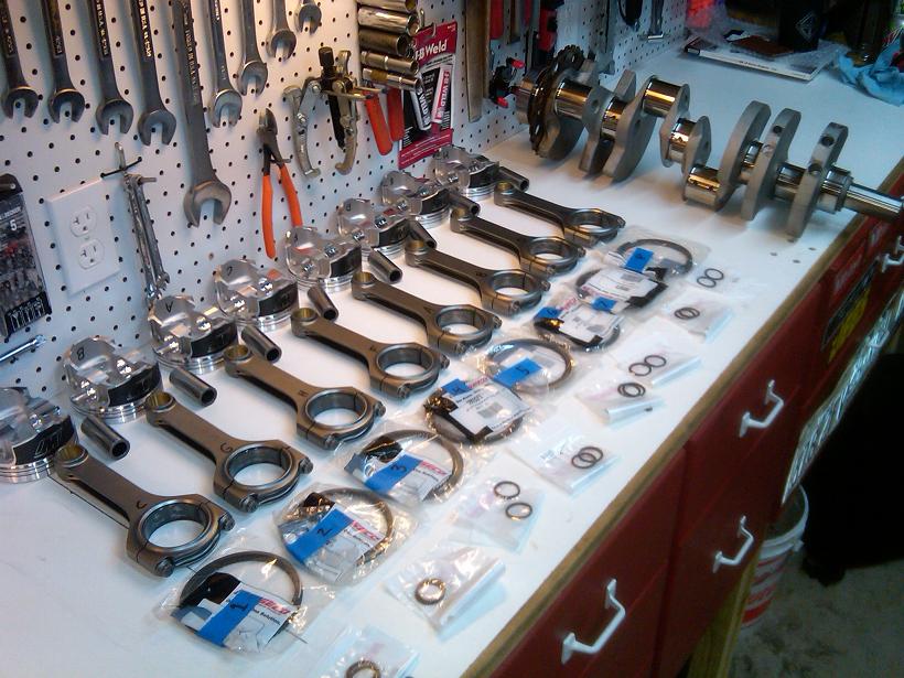
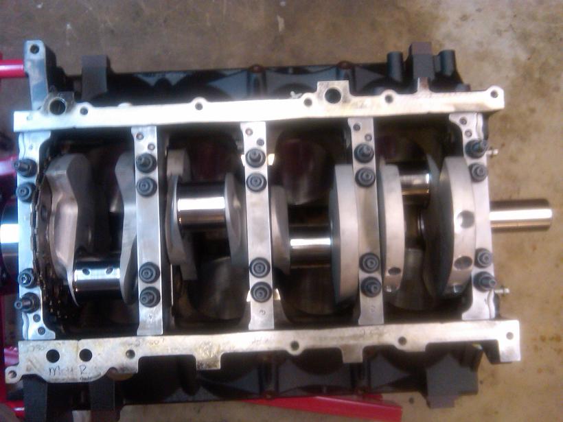
Now the entire rotating assembly is completely matched, balanced, and ready to install!
Bearings lubed:
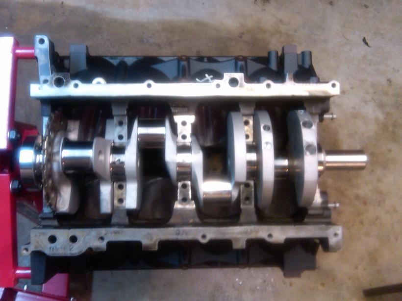
Crank set:
Caps torqued:
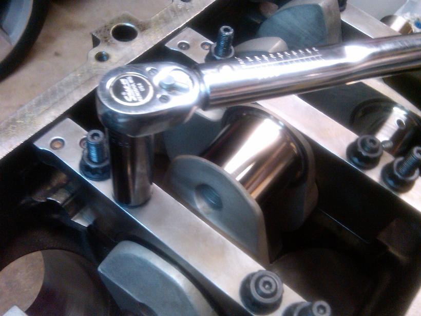
A little black RTV under the head of the side bolts.
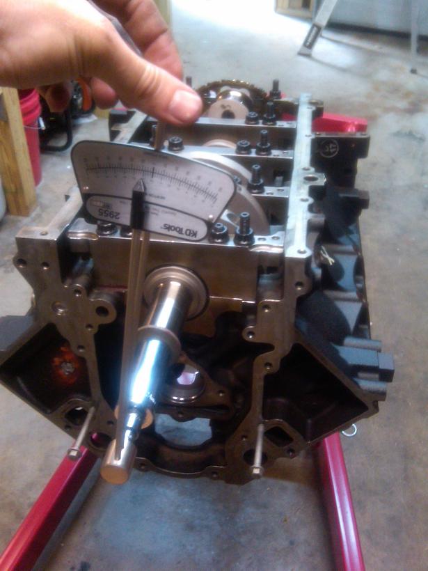
Crank-only turning resistance checked with beam-type in-lb torque wrench. Turning resistance was around 18-20 in-lb and smooth as glass.
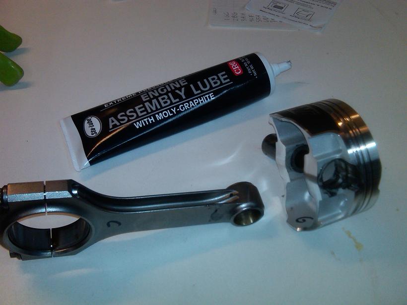
Next I assembled the pistons to the rods, and piston rings.
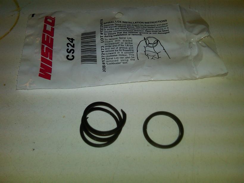
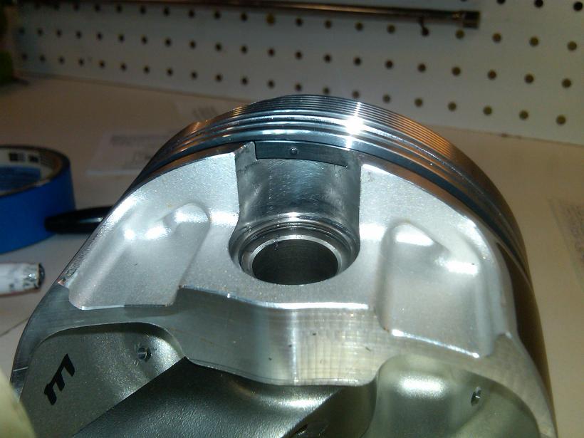
Sprio locks stretched for install:
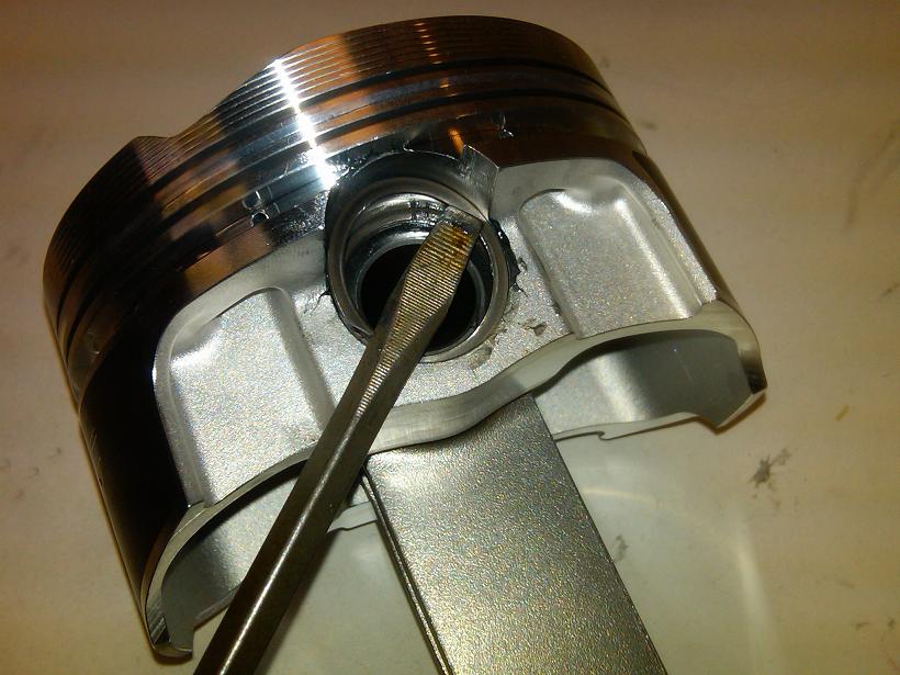
This picture shows the installed spiro lock, and also the underside of the groove lock spacer ring. Note the position of the small indent per the instructions.
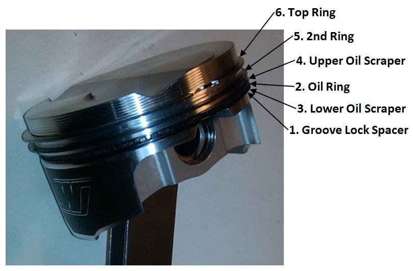
This image shows the stackup and assembly order of the various piston rings.

Here is the ring gap chart from Wiseco. My target was 0.018" Top ring and 0.022" Lower ring.

I started grinding with this tool to achieve the right gap.

When installing the ring to check the gap, you need a squaring tool. This is a very cheap tool to buy, however I made my own version that put the ring at 1" deep in the cylinder. This depth corresponded to the narrowest cylinder bore dimension that I had previously measured. The tool is just a simple socket bolted to a small piece of wood.

Moving my hand in a circular pattern made it work.

Here is how I checked to ensure proper gap after all the filing was done:

Here are the final gaps as-measured. Some are a little higher than my target.

Now the entire rotating assembly is completely matched, balanced, and ready to install!


Bearings lubed:

Crank set:

Caps torqued:


A little black RTV under the head of the side bolts.

Crank-only turning resistance checked with beam-type in-lb torque wrench. Turning resistance was around 18-20 in-lb and smooth as glass.

Next I assembled the pistons to the rods, and piston rings.

Sprio locks stretched for install:


This picture shows the installed spiro lock, and also the underside of the groove lock spacer ring. Note the position of the small indent per the instructions.

This image shows the stackup and assembly order of the various piston rings.

Last edited by RezinTexas; Aug 27, 2013 at 06:14 AM.
Jul 28, 2013 | 09:36 AM
#7
Thread Starter
TECH Fanatic
Joined: Jun 2011
Posts: 1,292
Likes: 5
From: Houston
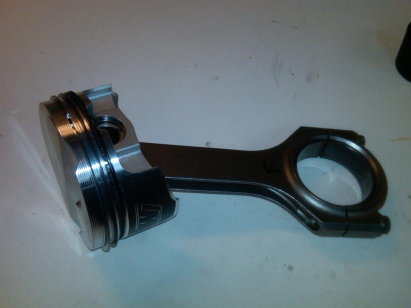
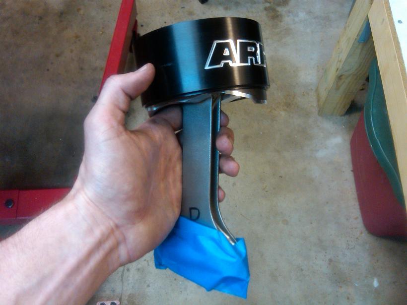
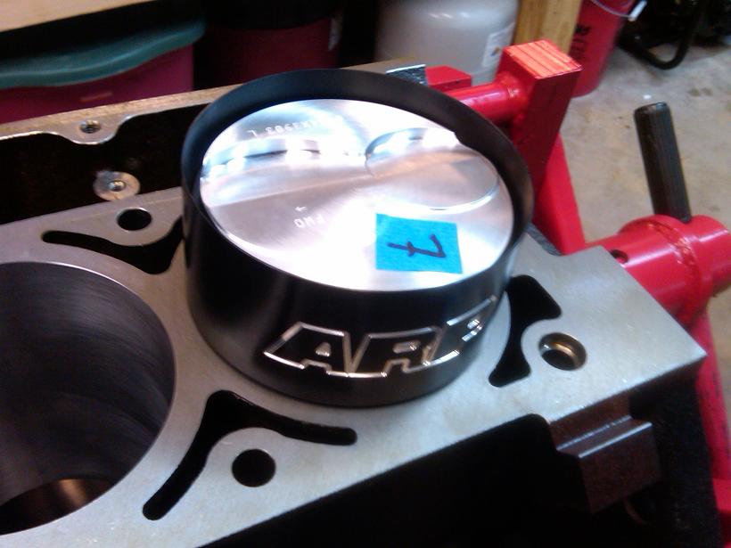
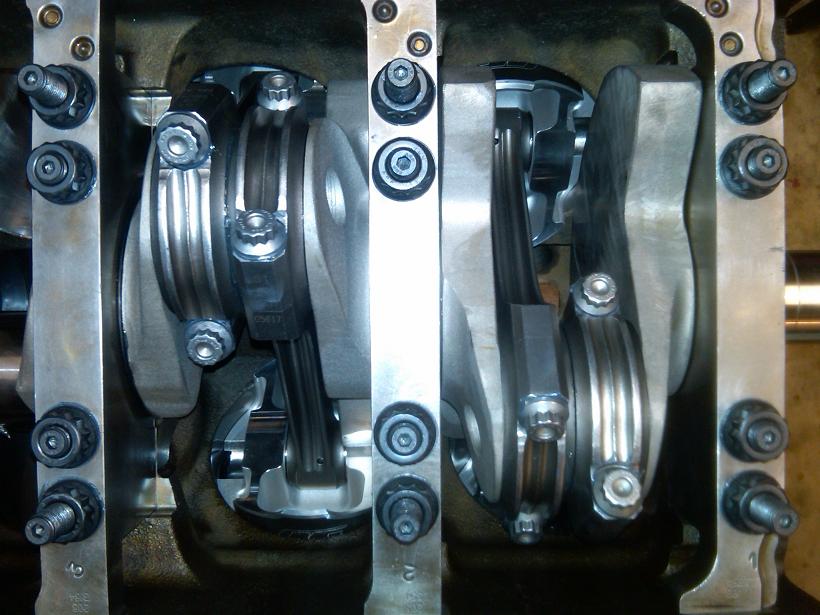
Now the piston & rod assemblies are ready to be installed.
I lubed the bearings as shown:
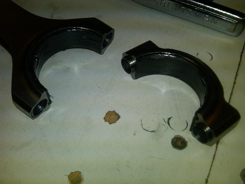
Using the ARP 3.900" ring compressor tool. Worked perfectly. The tape on the rod big end is to prevent scratches on the cylinder walls during installation. This is easily removed after the piston is installed.
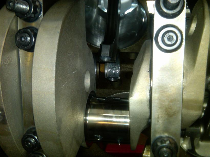
Confirming correct rod bolt stretch after assembly. As a point of interest, the bolt stretch values for each rod bolt were 0.0005" - 0.0010" HIGHER when the connecting rods were loose vs. installed on the crank shaft.
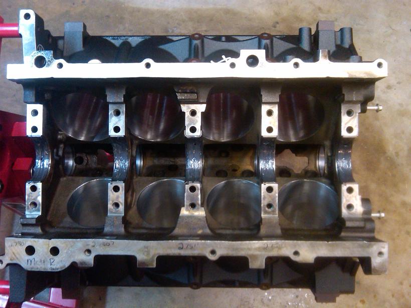
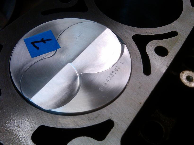
Finished pics:
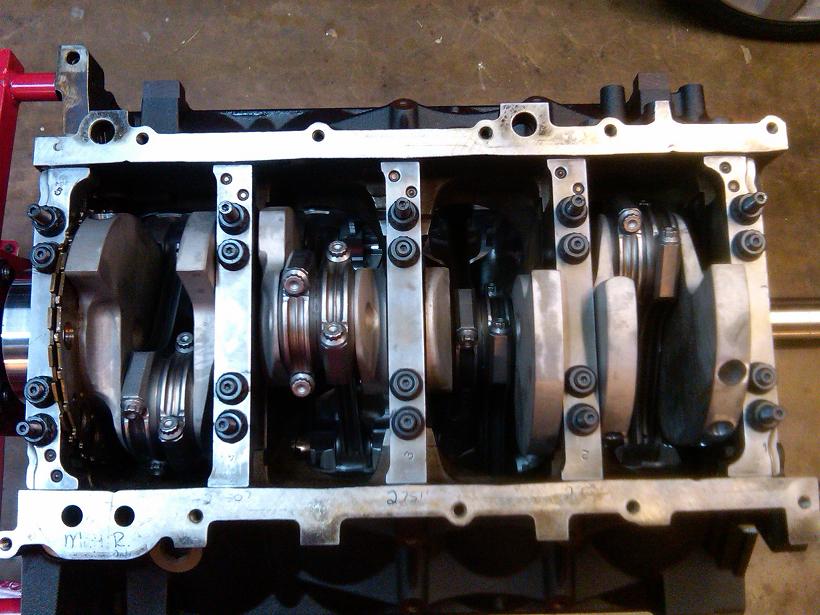
As a side note, I decided to replace the Cam bearings (prior to rotating assembly installation). This turned out to be a mistake, and I do not recommend doing this unless the OEM bearings are damaged. The exposed copper is not an issue, they come like this from the line honing at the factory.
Anyway, I used a modified large socket to push out the OEM bearings.
Pushing in the new bearings:
Confirming oiling hole alignment:
Final cam bearing clearance numbers. I used Sealed Power 1898M bearings, the fitment was not good (very tight) at first so I opened up the clearances with some 2000# sand paper.
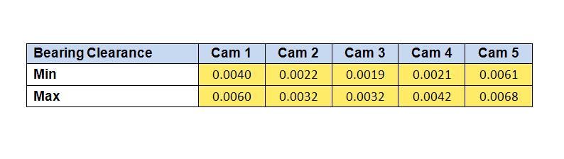
As you can see, the clearances are very high. GM spec is up to 0.006". In the end it didn't matter, the hot idle oil pressure is still 50-60 psi with M1 0-40 oil. I speculate that cam bearing clearance is not nearly as critical as main/rod clearances. This may be because the oiling hole is very small, and the forces exerted on the camshaft are significantly smaller than the crank/rods.

I lubed the bearings as shown:

Using the ARP 3.900" ring compressor tool. Worked perfectly. The tape on the rod big end is to prevent scratches on the cylinder walls during installation. This is easily removed after the piston is installed.


Confirming correct rod bolt stretch after assembly. As a point of interest, the bolt stretch values for each rod bolt were 0.0005" - 0.0010" HIGHER when the connecting rods were loose vs. installed on the crank shaft.

Finished pics:


As a side note, I decided to replace the Cam bearings (prior to rotating assembly installation). This turned out to be a mistake, and I do not recommend doing this unless the OEM bearings are damaged. The exposed copper is not an issue, they come like this from the line honing at the factory.
Anyway, I used a modified large socket to push out the OEM bearings.


Pushing in the new bearings:

Confirming oiling hole alignment:

Final cam bearing clearance numbers. I used Sealed Power 1898M bearings, the fitment was not good (very tight) at first so I opened up the clearances with some 2000# sand paper.

As you can see, the clearances are very high. GM spec is up to 0.006". In the end it didn't matter, the hot idle oil pressure is still 50-60 psi with M1 0-40 oil. I speculate that cam bearing clearance is not nearly as critical as main/rod clearances. This may be because the oiling hole is very small, and the forces exerted on the camshaft are significantly smaller than the crank/rods.
Last edited by RezinTexas; Aug 25, 2013 at 06:48 AM.
Trending Topics
Jul 28, 2013 | 09:36 AM
#8
Thread Starter
TECH Fanatic
Joined: Jun 2011
Posts: 1,292
Likes: 5
From: Houston
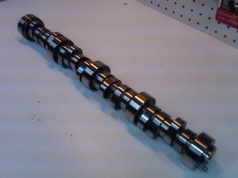
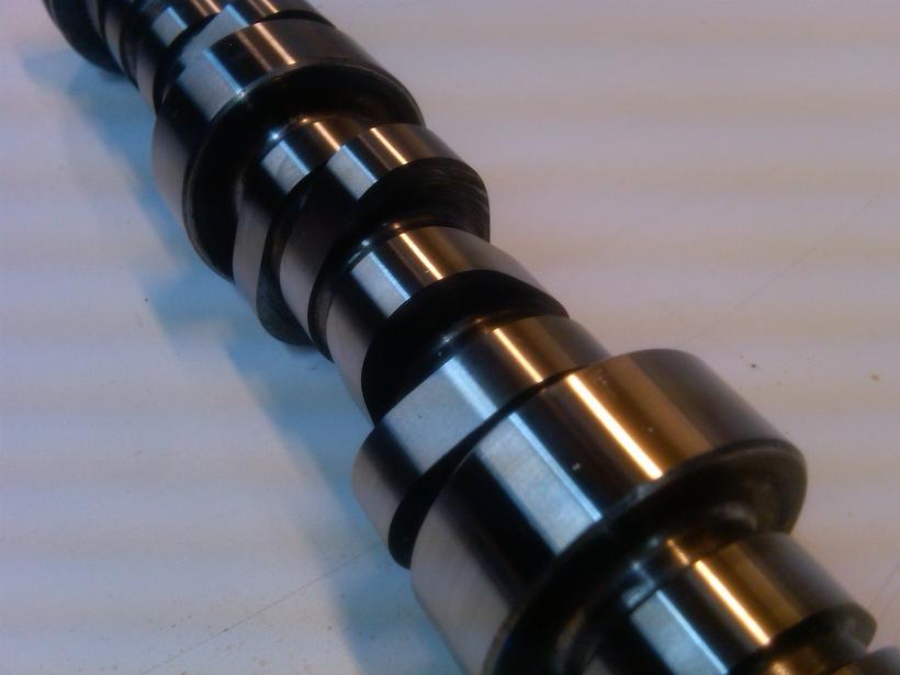
Here is the Patrick G custom cam specification.
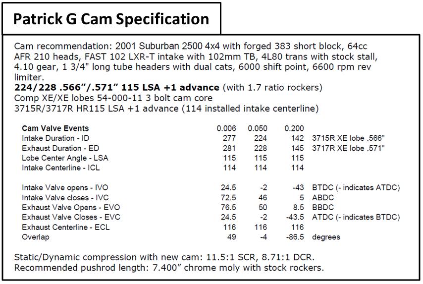
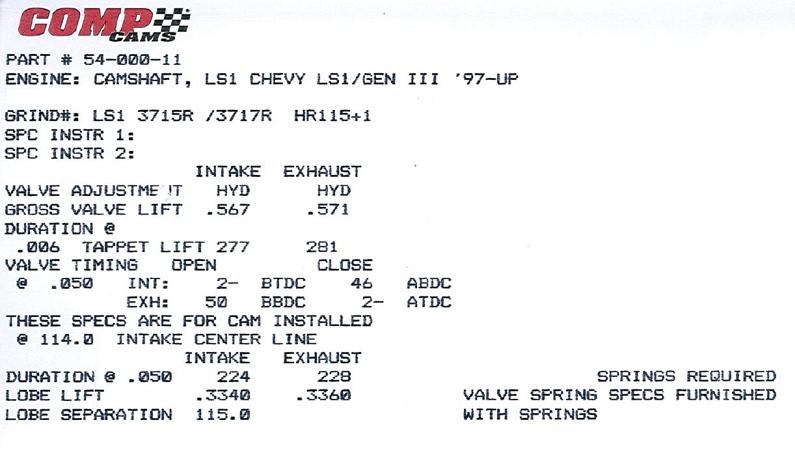
Here is the cam card. The cam was sourced through Geoff at EPS.
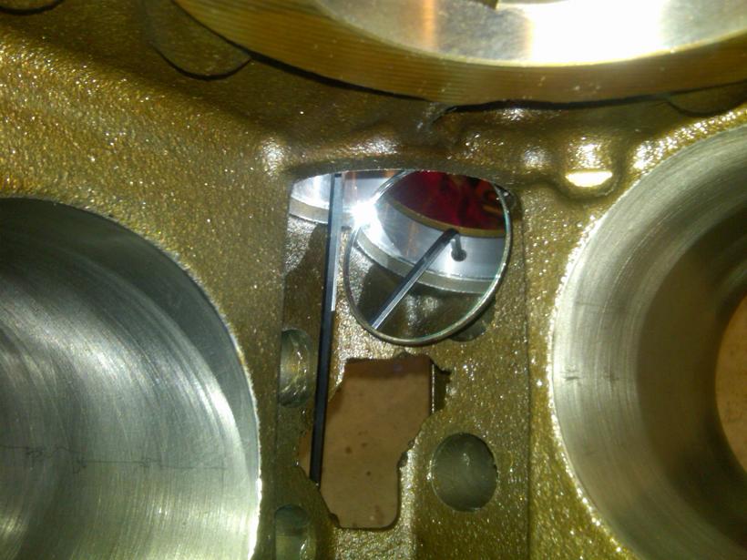
Checking camshaft thrust clearance. Use a feeler gauge here.
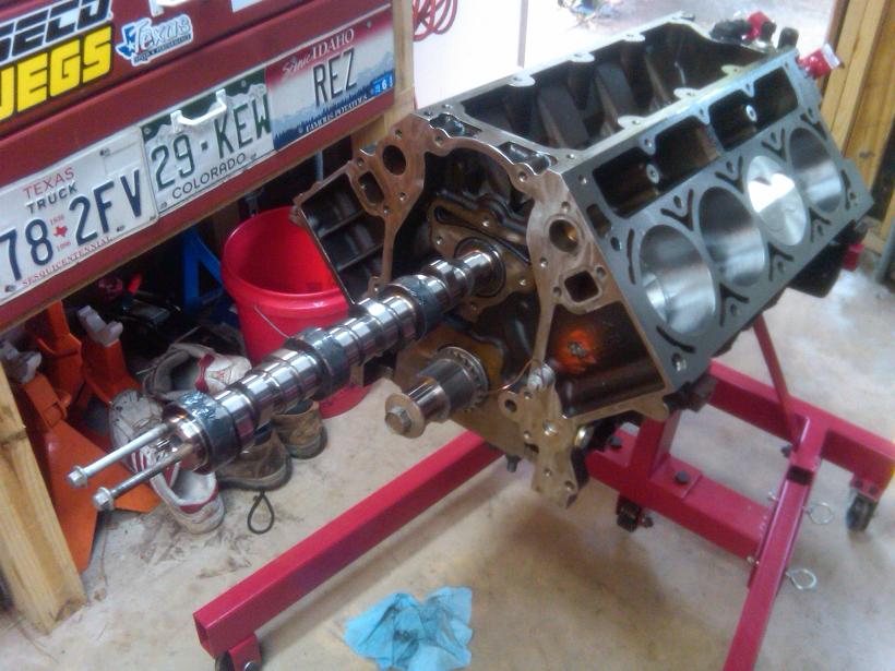
Installing new camshaft into short block.
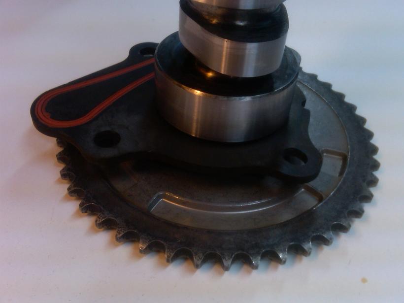
Cam retainer plate.
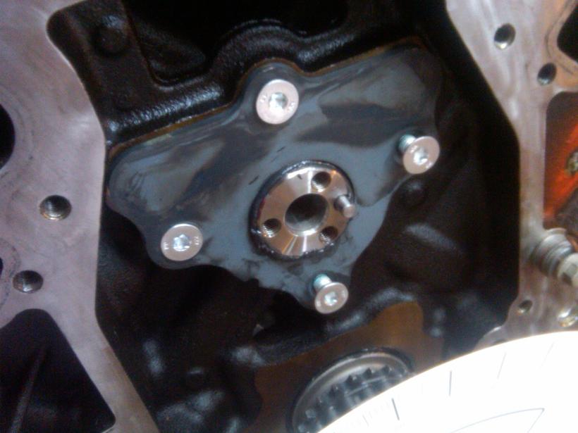
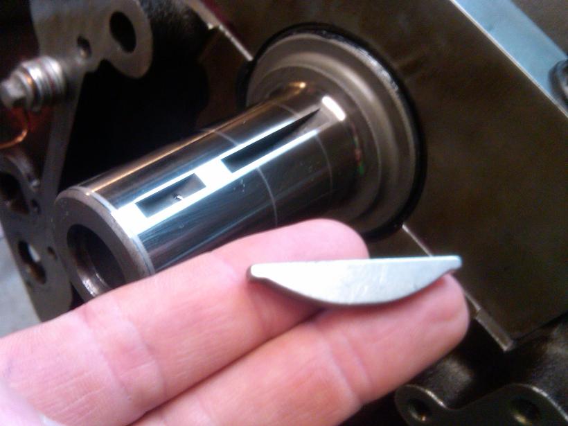
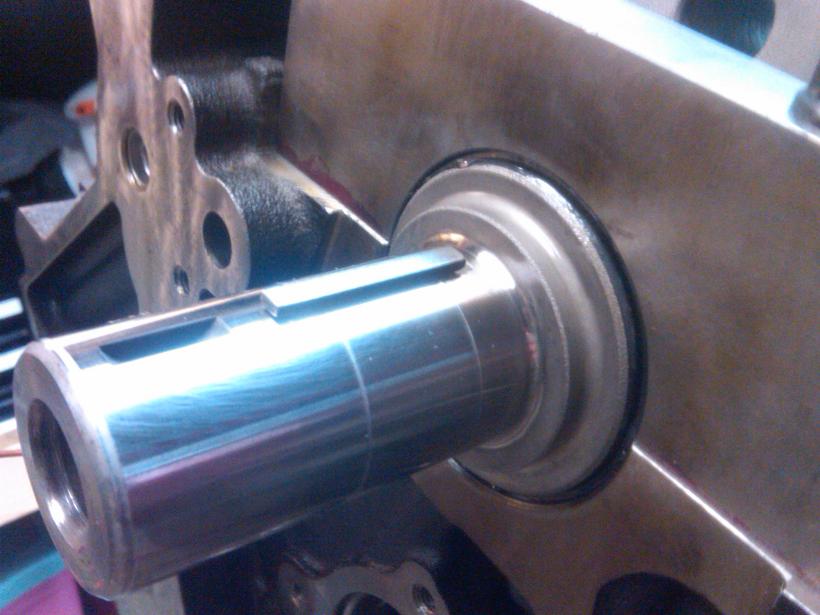
New crank keyway:
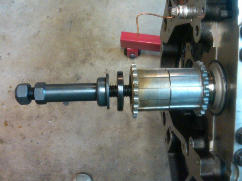
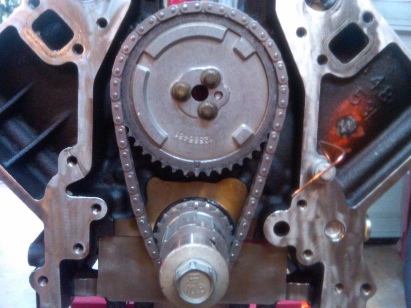
Installing timing gear with hawk tool. I used the ARP crank washer and an old timing gear as spacers.
Installing cam gear with ARP bolts. Red Loctite used here.
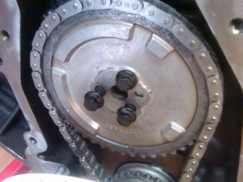
Dot to Dot. This is an OEM LS2 timing set.
Now to check the camshaft lobe timing. Because my timing set is non-adjustable, I can't really "degree" the camshaft, however I thoroughly checked all lobe timing events to ensure there were no major problems. Everything was within reasonable tolerances.
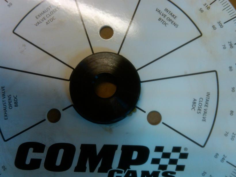
I started by gluing the ARP crank bolt washer to the degree wheel. This is so the wheel will be centralized on the crank bolt. A tapered washer is another way to do this. Some degree kits come with the tapered washer.
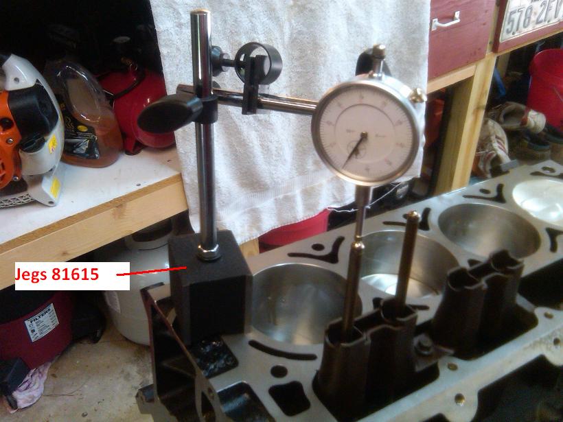
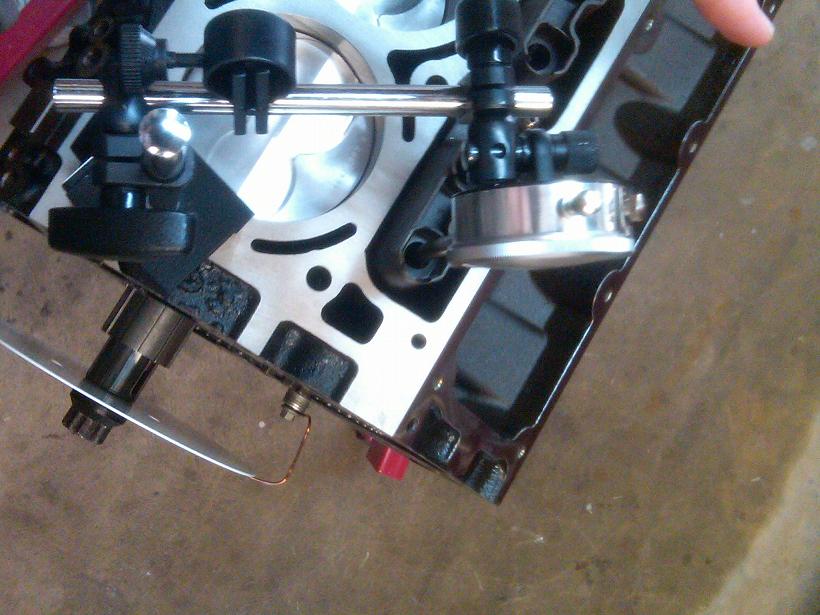
Need to find cylinder #1 TDC. The setup below was used. A copper wire was rigged up to point to Zero when cylinder #1 was at exact TDC.
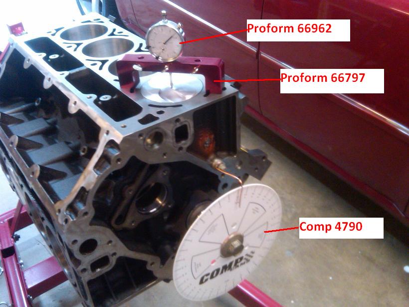
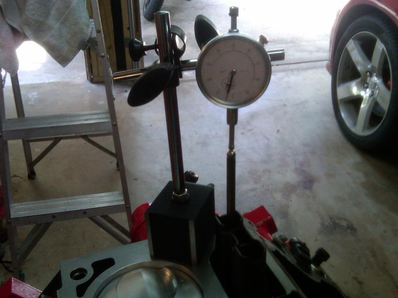
Here are a few pics of the lobe measuring process. I used regular new lifters, pushrod, and inverted lifter tray. There is no need for solid lifters here, as the spring force in the dial indicator is very weak and easily overcome by the un-modified lifters. The inverted lifter tray was helpful to hold the pushrod upright while getting things setup.
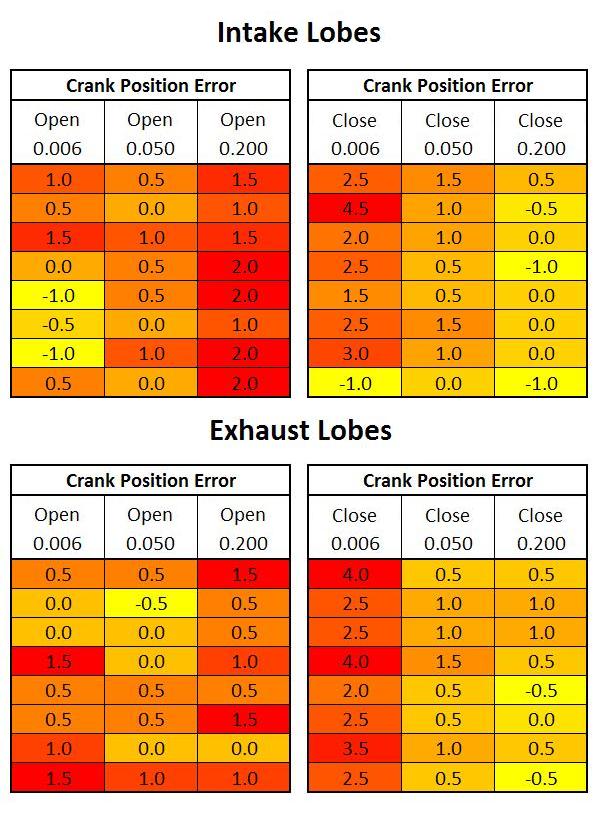
Each cam lobe was measured in 6 places and compared to the specification. Here are the error figures. Yellow is low, orange is medium, and red is high error. I don't know what is good here, but this doesn't look too bad. Some of the error is likely due to the fact that the cam is advanced +1 degree, although I installed it dot-dot.
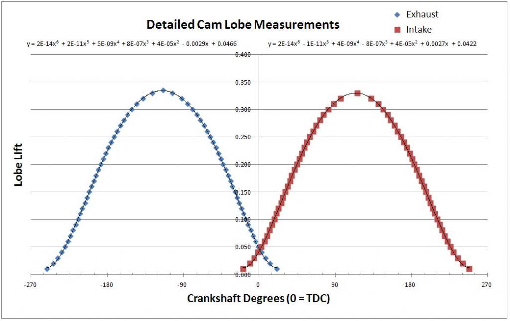
I also took detailed readings from 1 pair of lobes. Here is the plot just for fun.
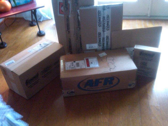
Then I got a lot of new boxes in the mail...

Here is the cam card. The cam was sourced through Geoff at EPS.


Checking camshaft thrust clearance. Use a feeler gauge here.

Installing new camshaft into short block.

Cam retainer plate.

New crank keyway:


Installing timing gear with hawk tool. I used the ARP crank washer and an old timing gear as spacers.

Installing cam gear with ARP bolts. Red Loctite used here.

Dot to Dot. This is an OEM LS2 timing set.

Now to check the camshaft lobe timing. Because my timing set is non-adjustable, I can't really "degree" the camshaft, however I thoroughly checked all lobe timing events to ensure there were no major problems. Everything was within reasonable tolerances.
I started by gluing the ARP crank bolt washer to the degree wheel. This is so the wheel will be centralized on the crank bolt. A tapered washer is another way to do this. Some degree kits come with the tapered washer.

Need to find cylinder #1 TDC. The setup below was used. A copper wire was rigged up to point to Zero when cylinder #1 was at exact TDC.

Here are a few pics of the lobe measuring process. I used regular new lifters, pushrod, and inverted lifter tray. There is no need for solid lifters here, as the spring force in the dial indicator is very weak and easily overcome by the un-modified lifters. The inverted lifter tray was helpful to hold the pushrod upright while getting things setup.


Each cam lobe was measured in 6 places and compared to the specification. Here are the error figures. Yellow is low, orange is medium, and red is high error. I don't know what is good here, but this doesn't look too bad. Some of the error is likely due to the fact that the cam is advanced +1 degree, although I installed it dot-dot.

I also took detailed readings from 1 pair of lobes. Here is the plot just for fun.

Then I got a lot of new boxes in the mail...

Last edited by RezinTexas; Aug 25, 2013 at 09:01 AM.
Jul 28, 2013 | 09:37 AM
#9
Thread Starter
TECH Fanatic
Joined: Jun 2011
Posts: 1,292
Likes: 5
From: Houston
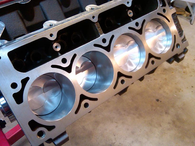
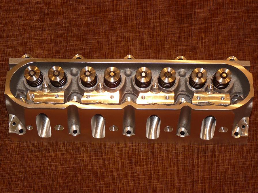
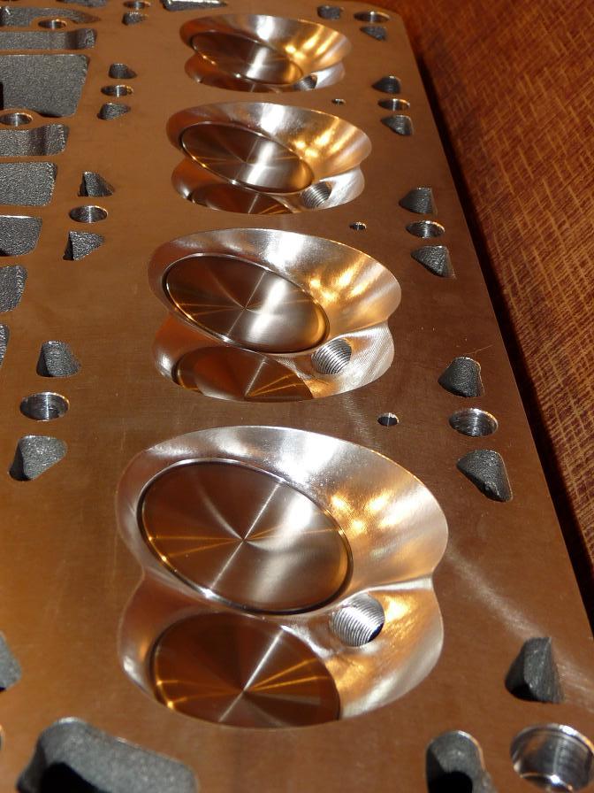
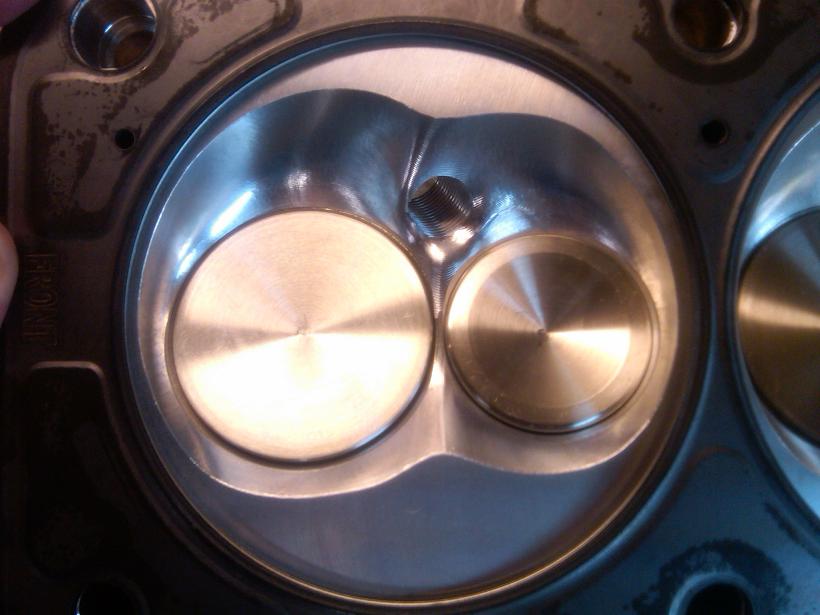
Here are some shots of the heads. New AFR 210 V2's milled to 63cc.
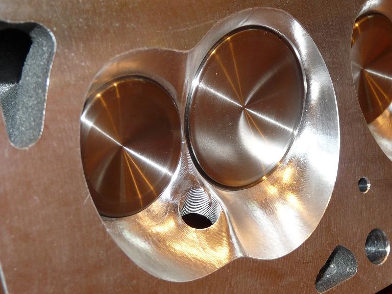
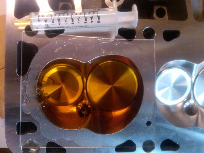
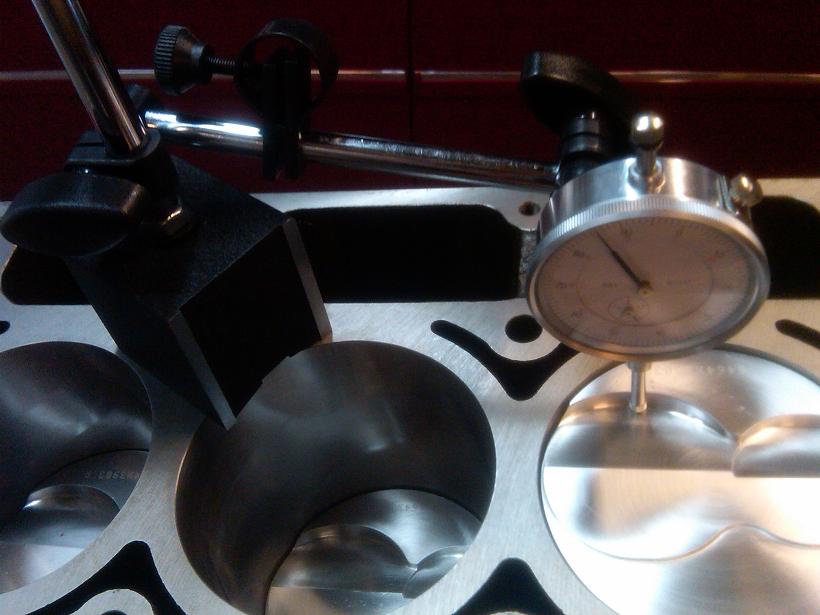
I measured the volume of the combustion chambers. 63cc on the dot!
Measuring piston deck heights so I know what head gaskets to buy. As it turned out, the block deck was incorrectly machined at HKE. I had one side 0.007" off from the other side. I compensated for this with different thickness head gaskets to equalize the quench and compression ratios on each bank.
I also measured the height at the piston edges. I rocked the pistons by hand, took high and low measurements, then took the average. These numbers matched what I got for the center measurements.

Cometic 4.135" bore gaskets alignment with heads.
Alignment with block.
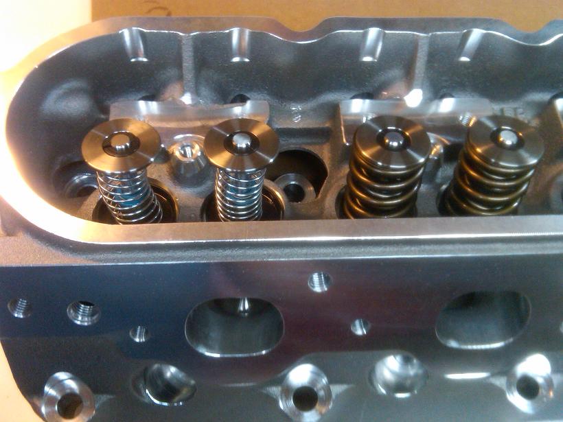
Removing a pair of valve springs.
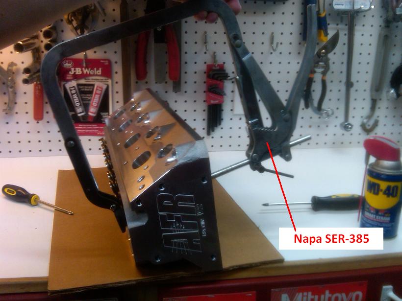
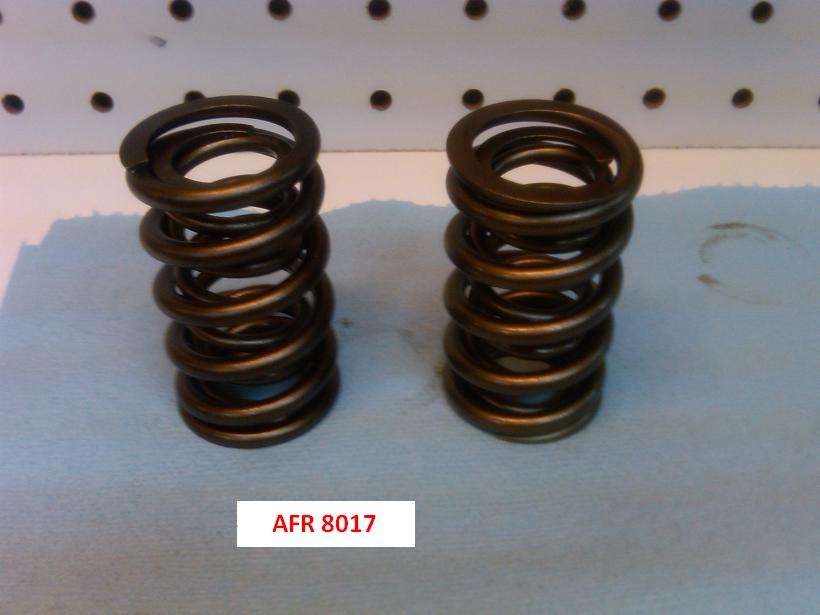
Checker springs installed.
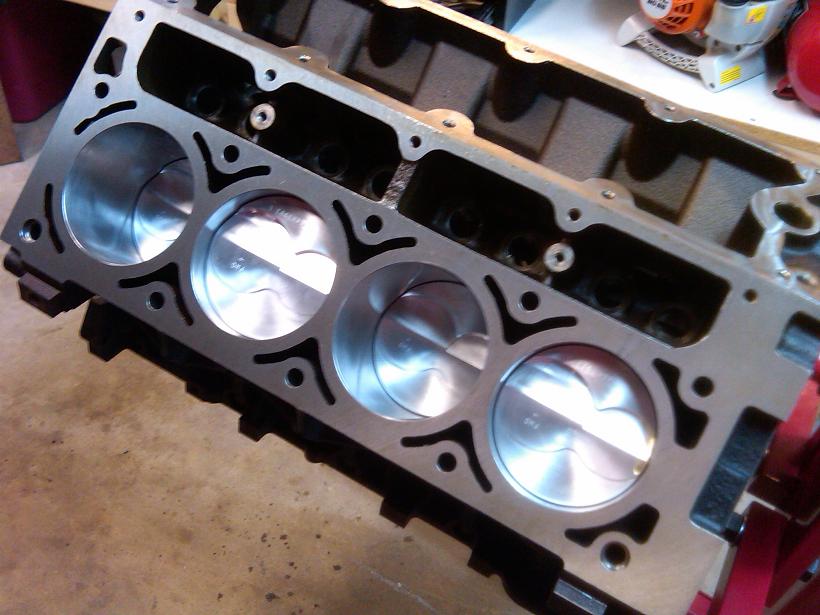
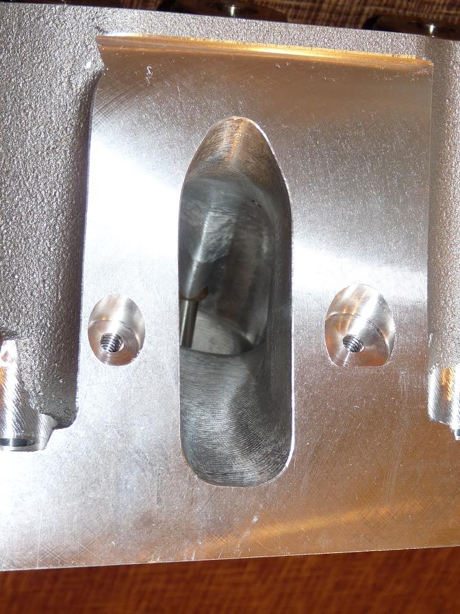
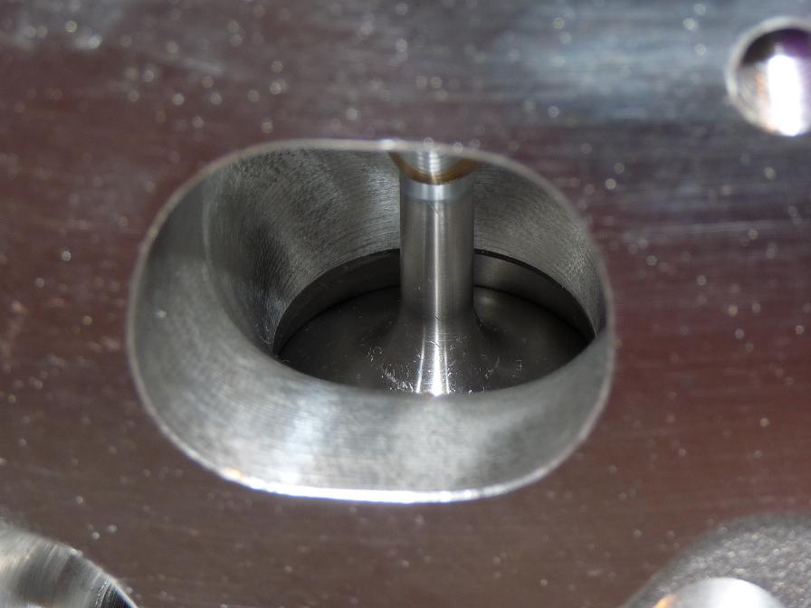
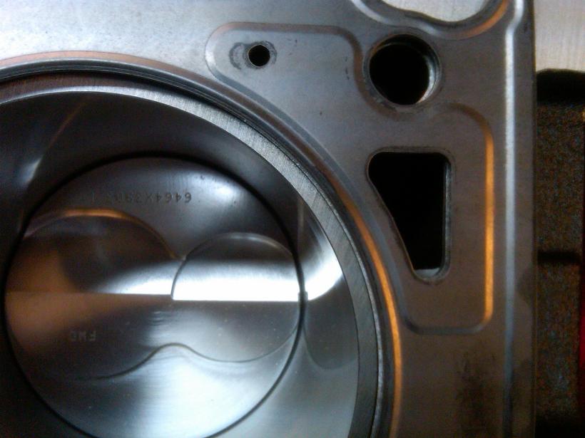
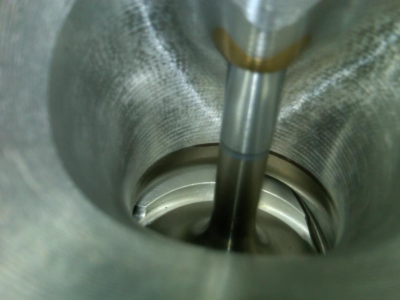
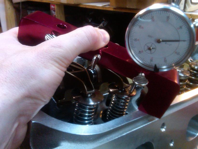
Here is a view of the exhaust valve interfacing with the piston valve relief with the head bolted on.
Adjustable length pushrod installed for PTV checking.
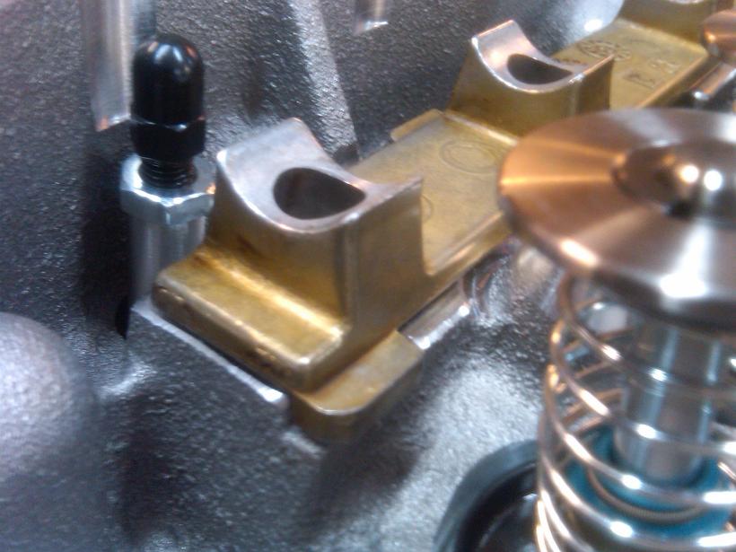
Rocker arm installed, pushrod adjusted to zero lash. I held the bridge stand firmly in place and cycled the crankshaft. I retained the cylinder #1 TDC reference from earlier and was able to get PTV clearance numbers by stroking the valve by hand after a few degrees of crank rotation.
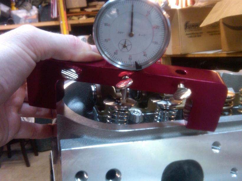
The PTV measuring process is explained further here:
http://www.scribd.com/doc/137049285/...RAFT-20-Apr-13
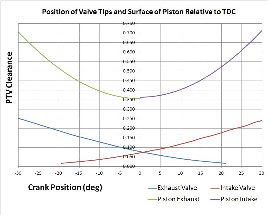
Here are the measured values. Plenty of PTV clearance here. I also calculated what the PTV clearance would be by taking some additional measurements. The calculated values were close to what my measured values were.
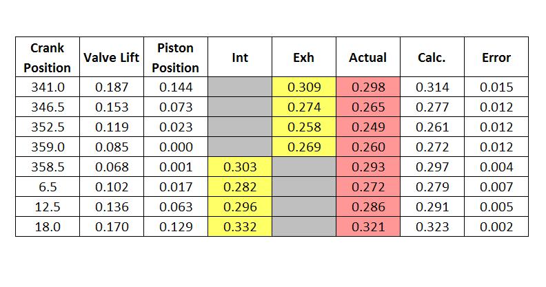
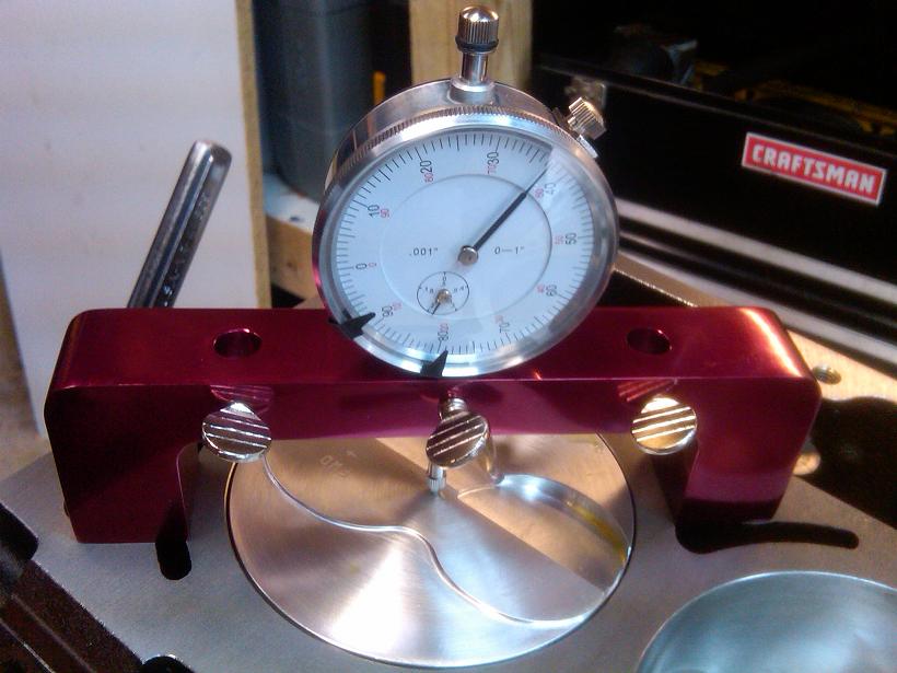
Measuring the depth of the valve relief.
Here is a graph of the result. This shows the position of the bottom of the piston valve relief relative to the position of the valve tip. This is very useful to understand how PTV clearance works on these engines.


I measured the volume of the combustion chambers. 63cc on the dot!

Measuring piston deck heights so I know what head gaskets to buy. As it turned out, the block deck was incorrectly machined at HKE. I had one side 0.007" off from the other side. I compensated for this with different thickness head gaskets to equalize the quench and compression ratios on each bank.

I also measured the height at the piston edges. I rocked the pistons by hand, took high and low measurements, then took the average. These numbers matched what I got for the center measurements.

Cometic 4.135" bore gaskets alignment with heads.

Alignment with block.

Removing a pair of valve springs.


Checker springs installed.

Here is a view of the exhaust valve interfacing with the piston valve relief with the head bolted on.

Adjustable length pushrod installed for PTV checking.

Rocker arm installed, pushrod adjusted to zero lash. I held the bridge stand firmly in place and cycled the crankshaft. I retained the cylinder #1 TDC reference from earlier and was able to get PTV clearance numbers by stroking the valve by hand after a few degrees of crank rotation.


The PTV measuring process is explained further here:
http://www.scribd.com/doc/137049285/...RAFT-20-Apr-13
Here are the measured values. Plenty of PTV clearance here. I also calculated what the PTV clearance would be by taking some additional measurements. The calculated values were close to what my measured values were.

Measuring the depth of the valve relief.

Here is a graph of the result. This shows the position of the bottom of the piston valve relief relative to the position of the valve tip. This is very useful to understand how PTV clearance works on these engines.

Last edited by RezinTexas; Aug 25, 2013 at 08:56 AM.
Jul 28, 2013 | 09:37 AM
#10
Thread Starter
TECH Fanatic
Joined: Jun 2011
Posts: 1,292
Likes: 5
From: Houston
For 4" stroke applications, its common knowledge on this site to use 2 washers on each main stud under the windage tray to give clearance for the connecting rod bolts.
Another option is to buy a windage tray (aftermarket or GM) that is made for the stroker application.
Here is my write up for solving this issue with a factory LM7 windage tray (GM P/N 12558268) and ARP main studs.
The washers used for this are 3/8" SS cut washers from Home Depot (P/N 436873). Dimensions of the washers are 0.408" ID x 0.821" OD x 0.057" THK. The nuts used here are generic 10mm, also from Home Depot. I plan to use blue loctite on the final assembly.
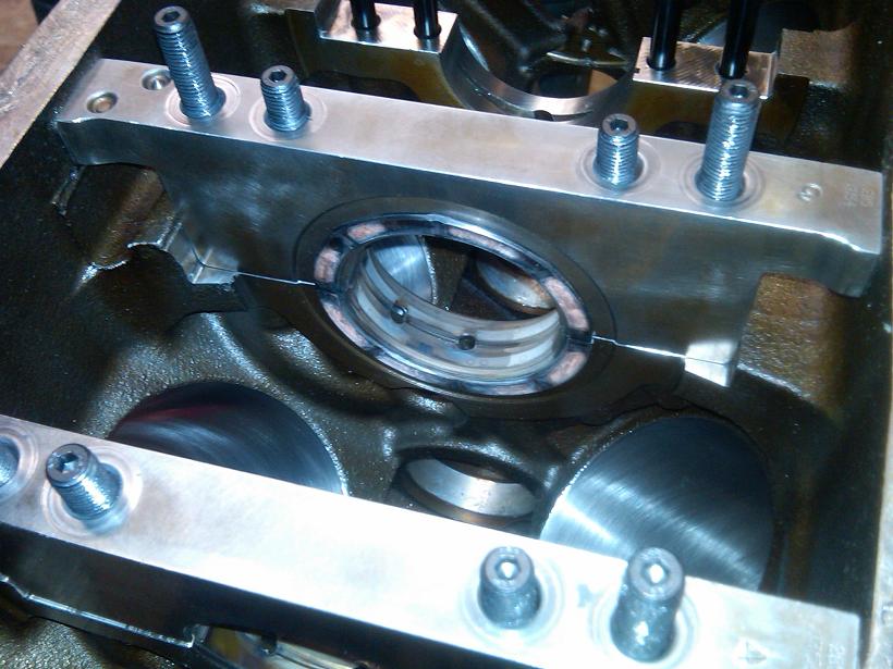
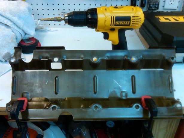
The first thing is to drill out 3 of the bolt holes in the tray that do not fit the 10mm studs. I used a step drill bit at 7/16".
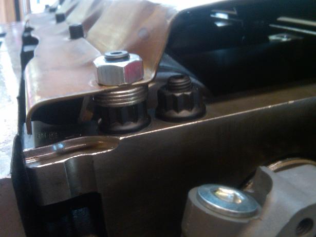
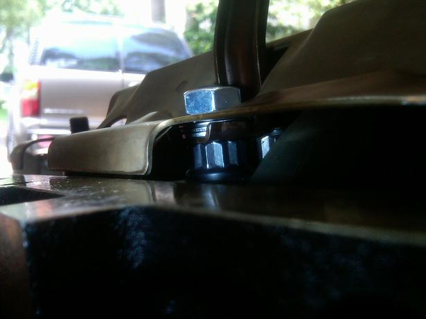
For spacing the tray, I tried the 2 washer method however I was not satisfied with the amount of clearance (my washers are only 0.057" thick, maybe this is why). I opted for 4 washers per stud, which results in ~0.075" minimum clearance as shown below.
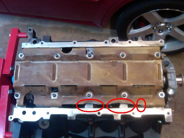
I did a test-fit with the oil pan (without gasket), and there was some interference with the tray. Light clearancing with an angle grinder was required as shown below.
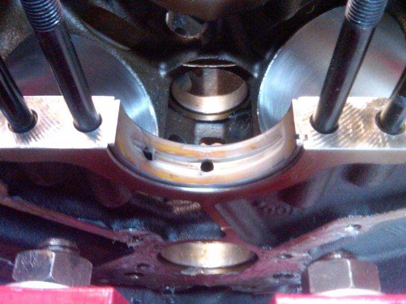
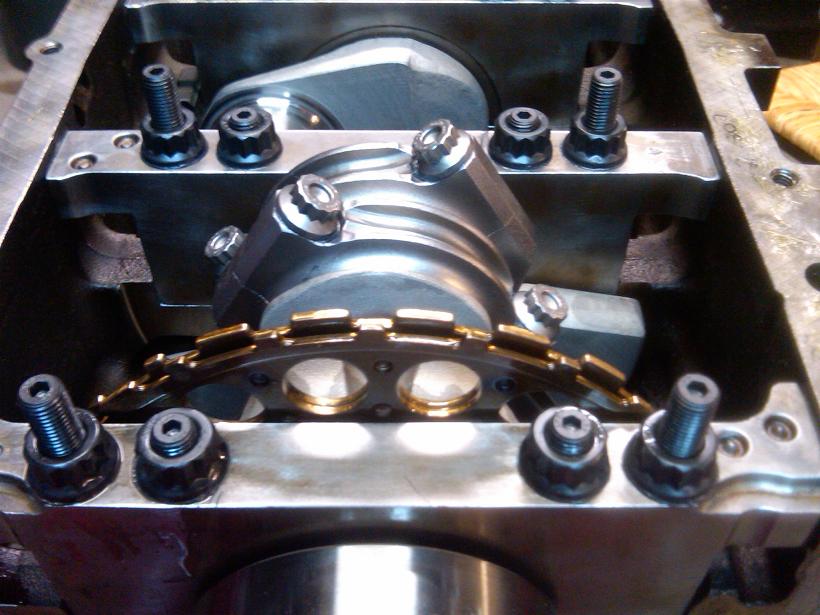
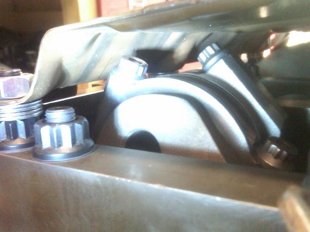
The next issue is of course the pickup tube. My goal was to keep the pickup tube in its original position to ensure no problems at the pickup-oilpan end, or the alignment of the oring to the oil pump at the other end. Here is how I did it.
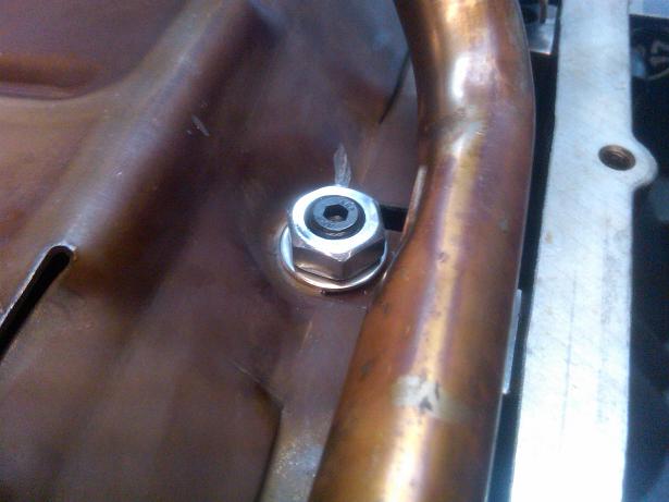
The pickup end support bracket was placed under the windage tray, with 3 washers on top as shown:
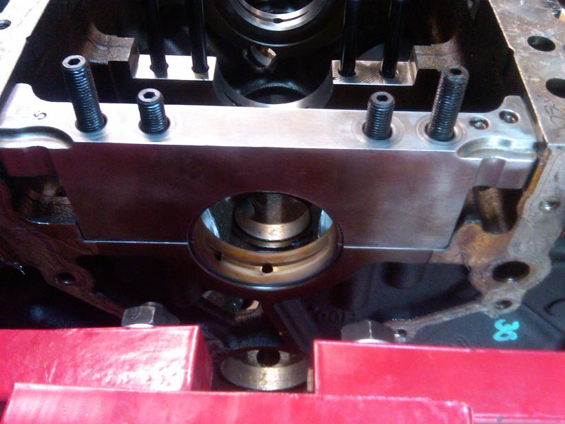
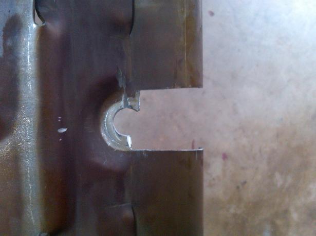
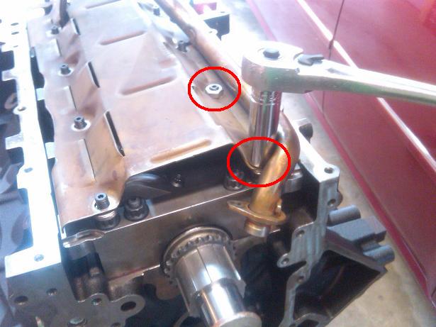
The tray was cut to allow the midpoint support bracket to rest under the tray as shown (2 washers under the bracket):
The tricky part now is to assemble the tray, tube, and oil pump body in the correct sequence to avoid clashing together. After a few attempts, success.
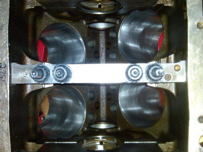
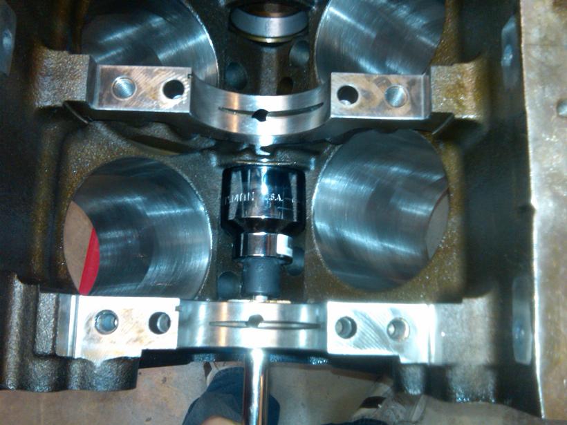
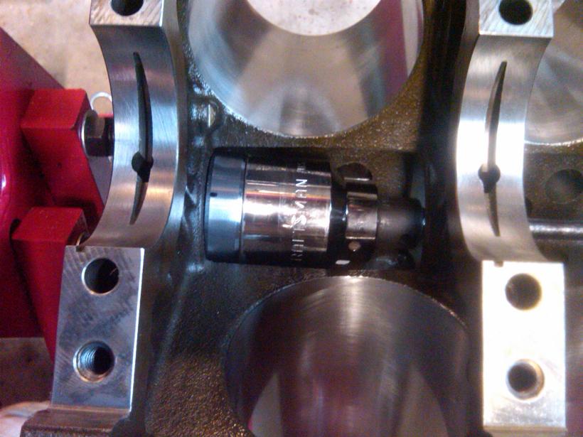
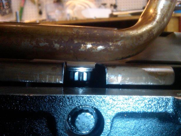
The first step is to assemble the tube/tray/washers as shown (before the oil pump is installed) and tighten only the 2 nuts shown below. This requires pulling the tube to the right side slightly so the socket will fit.
Then install the oil pump body housing/oring and align to the timing gear accordingly. Then tighten down the remaining windage tray nuts.
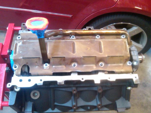
For checking the pickup-oilpan clearance, I used painters tape and orange playdough. The result was .25" clearance without the pan gasket.
Another option is to buy a windage tray (aftermarket or GM) that is made for the stroker application.
Here is my write up for solving this issue with a factory LM7 windage tray (GM P/N 12558268) and ARP main studs.
The washers used for this are 3/8" SS cut washers from Home Depot (P/N 436873). Dimensions of the washers are 0.408" ID x 0.821" OD x 0.057" THK. The nuts used here are generic 10mm, also from Home Depot. I plan to use blue loctite on the final assembly.
The first thing is to drill out 3 of the bolt holes in the tray that do not fit the 10mm studs. I used a step drill bit at 7/16".
For spacing the tray, I tried the 2 washer method however I was not satisfied with the amount of clearance (my washers are only 0.057" thick, maybe this is why). I opted for 4 washers per stud, which results in ~0.075" minimum clearance as shown below.
I did a test-fit with the oil pan (without gasket), and there was some interference with the tray. Light clearancing with an angle grinder was required as shown below.
The next issue is of course the pickup tube. My goal was to keep the pickup tube in its original position to ensure no problems at the pickup-oilpan end, or the alignment of the oring to the oil pump at the other end. Here is how I did it.
The pickup end support bracket was placed under the windage tray, with 3 washers on top as shown:
The tray was cut to allow the midpoint support bracket to rest under the tray as shown (2 washers under the bracket):
The tricky part now is to assemble the tray, tube, and oil pump body in the correct sequence to avoid clashing together. After a few attempts, success.
The first step is to assemble the tube/tray/washers as shown (before the oil pump is installed) and tighten only the 2 nuts shown below. This requires pulling the tube to the right side slightly so the socket will fit.
Then install the oil pump body housing/oring and align to the timing gear accordingly. Then tighten down the remaining windage tray nuts.
For checking the pickup-oilpan clearance, I used painters tape and orange playdough. The result was .25" clearance without the pan gasket.
Last edited by RezinTexas; Jul 28, 2013 at 09:57 AM.