

2000 Chevy Silverado project "Charlie Murphy"
 Jun 18, 2016 | 01:20 AM
#501

I do believe that if you're careful enough you could get a pretty reasonable paint job using the rattle can set up, but the fact is you could also get a really killer paint job using Harbor Freight paint guns and the same amount of prep work with just a little bit more time. It's just kind of a no-brainer if you have a compressor to go ahead and spray it the way you should've done in the first place. If that makes any sense�
So I've got no real problem recommending the rattle cans if you just have a little spot here or there, but if you going to paint a roll pan or a tailgate I'd go ahead and spend the money, and time, and just kind of do it right.
The rattle can set up would be pretty awesome for like the fronts of the mirrors or maybe painting interior or engine parts if you wanted them color matched, that sort of thing.
In the end I'm both impressed and disappointed in the rattle can set up. Ha ha
Jun 21, 2016 | 02:50 AM
#502
I've swapped most of my bulbs over to LED's. Consequently, I have blinkers that blink to fast. One oddity though, the blinkers blink appropriately when I manually turn the head lights on. It must supply enough of a load to slow down the flasher.
Now, there are 2 was to deal with the blink rate. Load resistors or LED flasher. At first I ordered the resistors, but in the end, that's not the best way to do it.
I had considered modifying the factory flasher. I even found the wiring diagram. My thought was I could install a potentiometer and adjust the flash rate to whatever I wanted. Instead I just ordered an LED flasher from China.
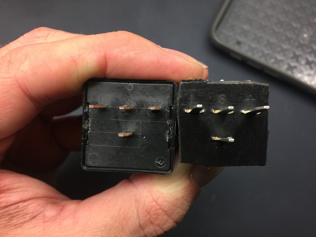
Factory flasher on the left, China LED on the right.
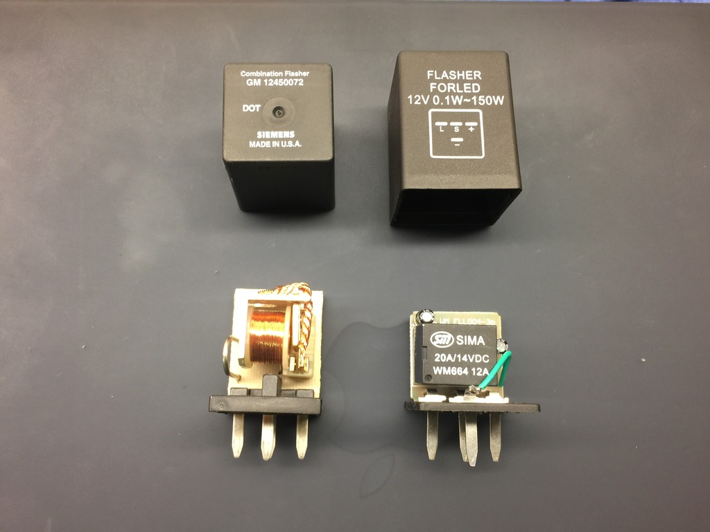
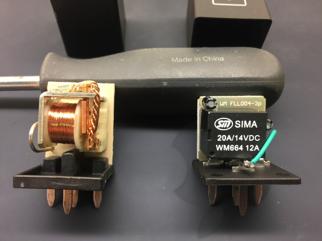
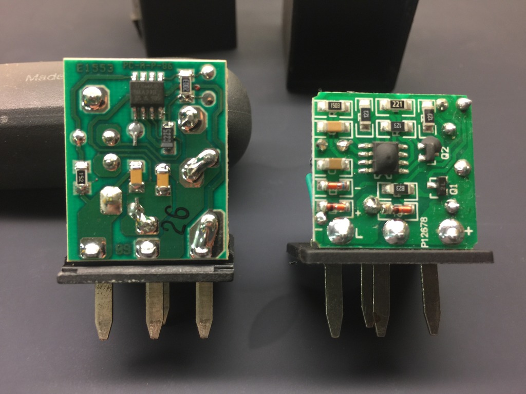
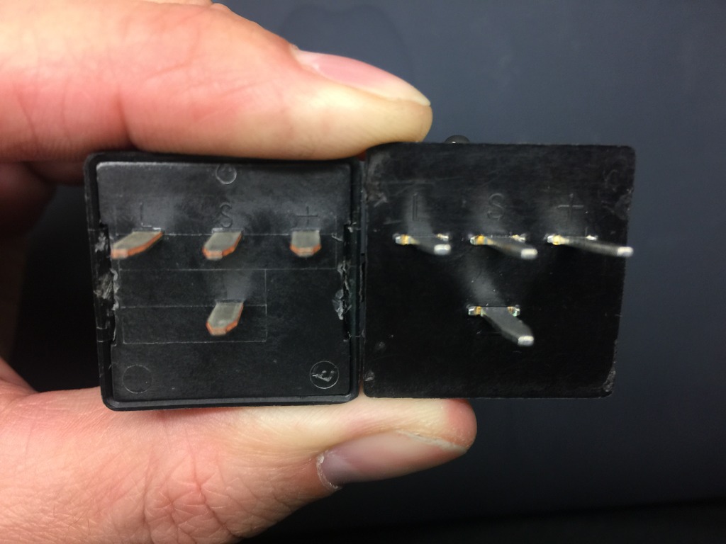
So here's the problem with a more universal Chinese flasher. It works correctly, but doesn't fit. It's impossible to press into place. If you look closely, you can see how the pins are spaced correctly, but are offset in a way that doesn't allow the flasher to seat.
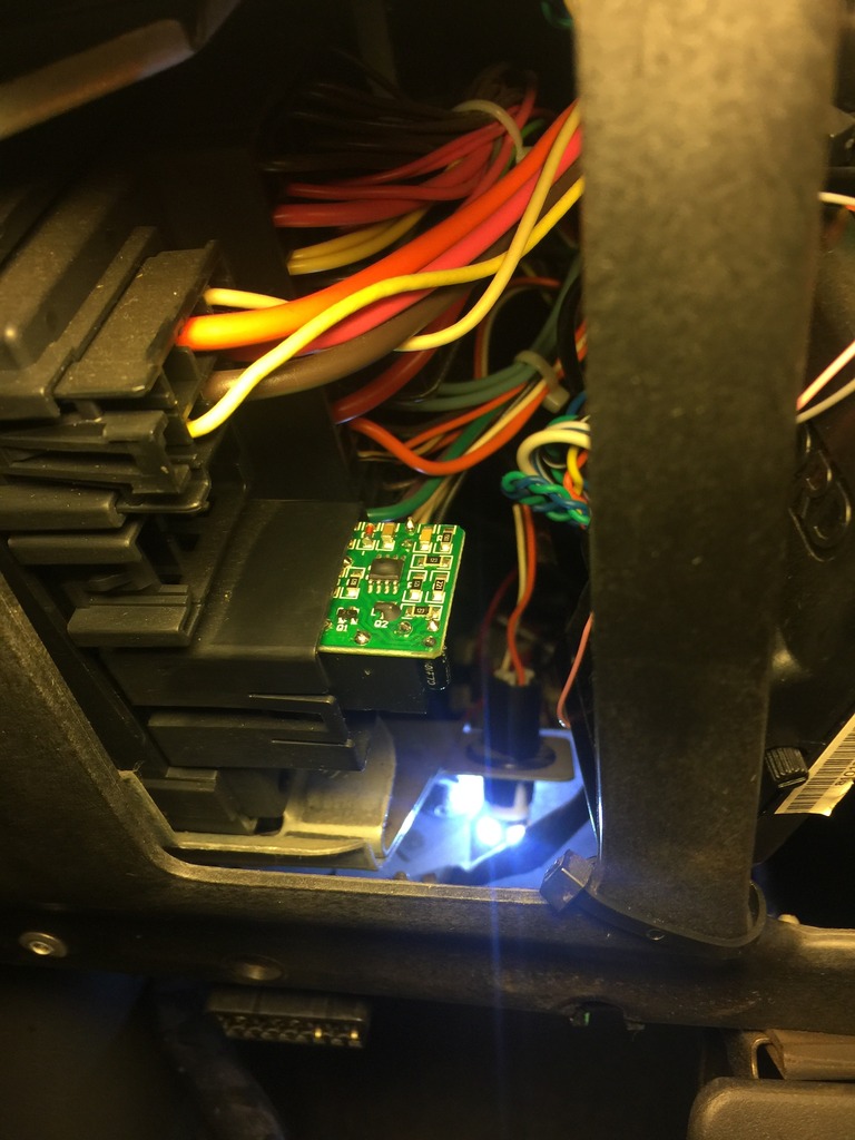
So I reluctantly trimmed it up so that it'd fit. Of course this means that I can no longer install the cover.
I carefully installed it in place. I think it'll be fine exposed like this.
Now, there are 2 was to deal with the blink rate. Load resistors or LED flasher. At first I ordered the resistors, but in the end, that's not the best way to do it.
I had considered modifying the factory flasher. I even found the wiring diagram. My thought was I could install a potentiometer and adjust the flash rate to whatever I wanted. Instead I just ordered an LED flasher from China.
Factory flasher on the left, China LED on the right.


So here's the problem with a more universal Chinese flasher. It works correctly, but doesn't fit. It's impossible to press into place. If you look closely, you can see how the pins are spaced correctly, but are offset in a way that doesn't allow the flasher to seat.

So I reluctantly trimmed it up so that it'd fit. Of course this means that I can no longer install the cover.

I carefully installed it in place. I think it'll be fine exposed like this.
 Jun 21, 2016 | 03:10 AM
#503
Alright, back to the roll pan.
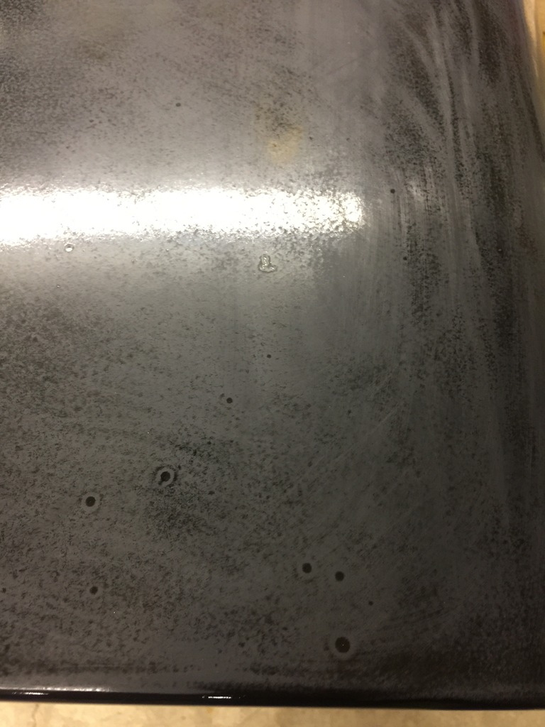
I wet sanded it with 1500 grit sandpaper. There are several fish eyes in the paint. I did my best to avoid it and I'm honestly not certain what caused them. They're so deep that if I were to sand them out, I'd need to repaint. I don't have anymore materials, so I've decided to compromise.
On to the cutting and buffing. Here's the setup I used.
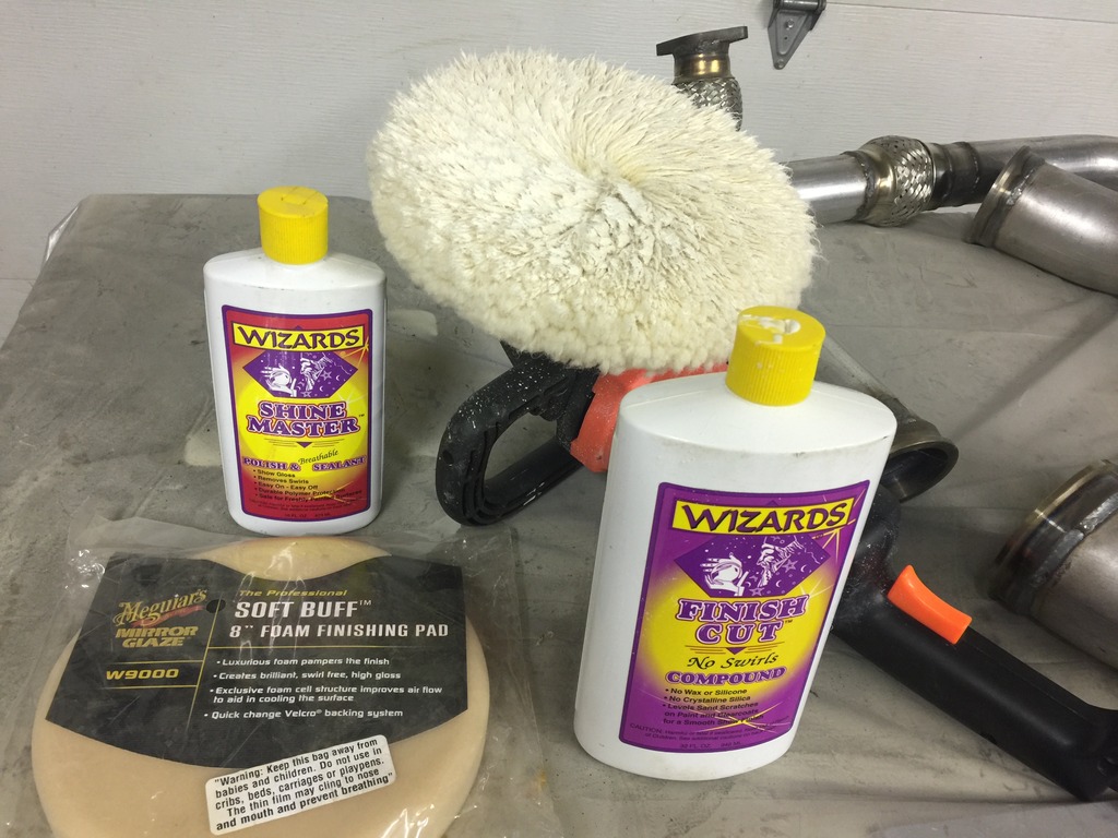
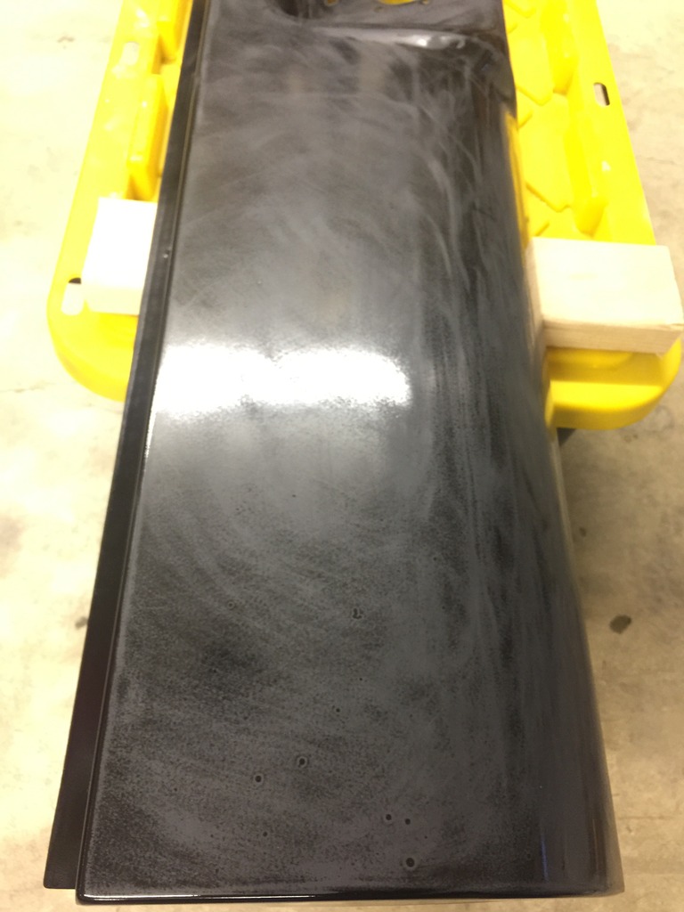
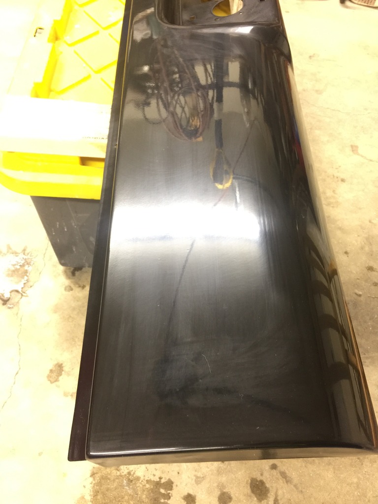
And here are the results after the first go around with the wool pad and cutting compound.
And the second go around.
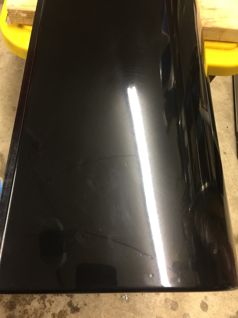
It's super hard to photograph this well. Especially late at night in a garage. Once I get the pan installed, I'll take pics to show how well it matches. Here's what I ended up with though.
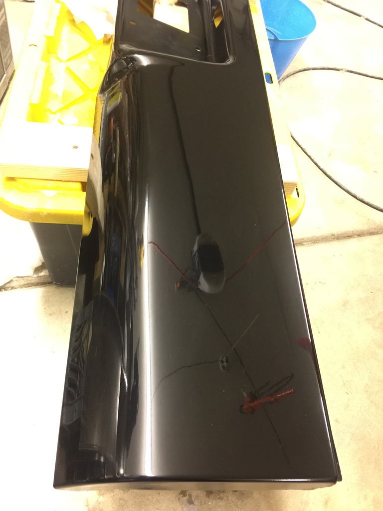
The fish eyes in the paint are a total bummer but other than that, I've got to say I'm impressed. Pretty phenomenal outcome for rattle cans.
At some point I need to weld in my tailgate from when I flipped the handle. At that point I'll paint the entire tailgate. I had considered ordering more of the rattle cans, but nah. This'll give me an opportunity to compare the two. The rattle can setup is far from perfect, but it's certainly good enough for now. Hopefully I can get the roll pan reinstalled tomorrow.
I wet sanded it with 1500 grit sandpaper. There are several fish eyes in the paint. I did my best to avoid it and I'm honestly not certain what caused them. They're so deep that if I were to sand them out, I'd need to repaint. I don't have anymore materials, so I've decided to compromise.


On to the cutting and buffing. Here's the setup I used.

And here are the results after the first go around with the wool pad and cutting compound.

And the second go around.

It's super hard to photograph this well. Especially late at night in a garage. Once I get the pan installed, I'll take pics to show how well it matches. Here's what I ended up with though.


The fish eyes in the paint are a total bummer but other than that, I've got to say I'm impressed. Pretty phenomenal outcome for rattle cans.
At some point I need to weld in my tailgate from when I flipped the handle. At that point I'll paint the entire tailgate. I had considered ordering more of the rattle cans, but nah. This'll give me an opportunity to compare the two. The rattle can setup is far from perfect, but it's certainly good enough for now. Hopefully I can get the roll pan reinstalled tomorrow.


 Jun 23, 2016 | 04:00 AM
#506
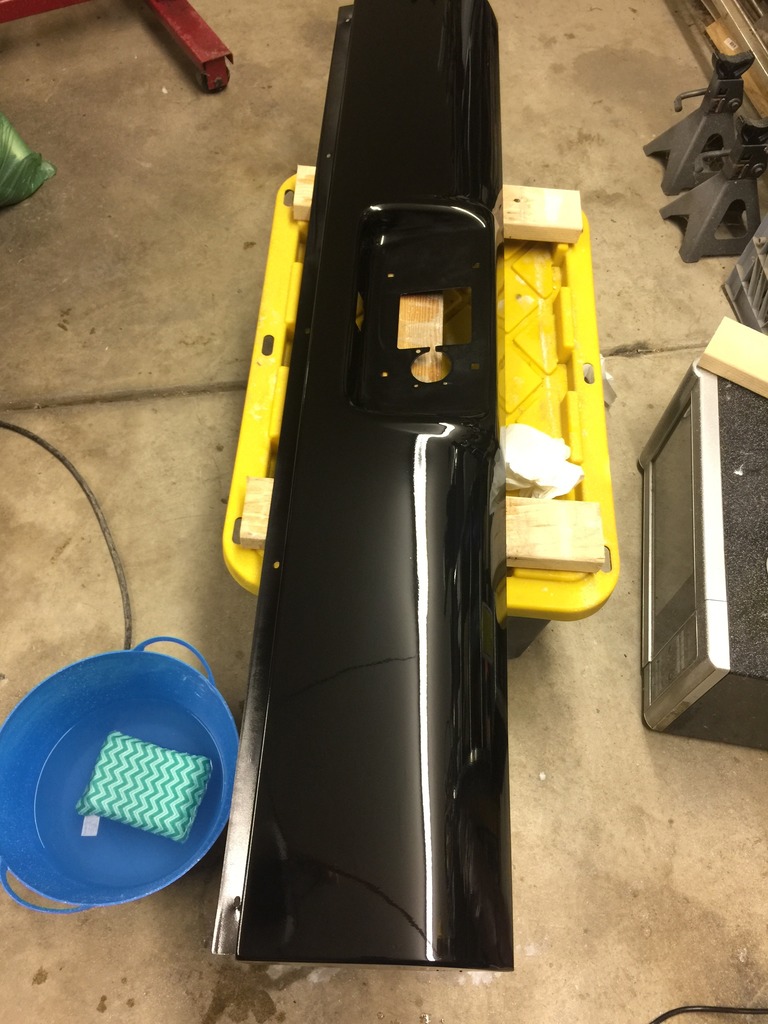
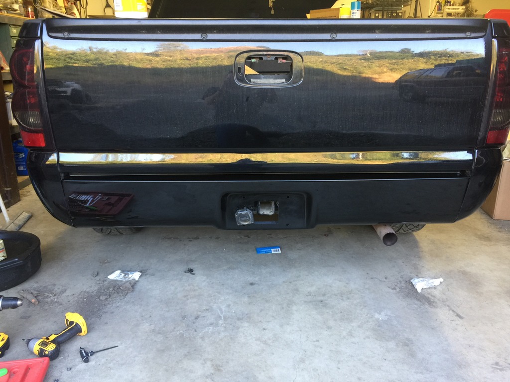
First off, here's a pic with the roll pan in place.
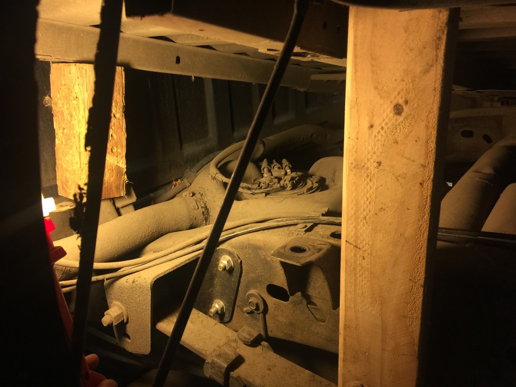
Next up, is installing the Walbro 400 fuel pump. That means, I have to drop the tank or remove the bed. I went with the tilting bed method.
It's covered elsewhere but here's the gist. There are 8 bolts that hold the bed to the frame and 2 bolts that hold the filler neck to the bed. Remove the 4 bolts on the driver's side completely and loosen the 4 bolts on the passengers side. Next, jack or lift the bed up until you can get to the fuel pump. I braced it in 3 different areas with 2x4s and 4x4s.
Once I safely braced the bed in place. I loosened all the dirt surrounding the fuel bucket with my fingers and a screw driver. Then I vacuumed up what I could with a shopvac.
The easiest way for me to get the fuel lines off was to use vacuum hose pliers from harbor freight.
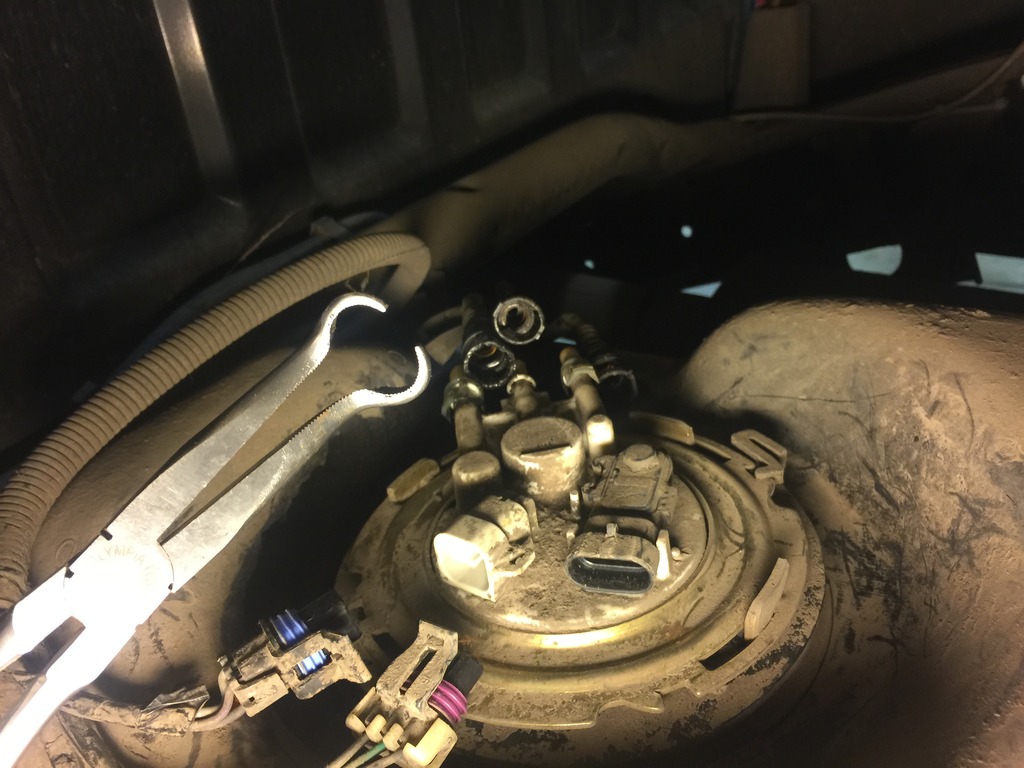
After that, I tapped the locking ring and slowly pulled the bucket out.
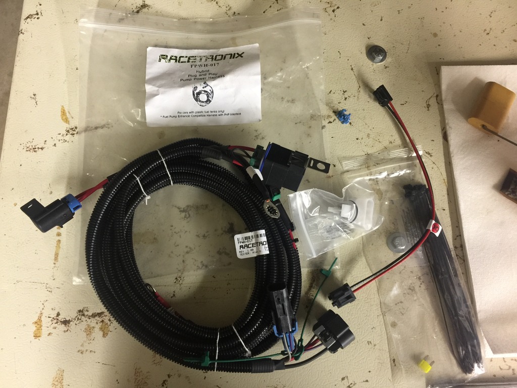
Here's my hotwire kit.
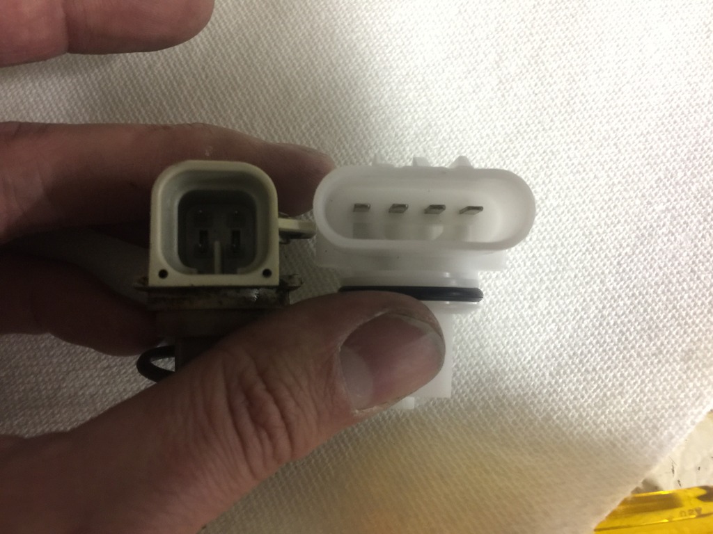
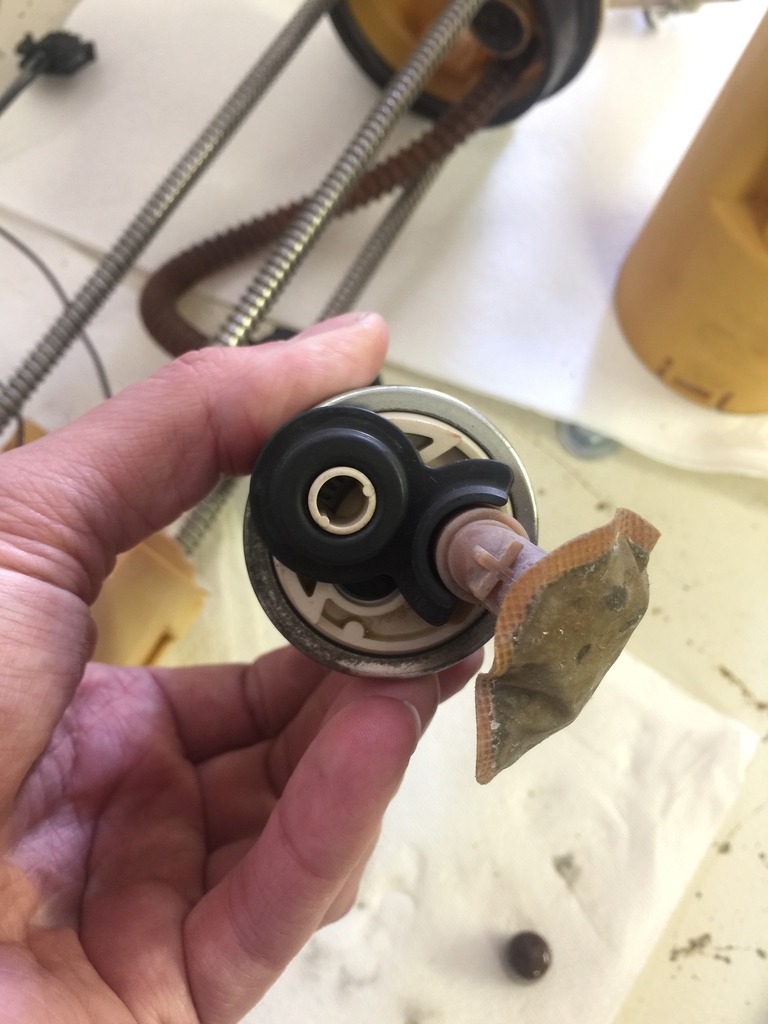
I started disassembling the fuel bucket. I have the earliest style fuel system with a return and the older plug style. Luckily my kit came with the upgraded piece. Removing the factory piece was more challenging than it needed to be though.
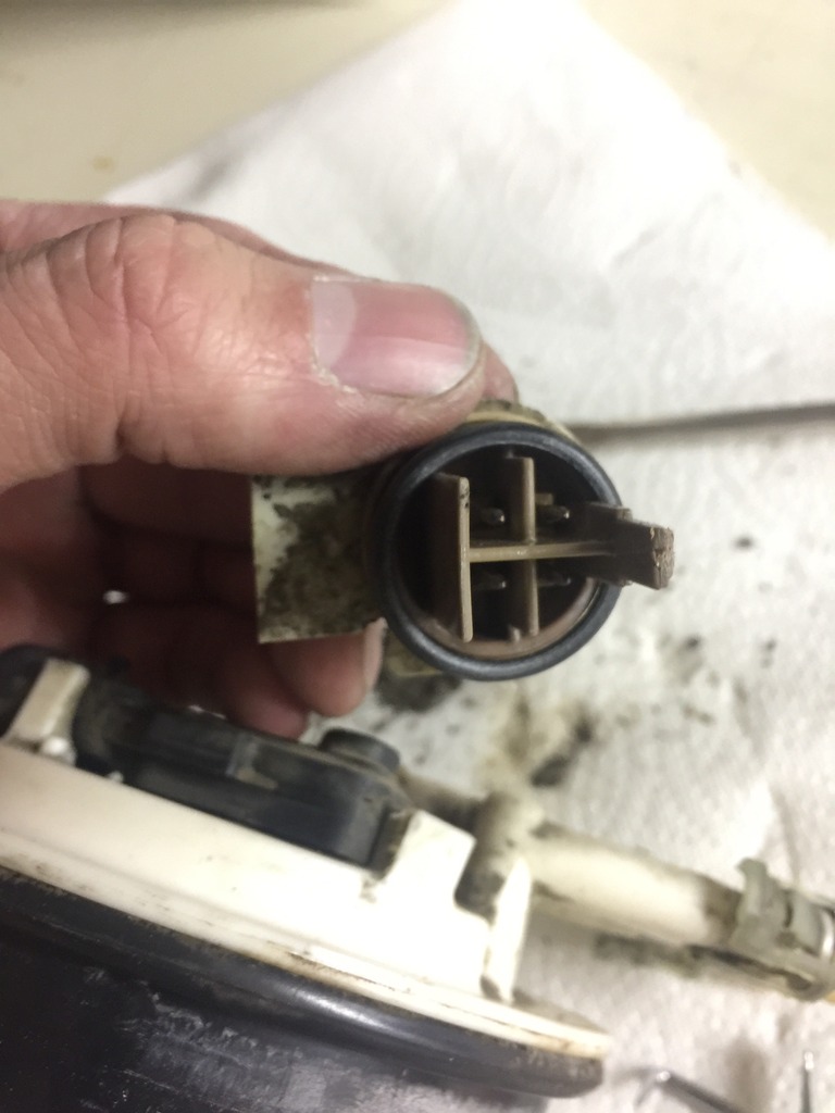
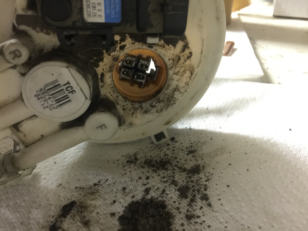
Here's the difference between the two.
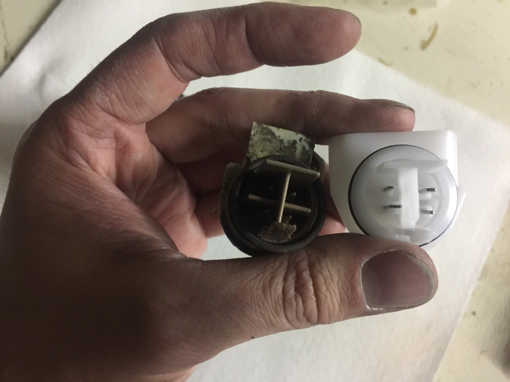
Now, on to the fuel pump. I need some advice here. How should install this?
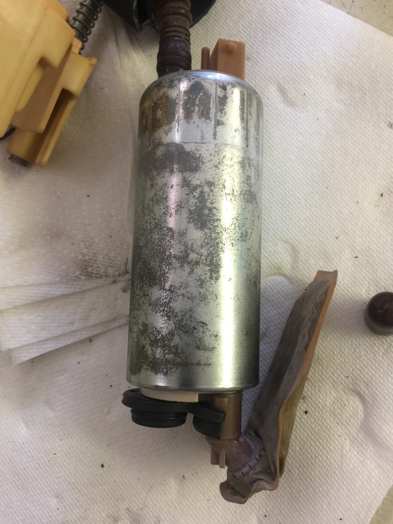
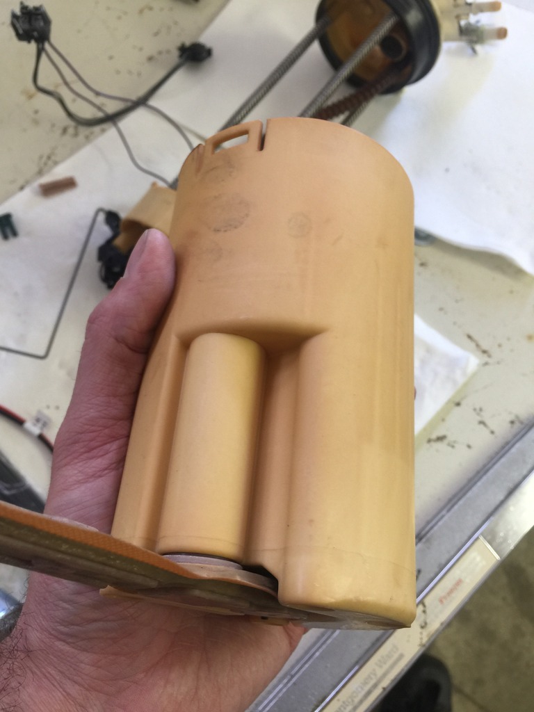
Walbro on the left, factory on the right.
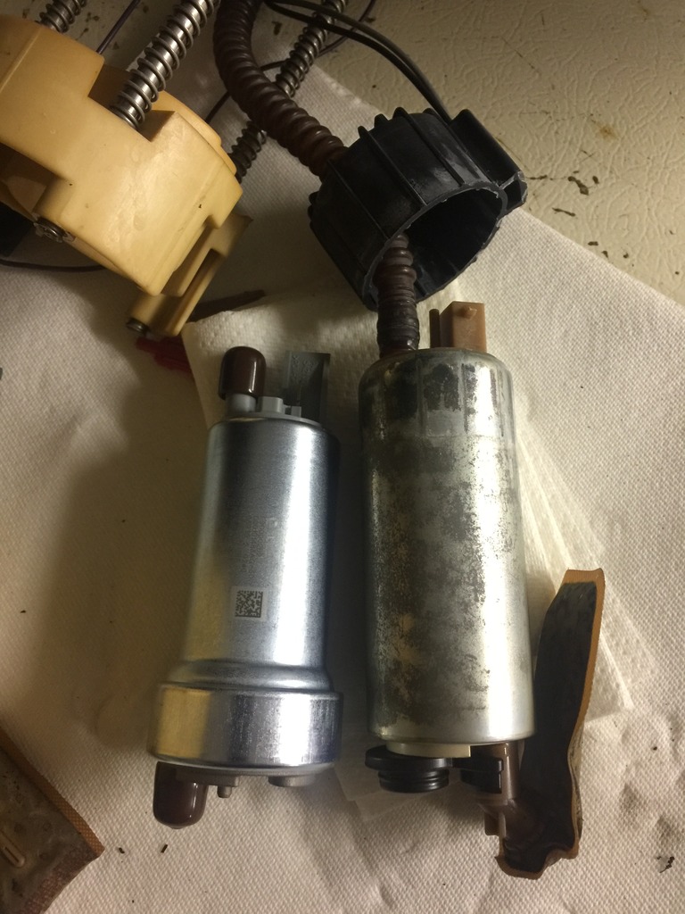
They are so similar in size, that I think I could install the Walbro in place of the factory. I can even fit the factory runner boot on the Walbro pump.
If I were to do that though, I'd trim the rubber piece a little so it fit perfectly.
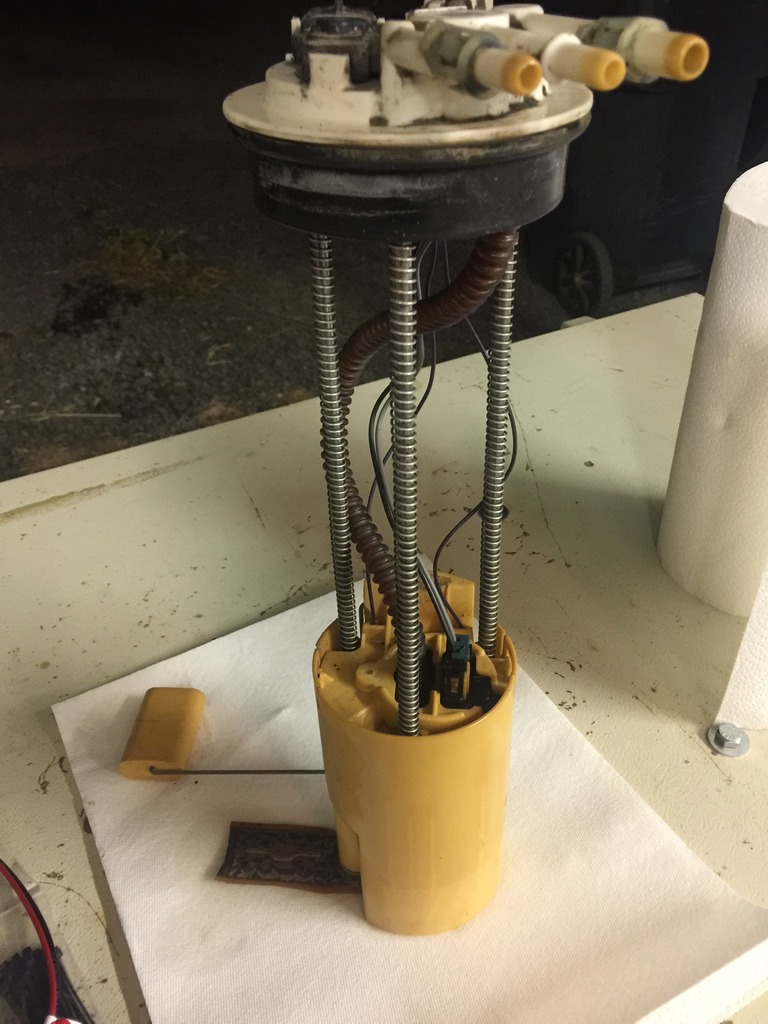
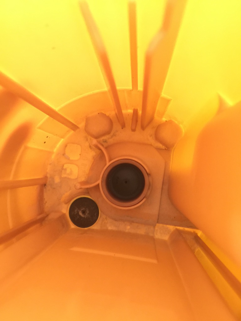
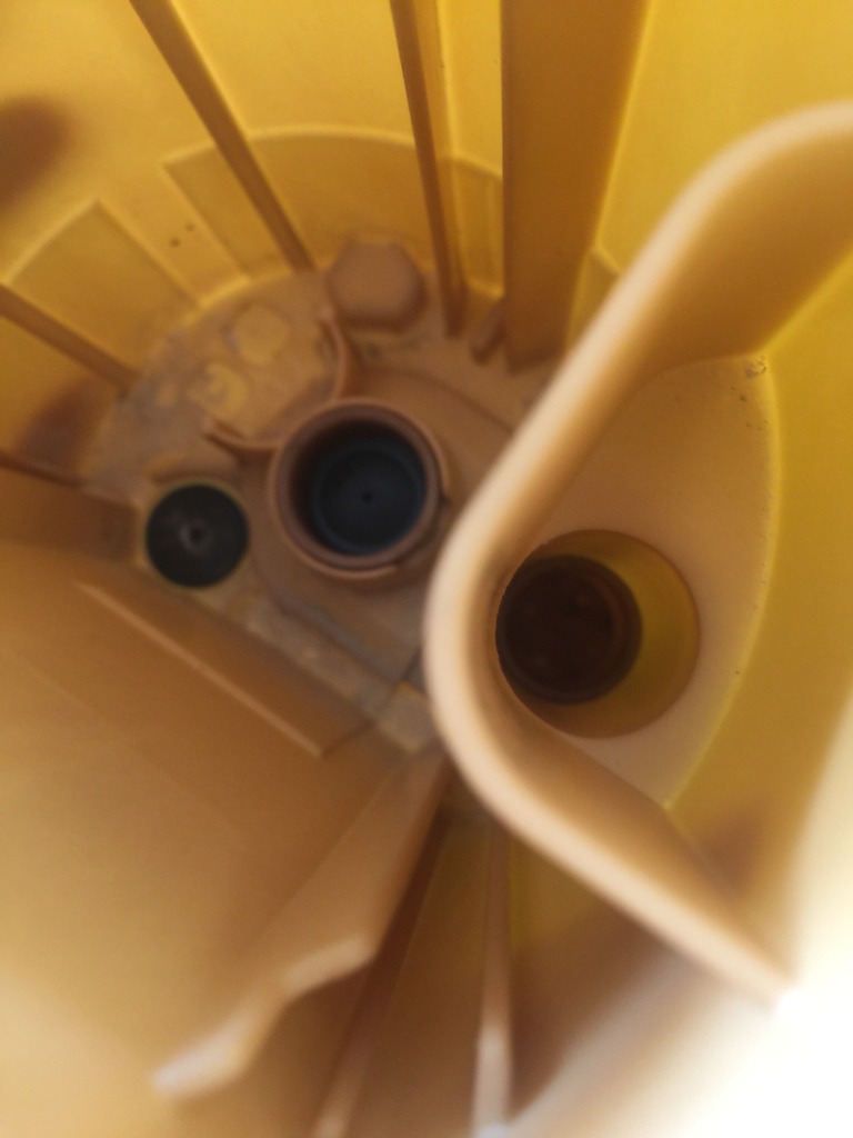
Here's the bucket, it's kinda tiny and odd. The factory fuel pump appears to draw from 2 different places. Seems strange to me.
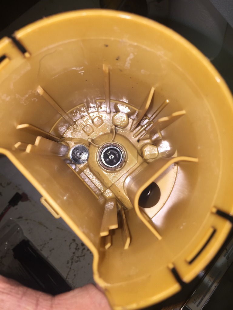
That black rubber piece looks like it's a one way diaphragm.
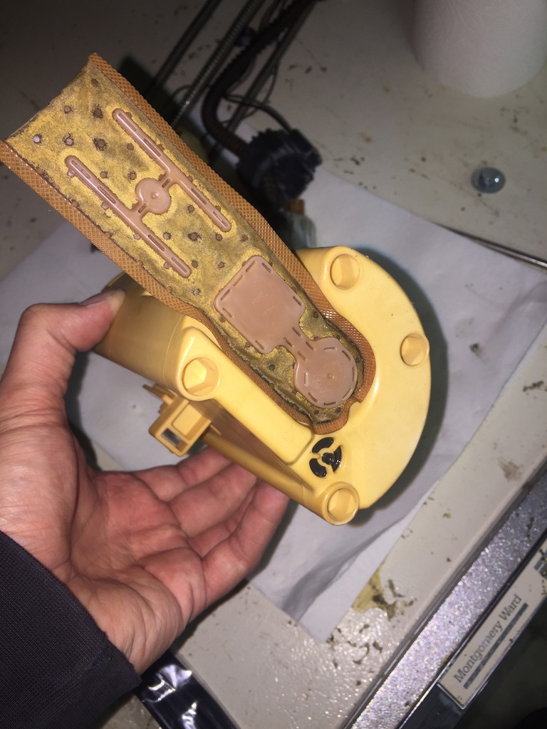
So, what do I do? Gut it? Cut the bottom of the bucket out and install the sock that came with the Walbro pump? Should I instead attempt to install it in a way that's similar to factory utilizing the rubber piece and factory sock? I'm all ears because I really don't know the best way to go about this.
I know the better solution is to swap in an 04-07 fuel tank. I may end up going that route, but if possible, I'd like to work with what I currently have.

Next up, is installing the Walbro 400 fuel pump. That means, I have to drop the tank or remove the bed. I went with the tilting bed method.
It's covered elsewhere but here's the gist. There are 8 bolts that hold the bed to the frame and 2 bolts that hold the filler neck to the bed. Remove the 4 bolts on the driver's side completely and loosen the 4 bolts on the passengers side. Next, jack or lift the bed up until you can get to the fuel pump. I braced it in 3 different areas with 2x4s and 4x4s.

Once I safely braced the bed in place. I loosened all the dirt surrounding the fuel bucket with my fingers and a screw driver. Then I vacuumed up what I could with a shopvac.

The easiest way for me to get the fuel lines off was to use vacuum hose pliers from harbor freight.

After that, I tapped the locking ring and slowly pulled the bucket out.

Here's my hotwire kit.

I started disassembling the fuel bucket. I have the earliest style fuel system with a return and the older plug style. Luckily my kit came with the upgraded piece. Removing the factory piece was more challenging than it needed to be though.


Here's the difference between the two.


Now, on to the fuel pump. I need some advice here. How should install this?
Walbro on the left, factory on the right.

They are so similar in size, that I think I could install the Walbro in place of the factory. I can even fit the factory runner boot on the Walbro pump.

If I were to do that though, I'd trim the rubber piece a little so it fit perfectly.
Here's the bucket, it's kinda tiny and odd. The factory fuel pump appears to draw from 2 different places. Seems strange to me.

That black rubber piece looks like it's a one way diaphragm.

So, what do I do? Gut it? Cut the bottom of the bucket out and install the sock that came with the Walbro pump? Should I instead attempt to install it in a way that's similar to factory utilizing the rubber piece and factory sock? I'm all ears because I really don't know the best way to go about this.
I know the better solution is to swap in an 04-07 fuel tank. I may end up going that route, but if possible, I'd like to work with what I currently have.
Jun 24, 2016 | 05:04 PM
#507
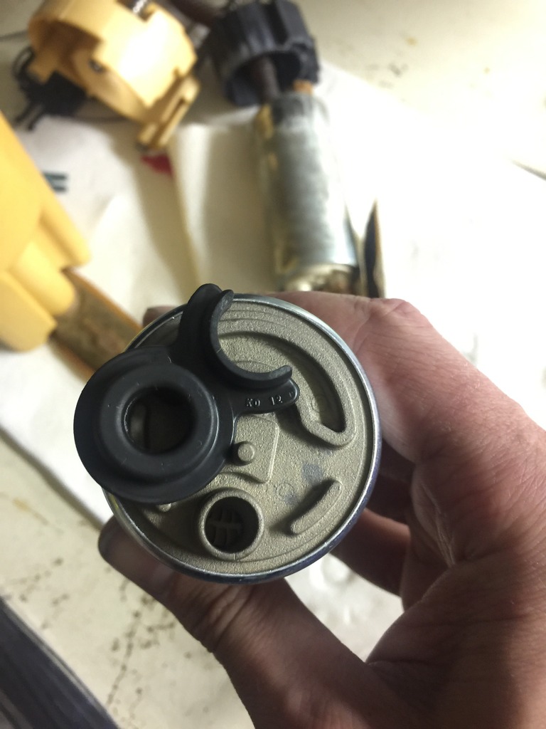
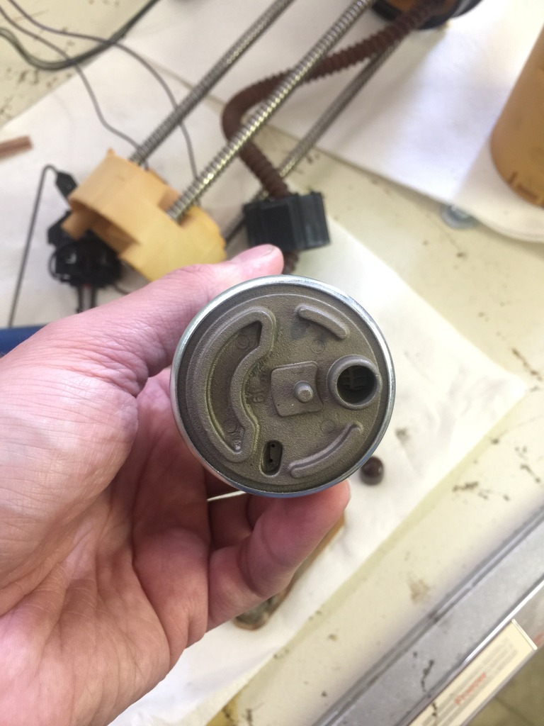
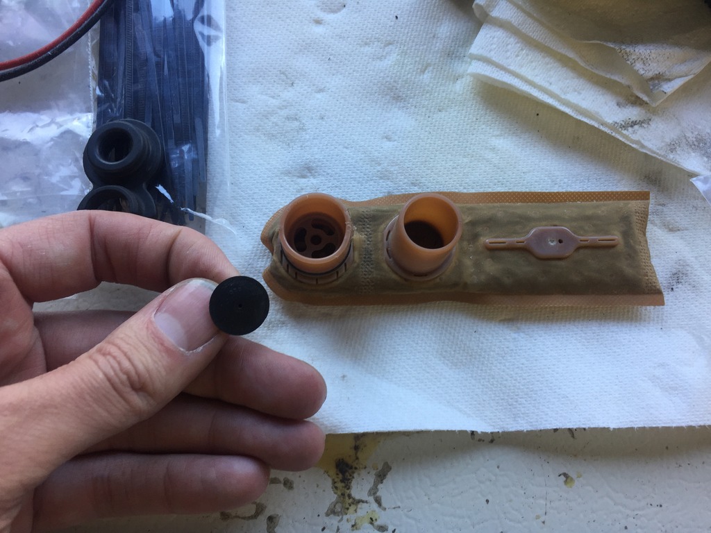
Okay, here's a pic of the bottom side of the factory pump.
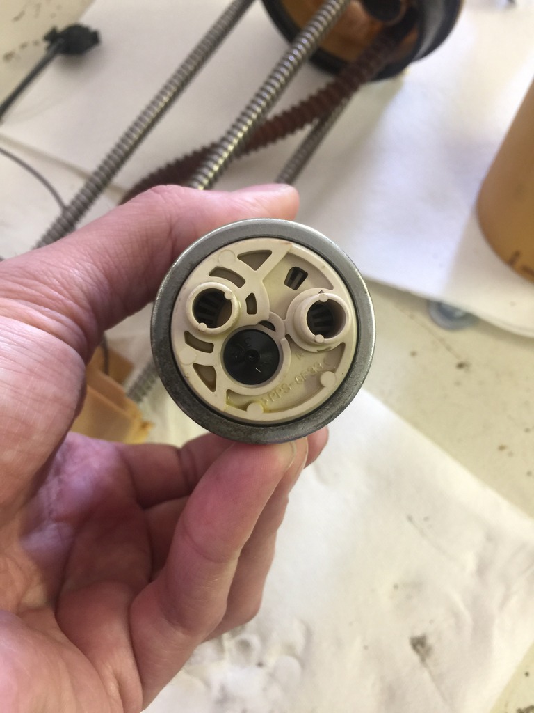
Here's what it looks like with the fittings on.

That black rubber piece fits into the center section. I was mistaken on how it functions. Drilling a hole in the bump in the center simply would be drilling a hole in the bottom.
Along the right side here is a type of reservoir. One thing I could do, is remove this or drill holes in it. This would allow the pump to pull from inside and outside the bucket.
You can see that the factory sock connects in 2 places. One, the reservoir and two the tank.
Walbro pump.
Thoughts?

Here's what it looks like with the fittings on.


That black rubber piece fits into the center section. I was mistaken on how it functions. Drilling a hole in the bump in the center simply would be drilling a hole in the bottom.

Along the right side here is a type of reservoir. One thing I could do, is remove this or drill holes in it. This would allow the pump to pull from inside and outside the bucket.

You can see that the factory sock connects in 2 places. One, the reservoir and two the tank.

Walbro pump.

Thoughts?
Jun 25, 2016 | 11:20 PM
#508
Here's what I decided to do.
Remember this pic?
Well, I took that rubber piece and trimmed it in a way where it'd fit on the Walbro pump.
Next, I placed that pump in the bucket, but first, I removed the one way rubber piece from the factory sock.
Here are my thoughts. The pump will now draw only from the factory sock, which is connected outside the bucket, and inside the bucket. There is a tube that is cast up into the bucket. Essentially this defeats utilizing the bucket as a reservoir but, allows for cooling the pump. The return fills the bucket which will overflow into the sock where the pump draws from. Unless of course the entire assembly is submerged under fuel.
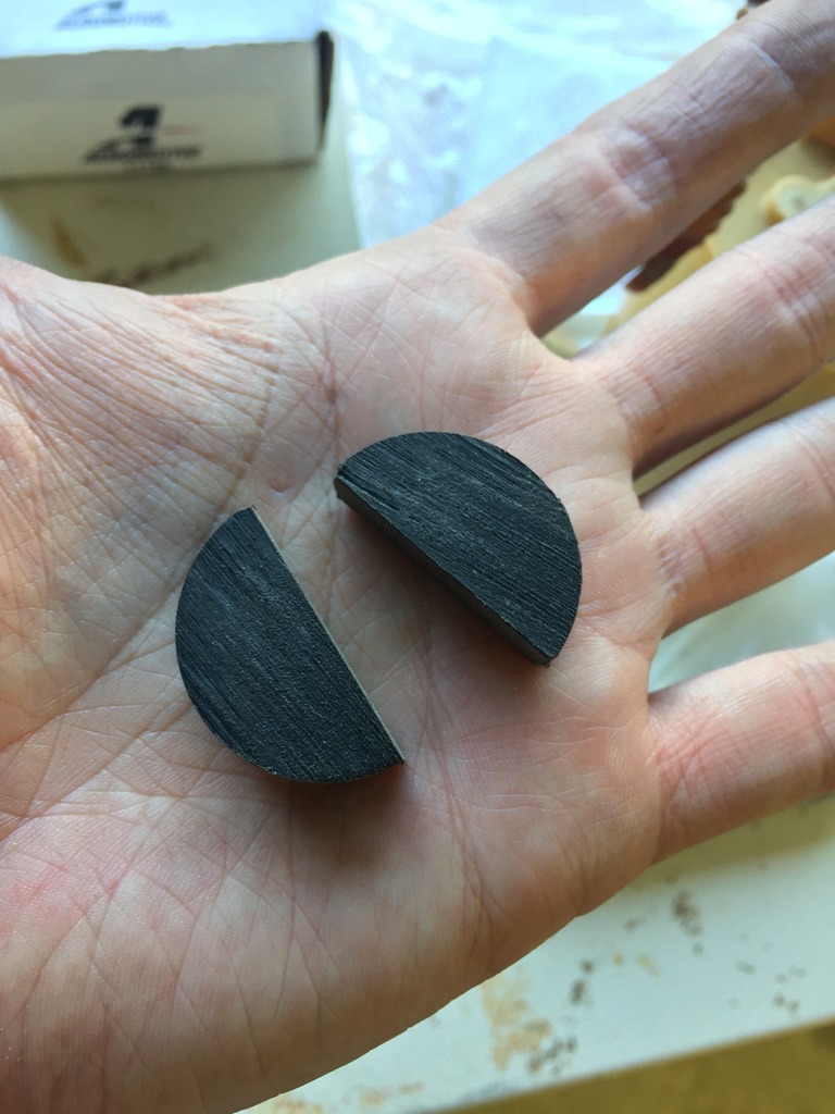
The next issue is the fact that the pump is 0.481 inches shorter than I needed it to be. Remember when I build the stud mount coilover setup? Well, my first thought was to use delrin. After further research I discovered that delrin deforms and doesn't bounce back, a poor choice for suspension, but a good choice for being submerged in fuel.
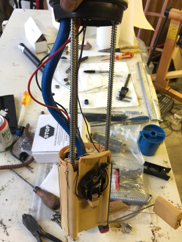
So, I cut out a slice of delrin and then cut it in half. I placed this above the fuel pump which sandwiches it into place.
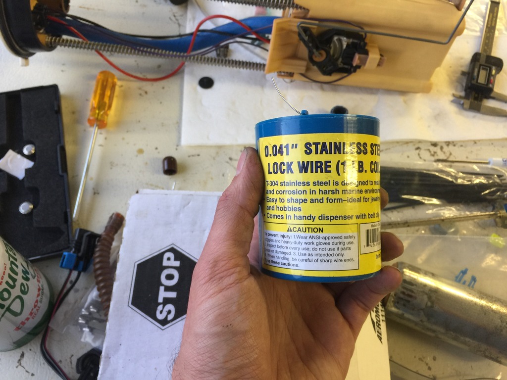
The next issue I faced was securing the pump. It is stuck in there pretty well, but I've also changed the design. The 2 pieces of the bucket weren't designed to hold the pump in place. At first I was planning on using stainless steel zip ties, then I remembered the wire I used for securing my dirt bike grips.
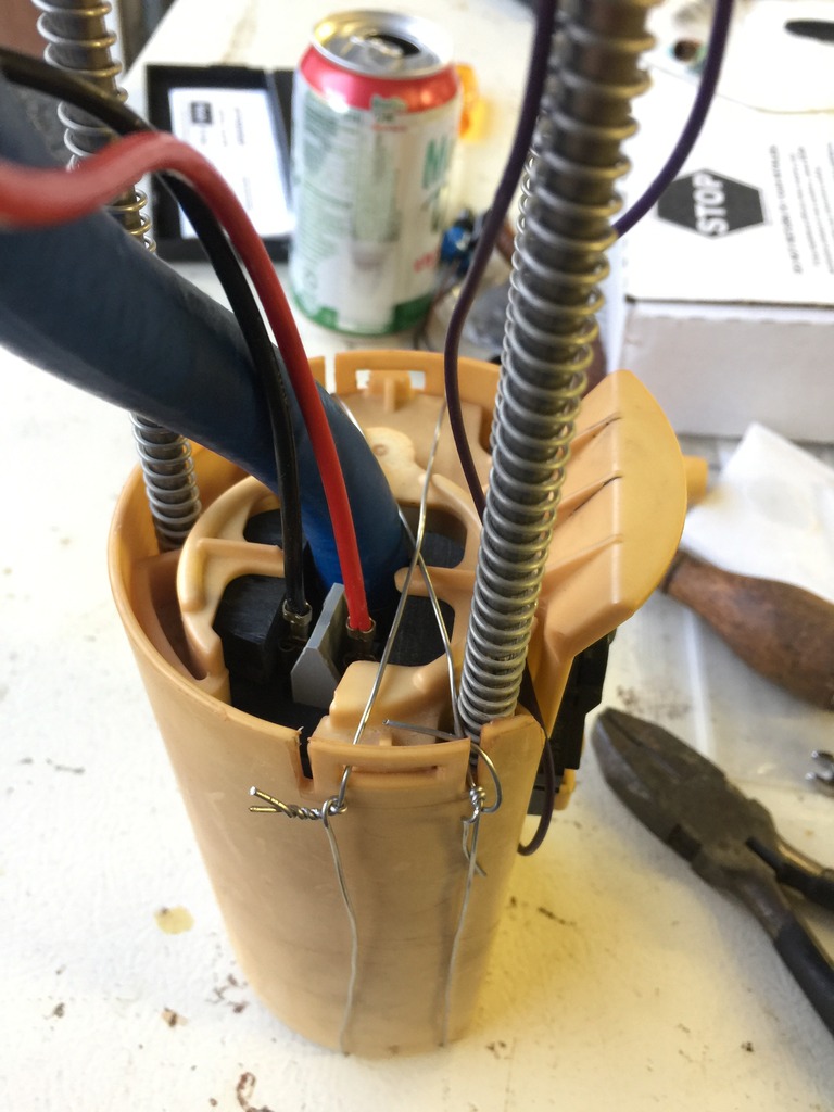
This is something I picked up a while back at Harbor Freight. It claims it'll hold up. Here's hoping!
Now, fitting the submersible fuel line in place to the pump was very straight forward, the top was pretty tight. I ended up using a 1/4" end wrench, one tiny turn at a time.
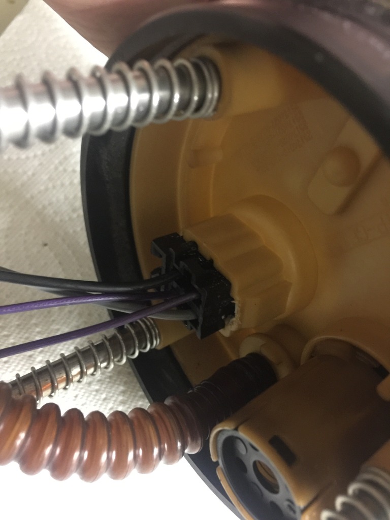
Also seen here is the upgraded and rewired connector.
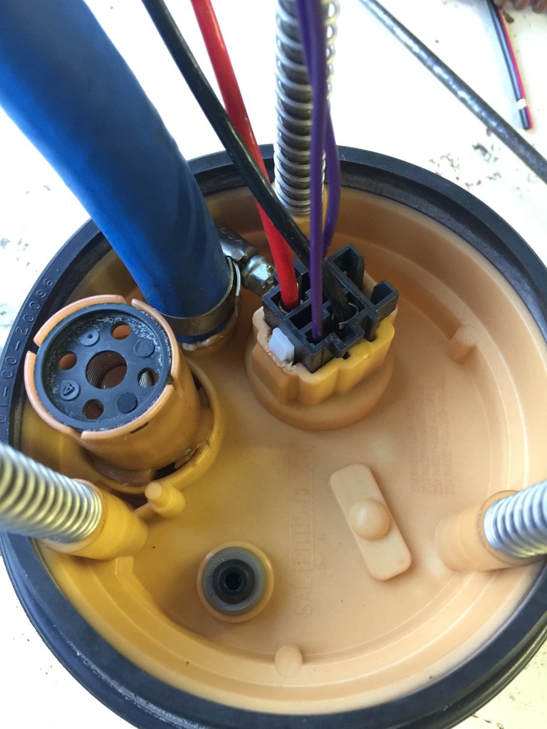
Sorry for the messy workspace. All done.
I'm wondering if I should secure the wires at all? Maybe to the fuel line itself? Also, I had considered soldering the power lines to the pump terminals, but I think they'll hold.
Remember this pic?
Well, I took that rubber piece and trimmed it in a way where it'd fit on the Walbro pump.
Next, I placed that pump in the bucket, but first, I removed the one way rubber piece from the factory sock.

Here are my thoughts. The pump will now draw only from the factory sock, which is connected outside the bucket, and inside the bucket. There is a tube that is cast up into the bucket. Essentially this defeats utilizing the bucket as a reservoir but, allows for cooling the pump. The return fills the bucket which will overflow into the sock where the pump draws from. Unless of course the entire assembly is submerged under fuel.
The next issue is the fact that the pump is 0.481 inches shorter than I needed it to be. Remember when I build the stud mount coilover setup? Well, my first thought was to use delrin. After further research I discovered that delrin deforms and doesn't bounce back, a poor choice for suspension, but a good choice for being submerged in fuel.
So, I cut out a slice of delrin and then cut it in half. I placed this above the fuel pump which sandwiches it into place.

The next issue I faced was securing the pump. It is stuck in there pretty well, but I've also changed the design. The 2 pieces of the bucket weren't designed to hold the pump in place. At first I was planning on using stainless steel zip ties, then I remembered the wire I used for securing my dirt bike grips.

This is something I picked up a while back at Harbor Freight. It claims it'll hold up. Here's hoping!

Now, fitting the submersible fuel line in place to the pump was very straight forward, the top was pretty tight. I ended up using a 1/4" end wrench, one tiny turn at a time.
Also seen here is the upgraded and rewired connector.

Sorry for the messy workspace. All done.

I'm wondering if I should secure the wires at all? Maybe to the fuel line itself? Also, I had considered soldering the power lines to the pump terminals, but I think they'll hold.
Jun 27, 2016 | 03:52 AM
#509
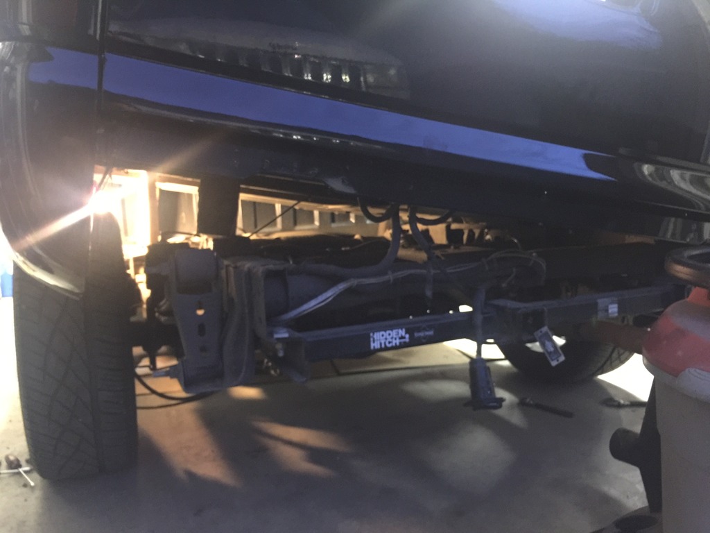
Installed the Hotwire kit. I ran the line along the frame rail on the driver's side. I highlighted in blue how the wire is ran. It goes to a fuse and then directly to the alternator.
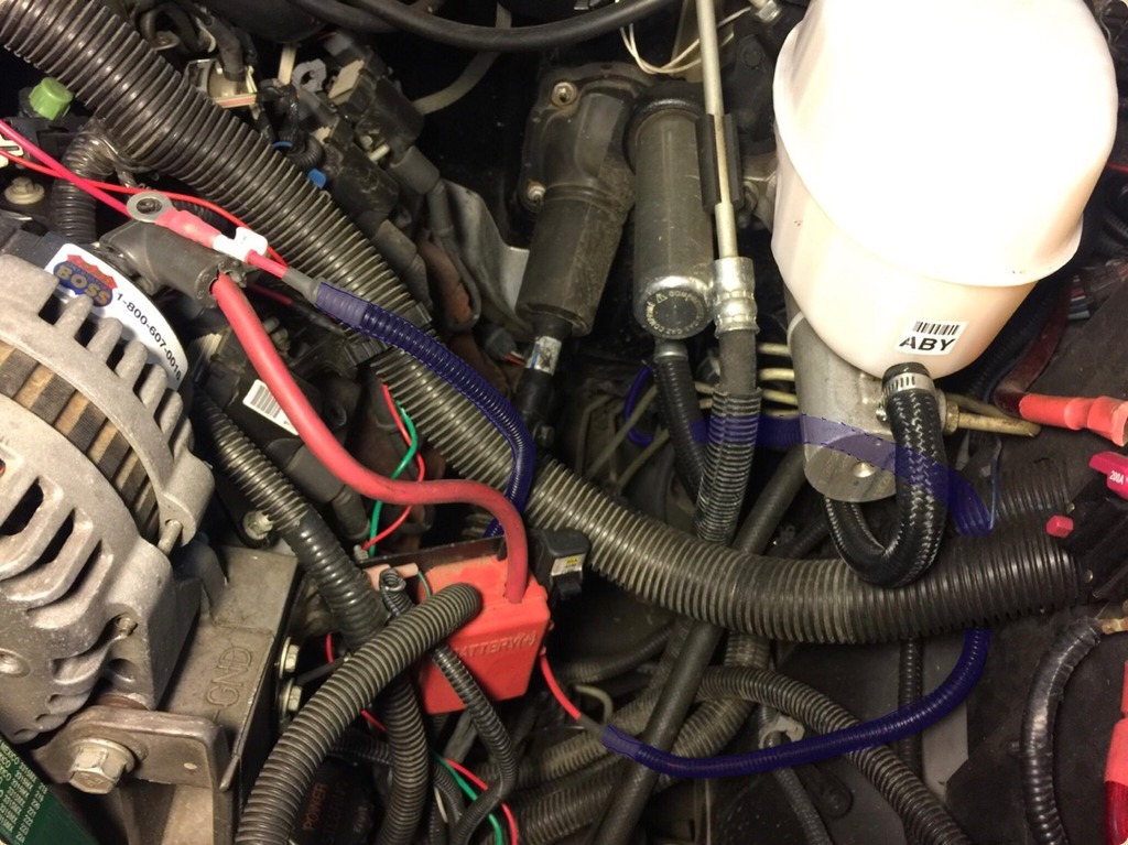
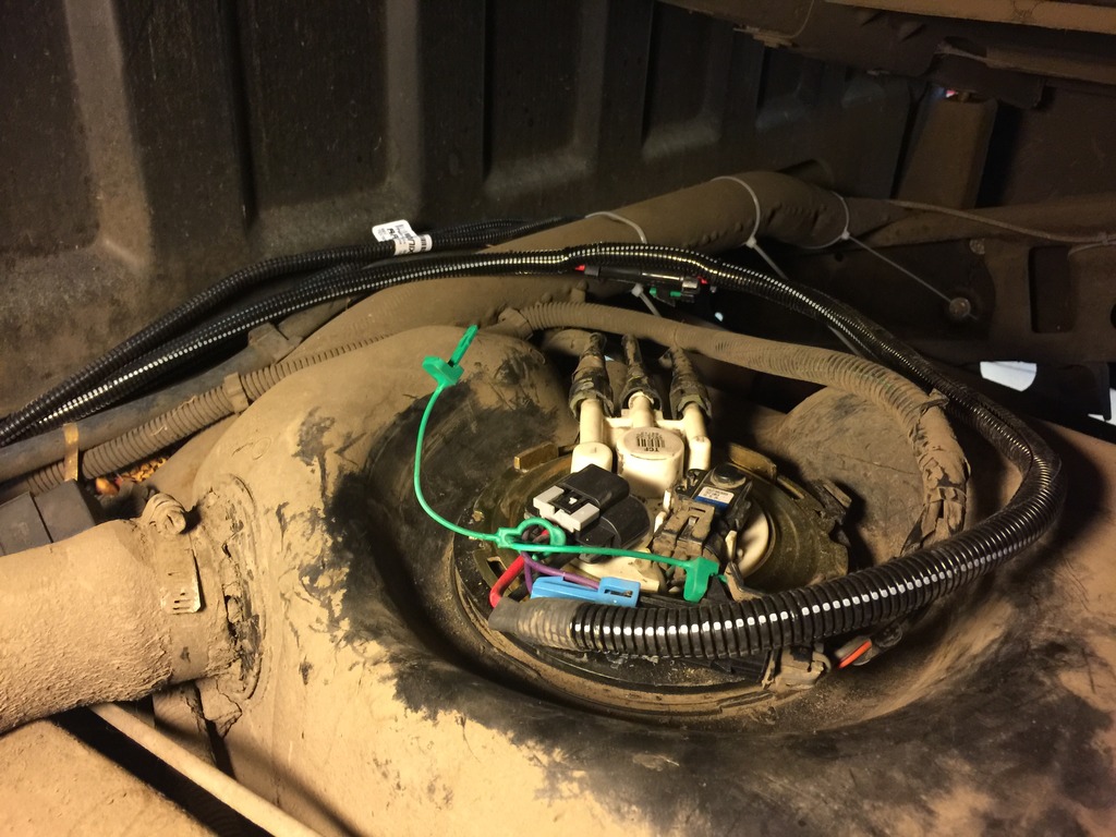
Right here you can see where there is a factory ground point. This is on the driver's side right behind the cab. The factory loom and the fuel fill hose is grounded at this point. I decided to ground the fuel pump wiring kit here as well. To get the harness to reach, I had to remove a factory bracket, install the wiring kit's ground underneath and reinstall the bracket.
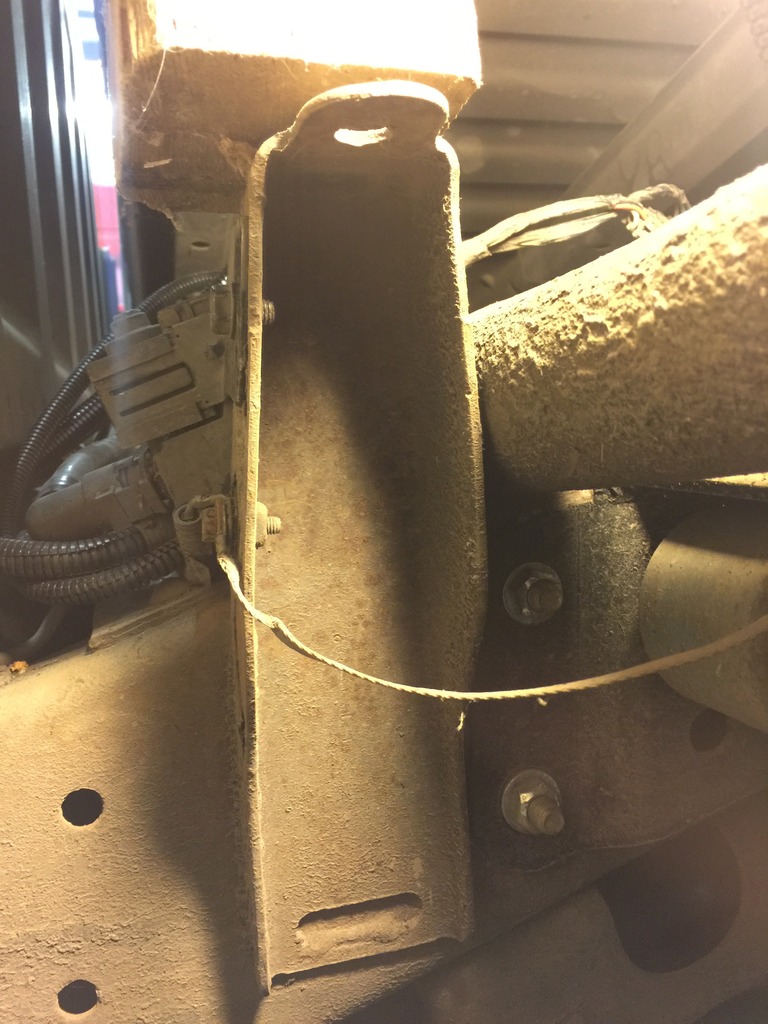
From a different angle. You can see in the center near the fill hose the hotwire kit's relay laying down.
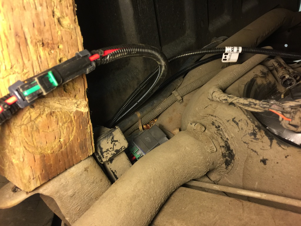
I had so much extra wire that I ran it across to the other side and back. That's what the 3 zip ties are doing. I'll trim them up when I get the wiring exactly where I want it and put everything back together.
When I installed the fuel pressure gauge in March, this was my fuel pressure:
50-58ish
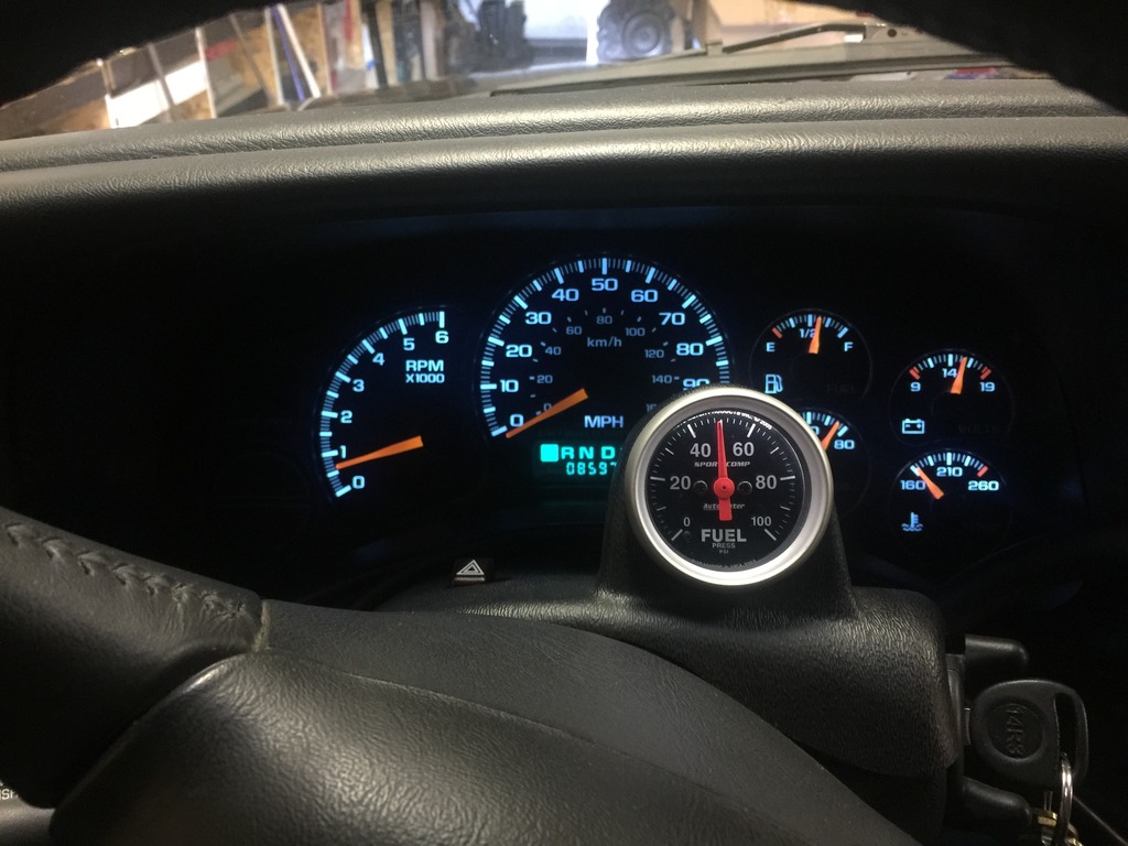
Before I put everything back together I started the truck up to test everything out. It started right up. I let it idle for a few minutes. Here is my current fuel pressure:
72ish
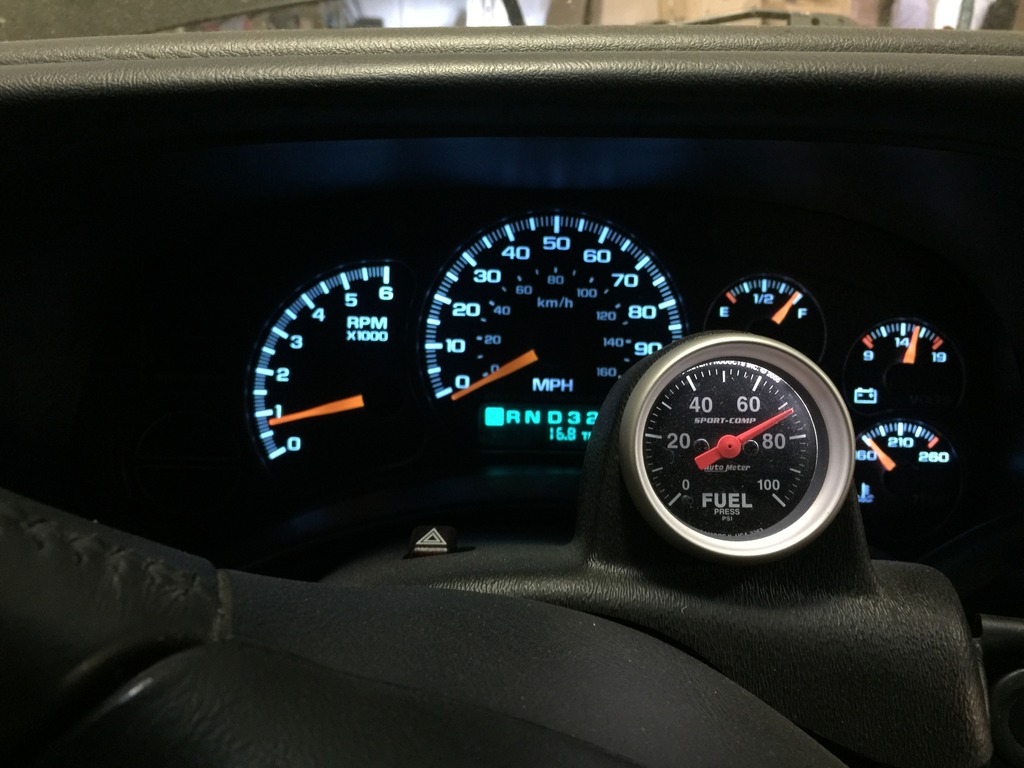
Okay, so is this an indication of my fuel pressure regulator failing to keep up with the Walbro pump? If so, what's next? Either ebay fuel rails and an external fuel pressure regulator. Or, I need to figure out how to bypass the factory regulator. To my surprise, finding a billet plug/cap is much harder than I thought it'd be. I was hoping that there may be an aftermarket FPR that is vacuum referenced and adjustable, that'd fit in the fuel rail.
Also, I tested the regulator by pulling the vacuum line off and on several times. The fuel pressure didn't change much, but I'm wondering this: Do you guys think maybe a factory replacement regulator would maybe keep up?
The reason I ask, is because I ended up pulling off the vacuum line to show my step father and fuel came out. This indicates failure to me. I wonder if the regulator was weak and the pump caused failure or something along those lines? I have read that the factory FPR Will hold up to the Walbro 400. It's one of the reasons I went with it over the 450.

Right here you can see where there is a factory ground point. This is on the driver's side right behind the cab. The factory loom and the fuel fill hose is grounded at this point. I decided to ground the fuel pump wiring kit here as well. To get the harness to reach, I had to remove a factory bracket, install the wiring kit's ground underneath and reinstall the bracket.

From a different angle. You can see in the center near the fill hose the hotwire kit's relay laying down.

I had so much extra wire that I ran it across to the other side and back. That's what the 3 zip ties are doing. I'll trim them up when I get the wiring exactly where I want it and put everything back together.

When I installed the fuel pressure gauge in March, this was my fuel pressure:
50-58ish

Before I put everything back together I started the truck up to test everything out. It started right up. I let it idle for a few minutes. Here is my current fuel pressure:
72ish

Okay, so is this an indication of my fuel pressure regulator failing to keep up with the Walbro pump? If so, what's next? Either ebay fuel rails and an external fuel pressure regulator. Or, I need to figure out how to bypass the factory regulator. To my surprise, finding a billet plug/cap is much harder than I thought it'd be. I was hoping that there may be an aftermarket FPR that is vacuum referenced and adjustable, that'd fit in the fuel rail.
Also, I tested the regulator by pulling the vacuum line off and on several times. The fuel pressure didn't change much, but I'm wondering this: Do you guys think maybe a factory replacement regulator would maybe keep up?
The reason I ask, is because I ended up pulling off the vacuum line to show my step father and fuel came out. This indicates failure to me. I wonder if the regulator was weak and the pump caused failure or something along those lines? I have read that the factory FPR Will hold up to the Walbro 400. It's one of the reasons I went with it over the 450.
Jun 27, 2016 | 05:45 AM
#510

I can't really answer your question related to the FPR, but on my '03 Silverado I installed a 450 and it seems to do just fine. I was suspecting a tired fuel pump so I replaced the pump with a Walbro 450 about 9 mos ago and it's been fine...
Just my $0.02
Just my $0.02