

{Project} White Noise- 2005 ECSB 2wd Silverado, Forged 402/4l80e/PTE 88mm turbo
 Apr 23, 2014 | 09:05 PM
#61

Alright, fuel lines and plumbing is 100% done.
-10an filter came last week.
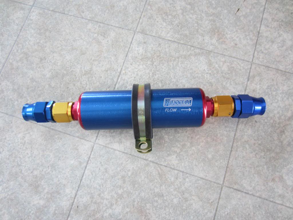
Filter mounted and feed line ran.
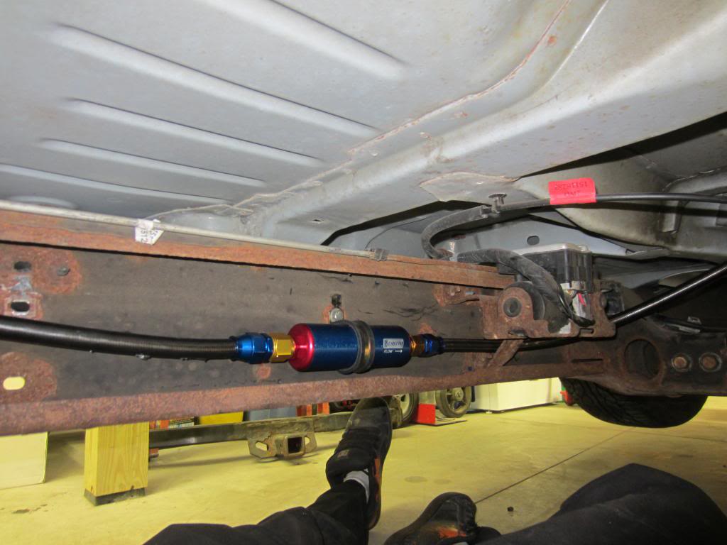
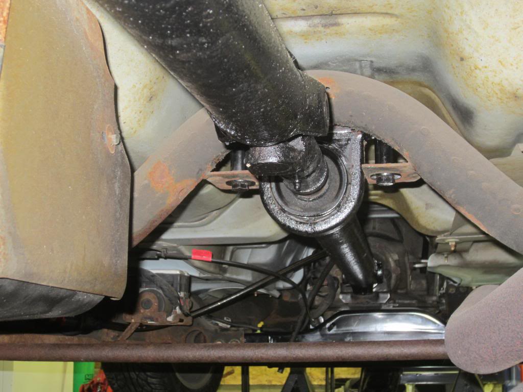
My stock driveshaft fits with the 4l80e. I have around 1/2" of slip from trans to axle at the resting height. Should be good.
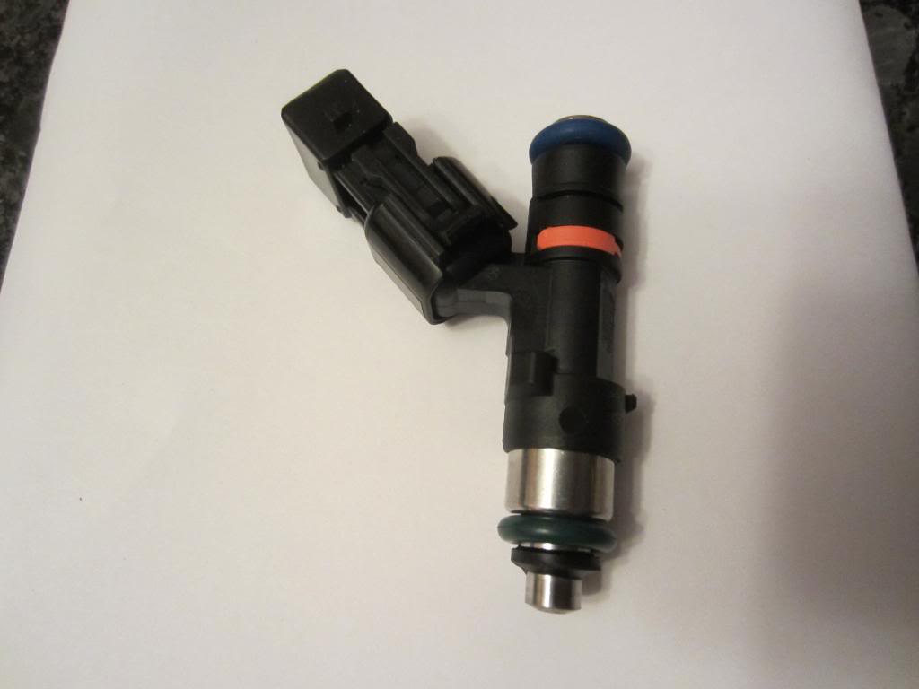
Also got my FIC 1000CCs
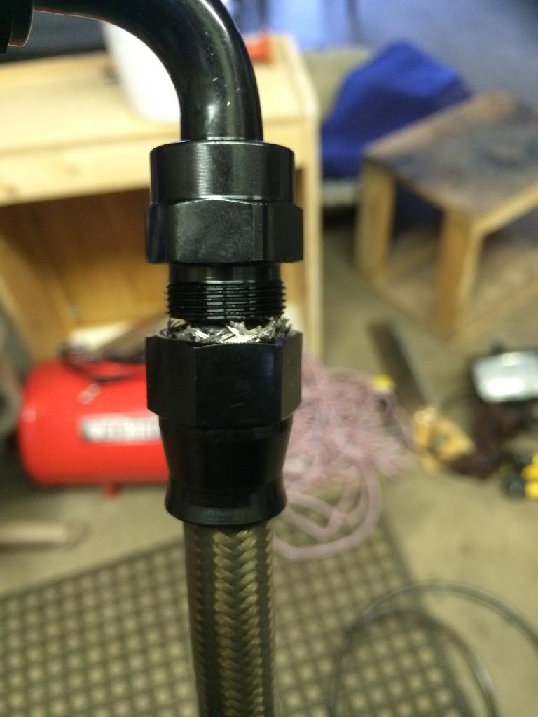
Some pics I took while making the return line. It's a pain to terminate the PTFE lines until you figure out just the right trick. I can now do it without having to trim back any of the stainless.
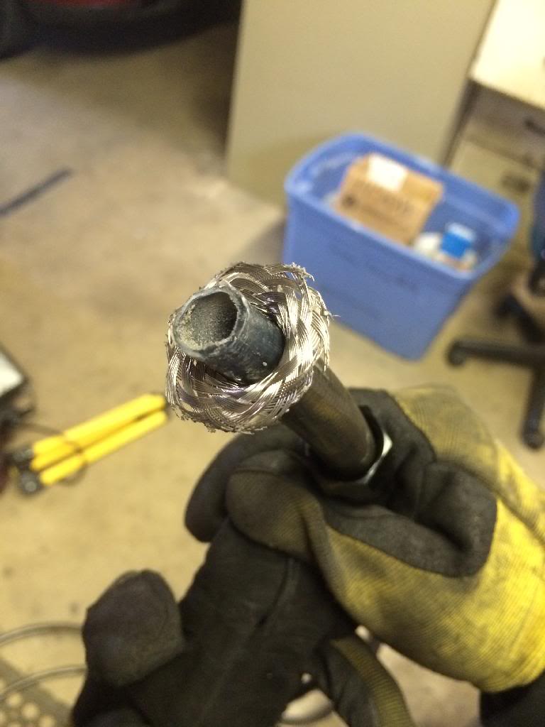
Once I get to this point, use a small screwdriver to push the stainless down and away from the threads.
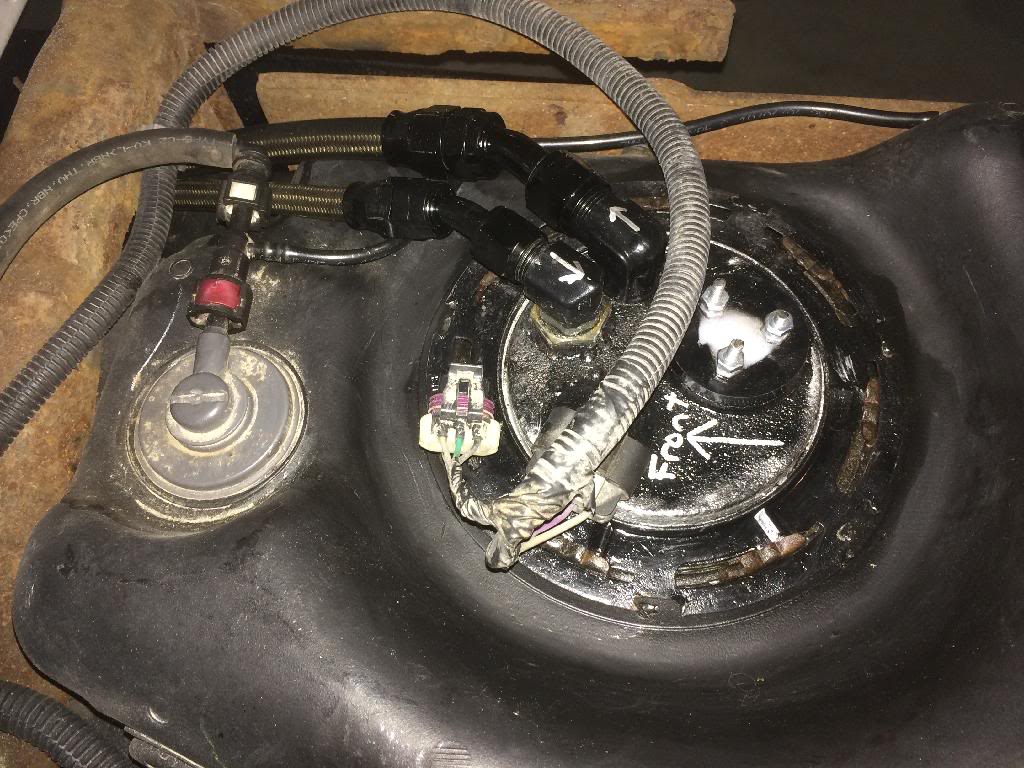
The exit angles from the pump fit just perfect.
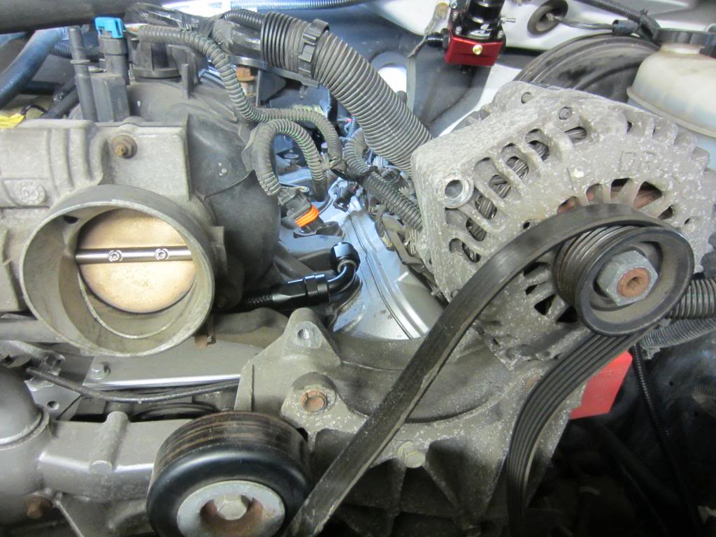
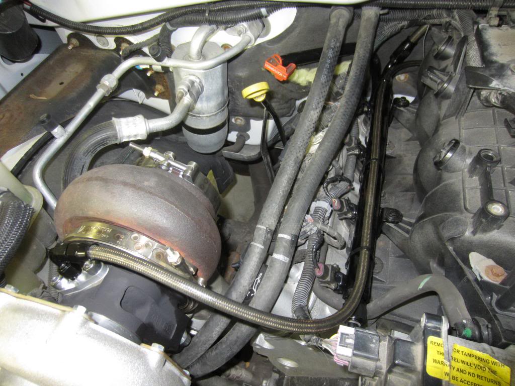
Installing the injectors and fuel rails. I have to pull my alternator up to be able to fit the injectors into the manifold since the front elbow on the rail is in such close clearance with the alternator. (Pictured some posts back)
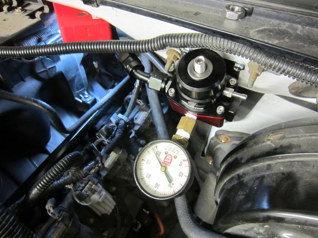
Here's the regulator mounted and plumbed. I've read on here about mounting the regulator to the firewall and track rules. I have several friends that have theirs set up this way and have never had a problem or even a mention of it being a problem at the track so i went this way because it's really the best and easiest location.
I put a temporary gauge in to to pressure test the system and check for leaks. I had a leak at the back of the rail on my feed fitting, the flare end, not the hose connection. Ended up having to take that off and back on a few times to get it seated just right. Besides that, it was good!
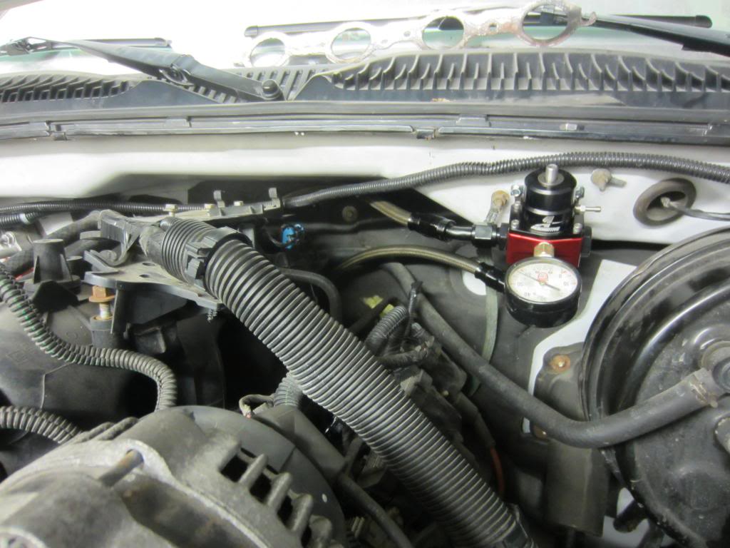
Held and flowed at 58psi just fine.
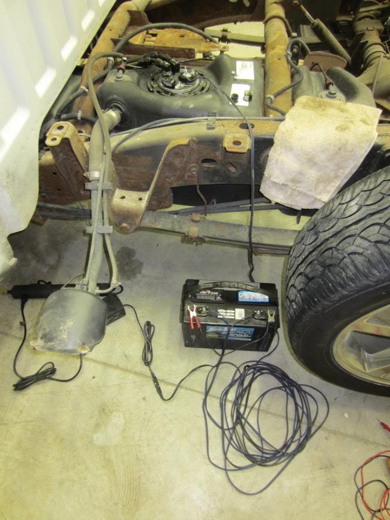
Here's the pump setup for testing.
-10an filter came last week.

Filter mounted and feed line ran.

My stock driveshaft fits with the 4l80e. I have around 1/2" of slip from trans to axle at the resting height. Should be good.

Also got my FIC 1000CCs

Some pics I took while making the return line. It's a pain to terminate the PTFE lines until you figure out just the right trick. I can now do it without having to trim back any of the stainless.

Once I get to this point, use a small screwdriver to push the stainless down and away from the threads.

The exit angles from the pump fit just perfect.

Installing the injectors and fuel rails. I have to pull my alternator up to be able to fit the injectors into the manifold since the front elbow on the rail is in such close clearance with the alternator. (Pictured some posts back)

Here's the regulator mounted and plumbed. I've read on here about mounting the regulator to the firewall and track rules. I have several friends that have theirs set up this way and have never had a problem or even a mention of it being a problem at the track so i went this way because it's really the best and easiest location.
I put a temporary gauge in to to pressure test the system and check for leaks. I had a leak at the back of the rail on my feed fitting, the flare end, not the hose connection. Ended up having to take that off and back on a few times to get it seated just right. Besides that, it was good!

Held and flowed at 58psi just fine.

Here's the pump setup for testing.
 Apr 23, 2014 | 09:10 PM
#62
Next on the list is making the turbo feed line and hot side exhaust. All those parts are on order.
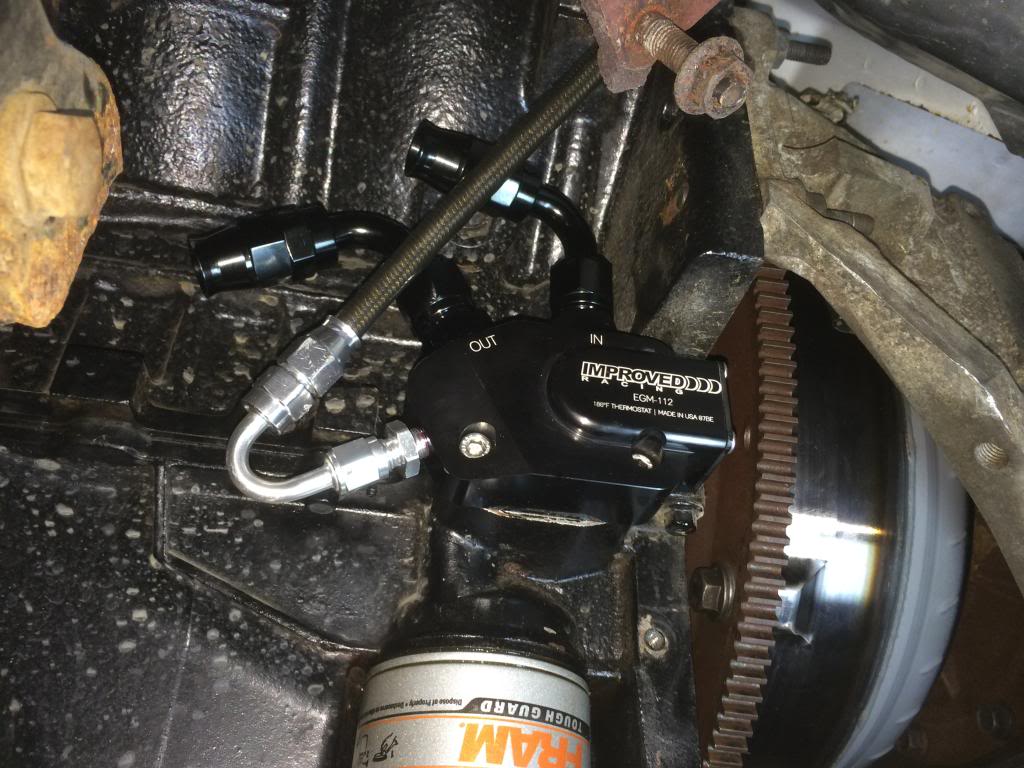
This is the oil cooler I ordered today. Thermostat opens at 180* to allow flow to the cooler. Click the image for link to the site.

This is the oil cooler I ordered today. Thermostat opens at 180* to allow flow to the cooler. Click the image for link to the site.
Apr 23, 2014 | 11:10 PM
#63

The thermostat is built in or are you using an external one? Where did you find that?


 May 7, 2014 | 08:18 AM
#67
It's been a while since a good update.
I've got the oil cooler block installed and the turbo line run from it. -4an has beent he most difficult to terminate yet. Good thing I only have the one line to do.
Then I've been waiting on a few parts so I did some little busy work. I've bveen wanting to do the grille mesh black so I did that finally.
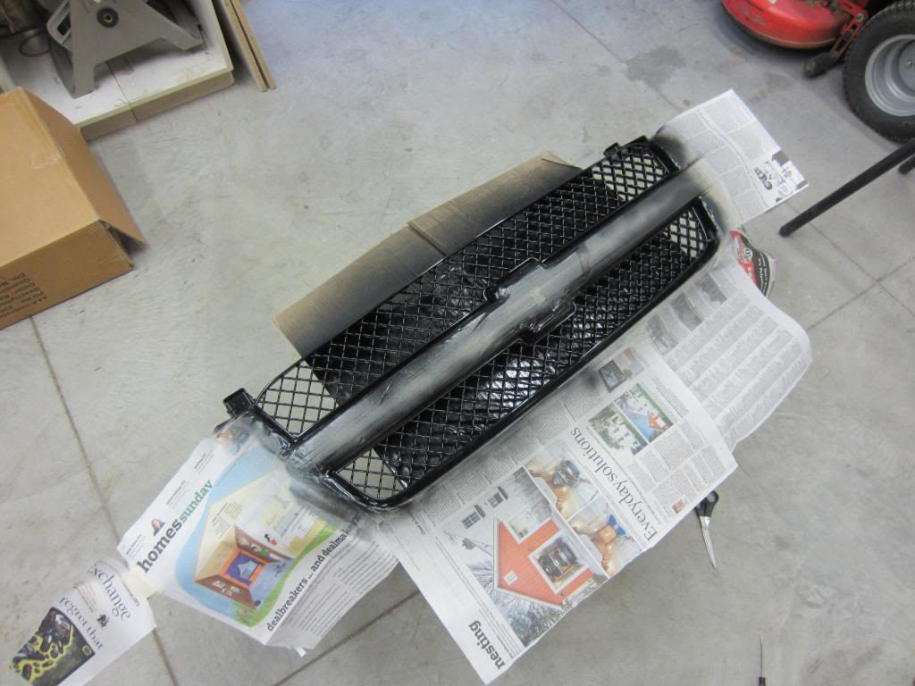
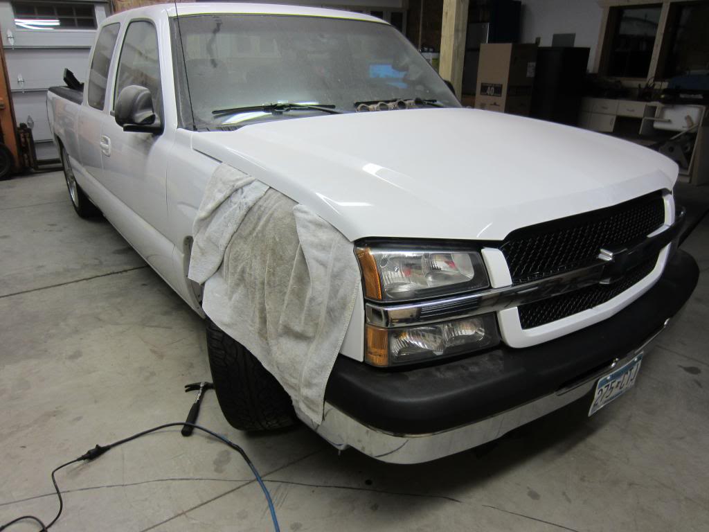 I have to touch up some of the white.
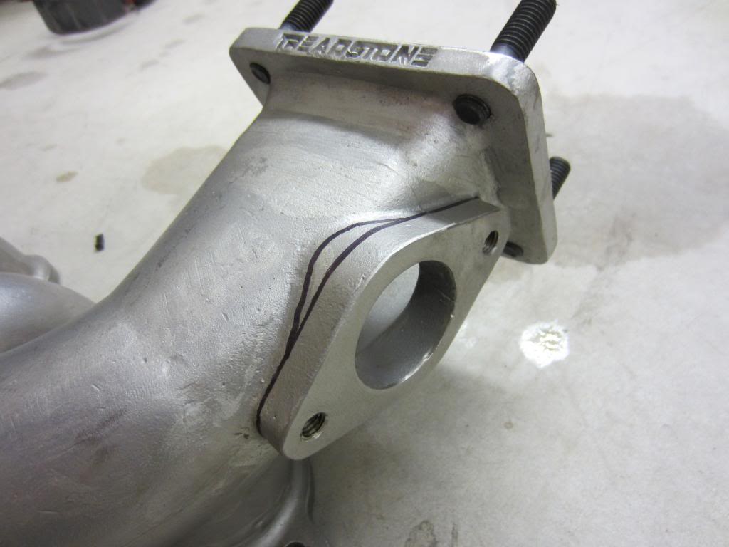
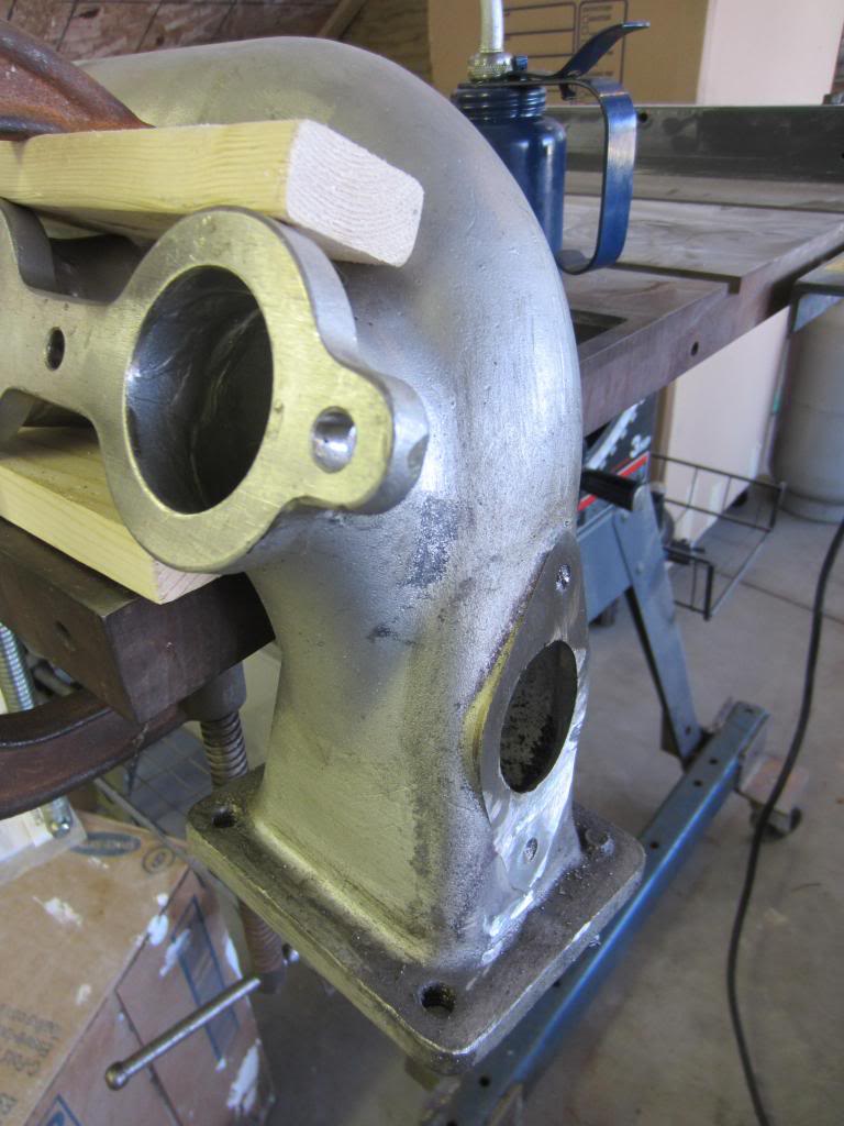
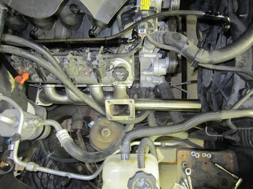
Since the exhaust manifold comes with a small 2 bolt waste gate flange and I want to use that location, I cut that off and welded on a 2" stainless pipe so I can use a 50mm wastegate.
Stainless is not easy to cut. I went through a few previously used sawzall blades.
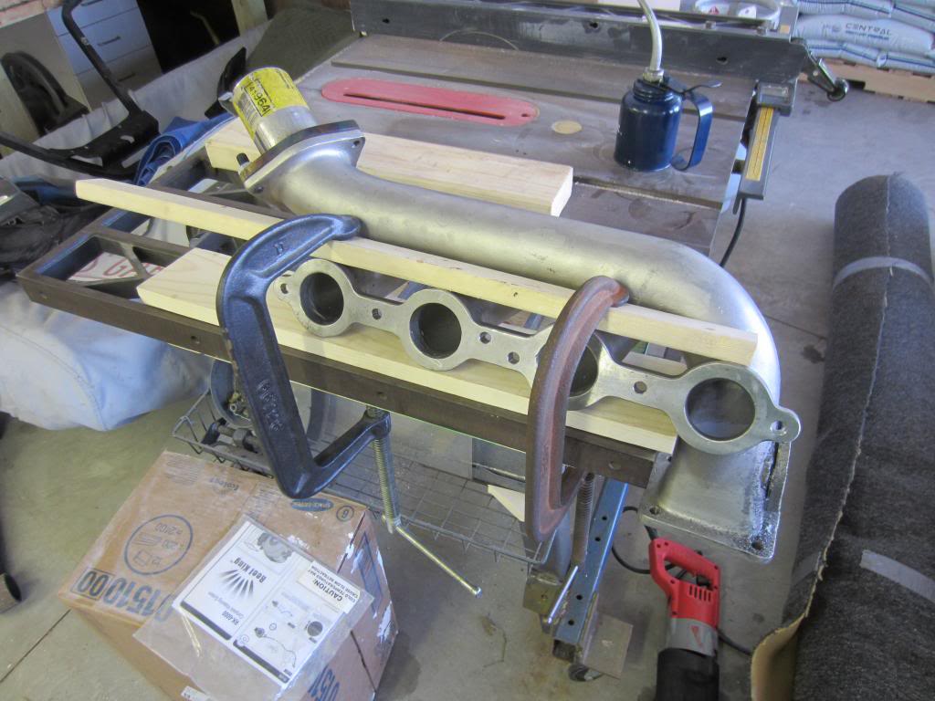
I probably have a total of over an hour cutting time into that.
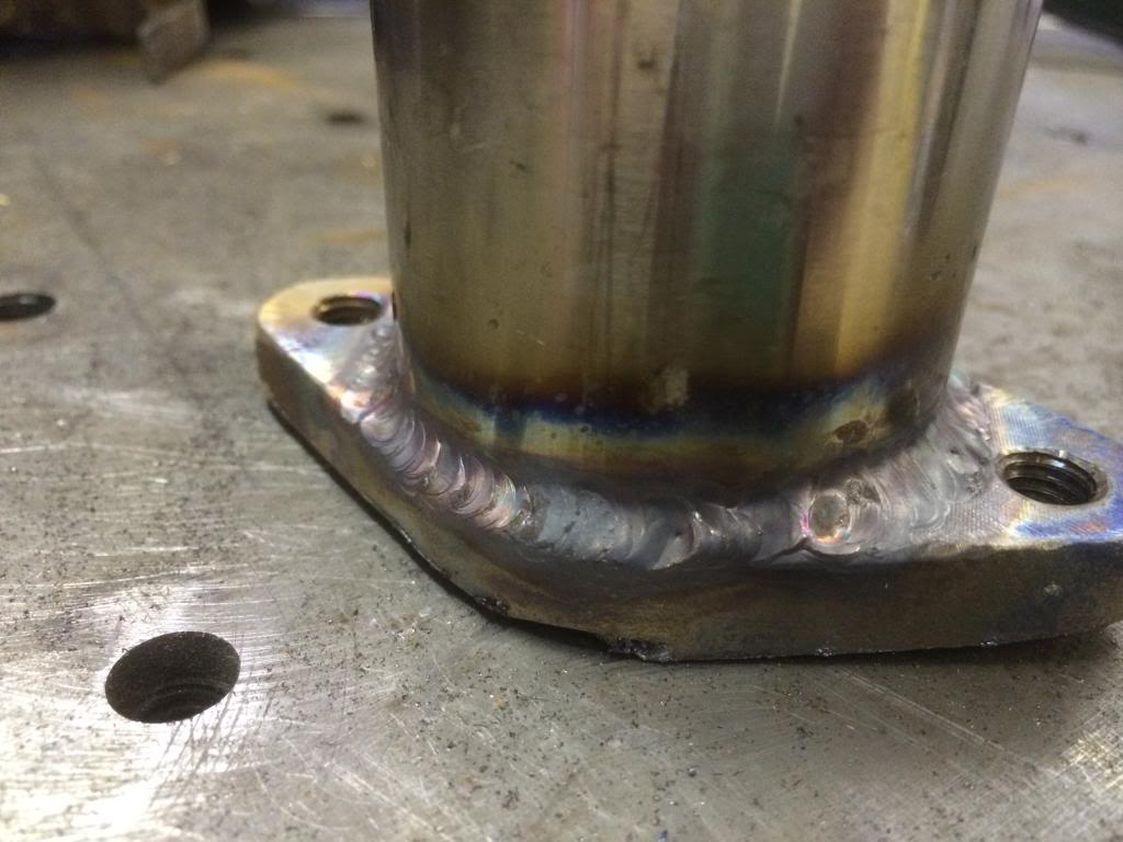
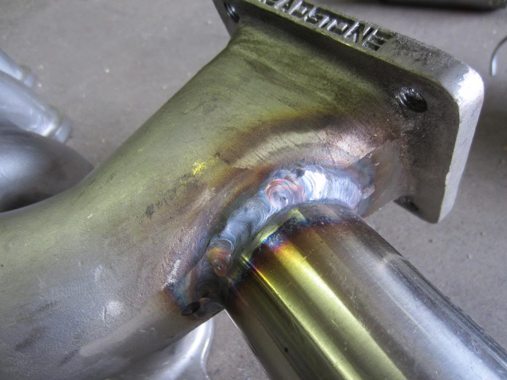
I learned how to tig at a friend's place. This is a test piece using the old flange. About my 2nd time tigging.
Plasma cut a new hole, went from 1.5" to 2"
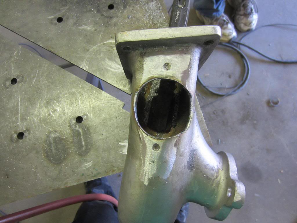
Then went ahead and welded the new pipe on. This is going to get cut down once I have it all situated and get the wastegate location figured out.
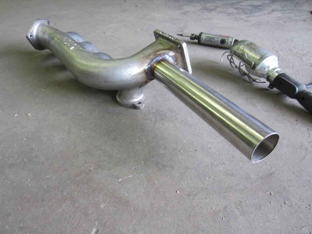
Wastegate will be mounted on a V band, then exit 90* out to the tire and blend with the downpipe.
I've got the oil cooler block installed and the turbo line run from it. -4an has beent he most difficult to terminate yet. Good thing I only have the one line to do.


Then I've been waiting on a few parts so I did some little busy work. I've bveen wanting to do the grille mesh black so I did that finally.

 I have to touch up some of the white.
Since the exhaust manifold comes with a small 2 bolt waste gate flange and I want to use that location, I cut that off and welded on a 2" stainless pipe so I can use a 50mm wastegate.

Stainless is not easy to cut. I went through a few previously used sawzall blades.

I probably have a total of over an hour cutting time into that.

I learned how to tig at a friend's place. This is a test piece using the old flange. About my 2nd time tigging.

Plasma cut a new hole, went from 1.5" to 2"

Then went ahead and welded the new pipe on. This is going to get cut down once I have it all situated and get the wastegate location figured out.


Wastegate will be mounted on a V band, then exit 90* out to the tire and blend with the downpipe.
 May 7, 2014 | 08:20 AM
#68
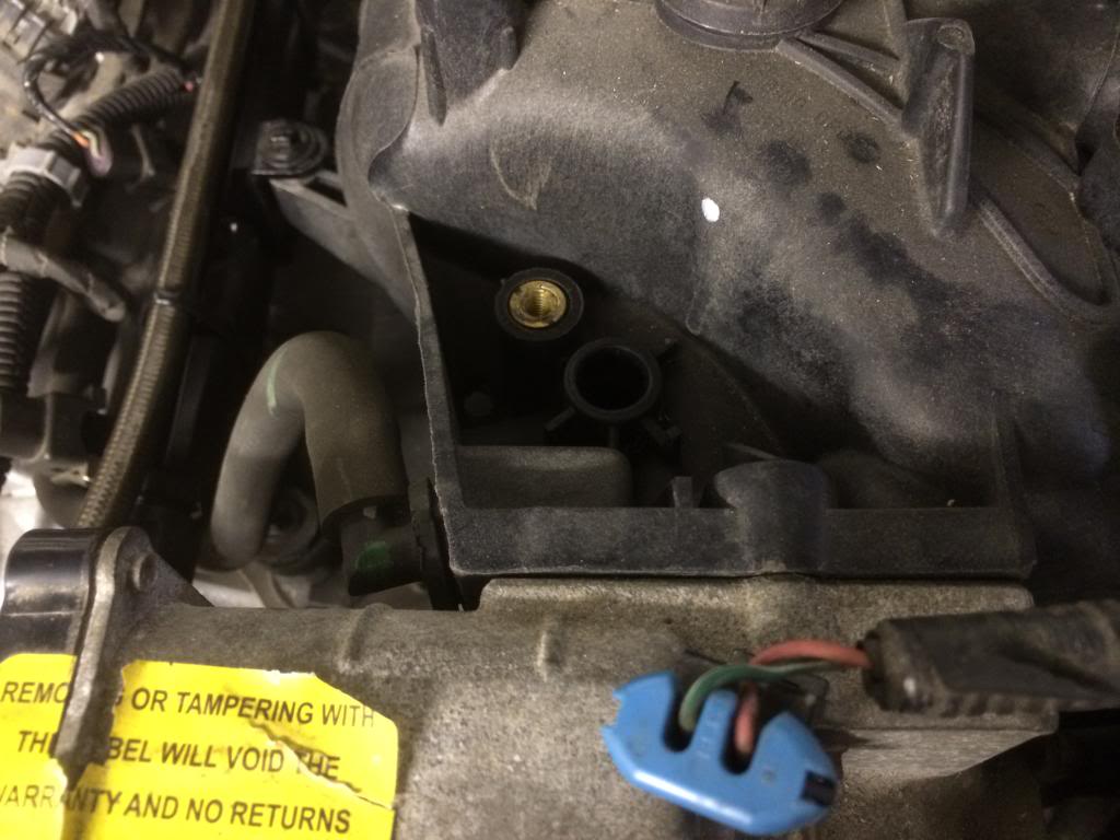
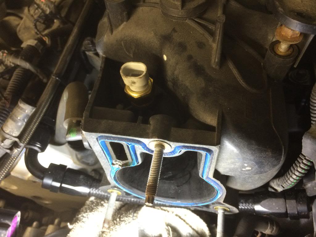
I also added a new IAT since the stock one is built into the MAF and I'm not using that.
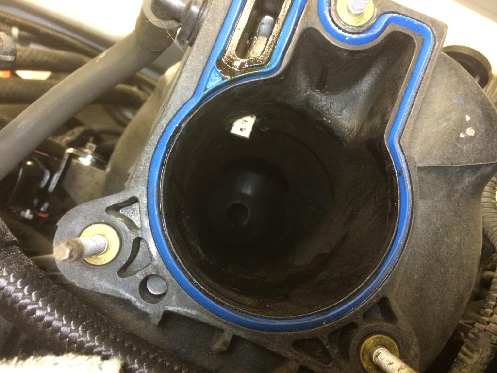
Removed the EVAP solenoid and drilled/tapped it for 3/8 NPT.
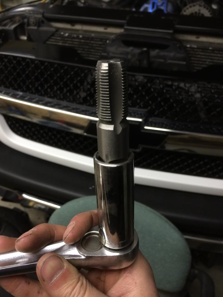
Vacuum cleaner in intake.
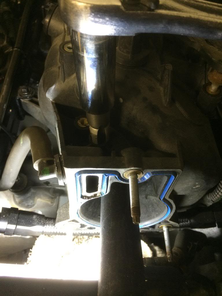
And boom.
Removed the EVAP solenoid and drilled/tapped it for 3/8 NPT.


Vacuum cleaner in intake.

And boom.


 May 7, 2014 | 12:30 PM
#70
A few reasons:
Since deleting the evap, it made perfect use of the hole,
Aluminum pipe absorbs heat and will heat soak the sensor,
When I need to remove the charge pipe, it's one less thing to have to mess with.
Since deleting the evap, it made perfect use of the hole,
Aluminum pipe absorbs heat and will heat soak the sensor,
When I need to remove the charge pipe, it's one less thing to have to mess with.