C7 intake manifold on my 5.3
#12
Staging Lane
Thread Starter
If I lose power I will just switch it back. I have a few of these laying around from installing blowers on c7s. None are for sale so please don't ask. I have a c7 throttle body and a gmc Sierra one so I will try both. I have a tube made up with a 45 upward. I have all the isolators. Also you will not be able to use your truck foam isolator between the valley and manifold. You have to use the C7 one. At least on the 5.3
#13
I've studied the hp and torque curves of the 6.2 LT1 vs L86. It looks like installing the C7 intake manifold on the 6.2 truck will leave the torque level about the same but move it about 500 rpms up in the rpm range. So unless the truck is used primarily for heavy towing at low rpm, that should be fine. The hp should see a nice increase above 5,000 rpm, maybe 30 hp increase.
I received mine yesterday. I will definitely have to make a new intake tube from the air box to the throttle body. The truck has the throttle body angled upward. the C7 has it angled downward. I'll order some individual parts from Airaid's U-Build-It intake kits. No problem there.
I cleaned up the inlet and the exit of the runners. mainly just smoothing out the friction welds. But on the inlet, I removed the PCV tube that ran directly across the path of the incoming air. I know GM engineers put it there for a reason but it's gone now.
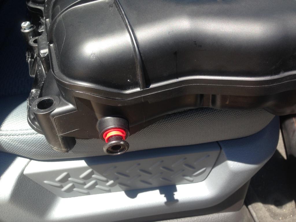
I do have a question. On the rear of the C7 intake there looks to be a plug. It's on the driver's side. Black plastic plug with a red bushing or something. Anyone know what that is for? I have not removed my truck intake manifold yet but I'm guessing some tube or hose will connect there?
#14
Staging Lane
Thread Starter
I've studied the hp and torque curves of the 6.2 LT1 vs L86. It looks like installing the C7 intake manifold on the 6.2 truck will leave the torque level about the same but move it about 500 rpms up in the rpm range. So unless the truck is used primarily for heavy towing at low rpm, that should be fine. The hp should see a nice increase above 5,000 rpm, maybe 30 hp increase.
I received mine yesterday. I will definitely have to make a new intake tube from the air box to the throttle body. The truck has the throttle body angled upward. the C7 has it angled downward. I'll order some individual parts from Airaid's U-Build-It intake kits. No problem there.
I cleaned up the inlet and the exit of the runners. mainly just smoothing out the friction welds. But on the inlet, I removed the PCV tube that ran directly across the path of the incoming air. I know GM engineers put it there for a reason but it's gone now.
I do have a question. On the rear of the C7 intake there looks to be a plug. It's on the driver's side. Black plastic plug with a red bushing or something. Anyone know what that is for? I have not removed my truck intake manifold yet but I'm guessing some tube or hose will connect there?
I received mine yesterday. I will definitely have to make a new intake tube from the air box to the throttle body. The truck has the throttle body angled upward. the C7 has it angled downward. I'll order some individual parts from Airaid's U-Build-It intake kits. No problem there.
I cleaned up the inlet and the exit of the runners. mainly just smoothing out the friction welds. But on the inlet, I removed the PCV tube that ran directly across the path of the incoming air. I know GM engineers put it there for a reason but it's gone now.
I do have a question. On the rear of the C7 intake there looks to be a plug. It's on the driver's side. Black plastic plug with a red bushing or something. Anyone know what that is for? I have not removed my truck intake manifold yet but I'm guessing some tube or hose will connect there?
#15
That goes to the brake booster and vacuum pump on the vette. I'm my truck it does not go there it goes to the vacuum pump by the crank pulley so I used the factory corvette pushlock fitting to plug it and a rubber vaccum cap on the end of that. It's a two inch long fitting angled at a 45. It's the easier way rather then drilling and tapping a pipe plug in
#17
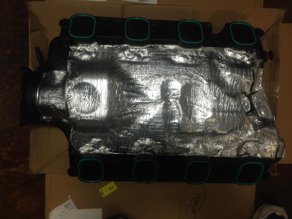
any updates on the 5.3 install? I cleaned up the inlet and outlet ports and insulated the outside of the manifold. My parts for the custom intake tube should arrive in a day or two. I need to reliably pull a jetski this weekend, so...I may wait until Sunday evening or early next week to install it. I don't want to take a chance of having an issue before Friday. If I can be patient that long. On the insulation: I have heard someone say to reduce heat soak, remove the cover. But my thinking is, the cool air is going to be on the inside. The hot air is going to be on the outside. So it makes more sense to do a better job of insulating it from the heat than exposing it to it. The factory insulator leaves a lot of exposed surface to the engine heat. Especially the underside which will be exposed to the 200+ degree engine with no air flow around it. I'm thinking that is the main source foe heat sink. I'll get some pictures later and post them.
#18
Staging Lane
Thread Starter
any updates on the 5.3 install? I cleaned up the inlet and outlet ports and insulated the outside of the manifold. My parts for the custom intake tube should arrive in a day or two. I need to reliably pull a jetski this weekend, so...I may wait until Sunday evening or early next week to install it. I don't want to take a chance of having an issue before Friday. If I can be patient that long. On the insulation: I have heard someone say to reduce heat soak, remove the cover. But my thinking is, the cool air is going to be on the inside. The hot air is going to be on the outside. So it makes more sense to do a better job of insulating it from the heat than exposing it to it. The factory insulator leaves a lot of exposed surface to the engine heat. Especially the underside which will be exposed to the 200+ degree engine with no air flow around it. I'm thinking that is the main source foe heat sink. I'll get some pictures later and post them.
#19
Factory C7 foam? Rot Row Shaggy. Didn't know about that. So there's a foam insulation under the C7 manifold that the truck manifold doesn't have?
I figured some wiring would have to be extended. There's one sensor on the driver side of the truck manifold inlet that will move to the passenger side of the C7 manifold (guessing that's IAT sensor?). And I see the C7 manifold has a place for a sensor on the top passenger side of the manifold (guessing that's for the MAP sensor?).
I figured some wiring would have to be extended. There's one sensor on the driver side of the truck manifold inlet that will move to the passenger side of the C7 manifold (guessing that's IAT sensor?). And I see the C7 manifold has a place for a sensor on the top passenger side of the manifold (guessing that's for the MAP sensor?).
Last edited by typhoon186; 08-19-2014 at 11:45 AM.


