
4L60E to 4L80E Wiring Swap
 Mar 4, 2008 | 11:37 PM
#1

Thread Starter
TECH Senior Member
iTrader: (10)
Joined: Oct 2004
Posts: 14,068
Likes: 2
From: Crystal Springs, MS
Edited: all info on this post..
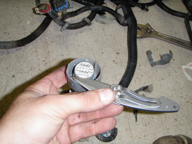
How to swap wires.
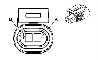
Transmission connector:
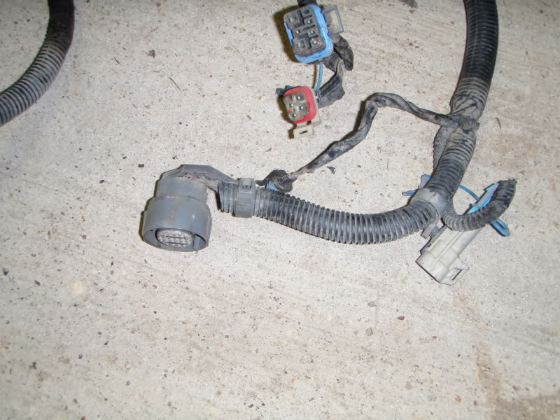
Remove cover:
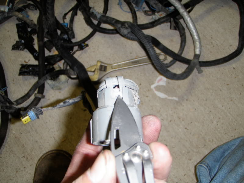
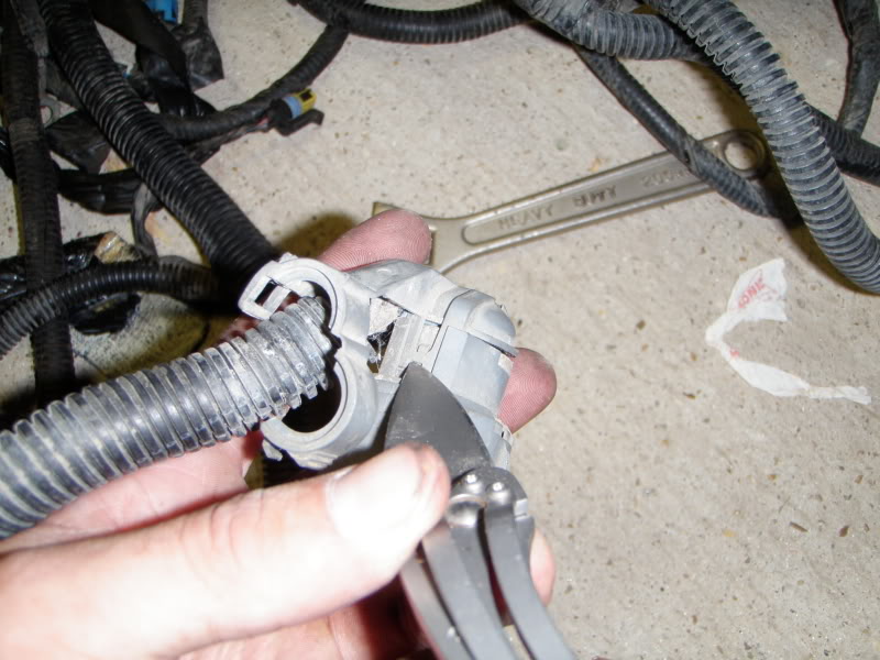
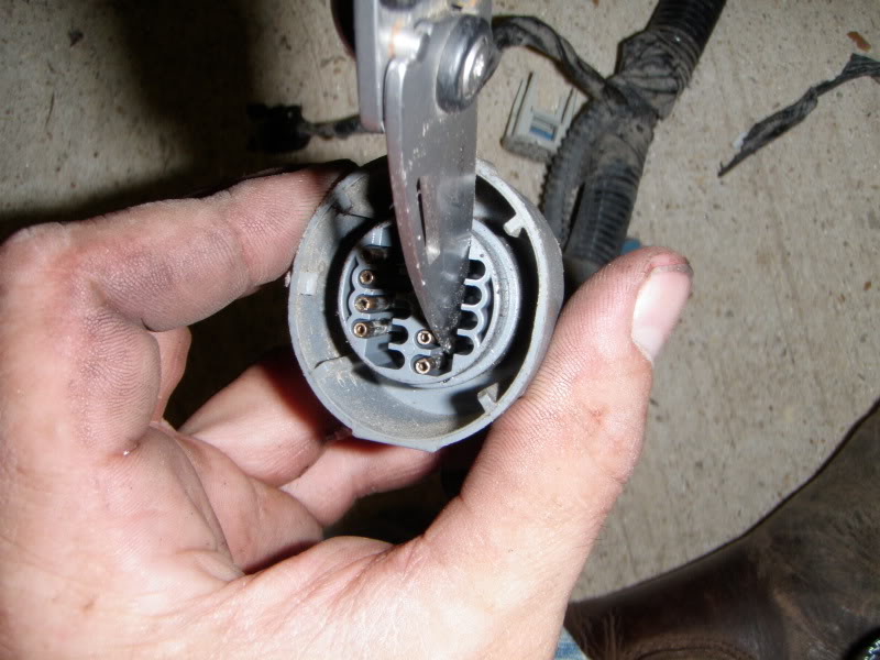
Remove white end:
Small knife works good to bend the lil grey clip back to remove the ends:
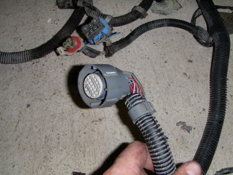
Put the white piece back on, the grey cover, and your finished, that easy.
After all that work,,, i think this 2004 harness is already a 80E harness
How to swap wires.
Transmission connector:
Remove cover:
Remove white end:
Small knife works good to bend the lil grey clip back to remove the ends:
Put the white piece back on, the grey cover, and your finished, that easy.
After all that work,,, i think this 2004 harness is already a 80E harness
Last edited by nonnieselman; Sep 29, 2009 at 09:17 PM.
Mar 5, 2008 | 12:29 AM
#2
Thread Starter
TECH Senior Member
iTrader: (10)
Joined: Oct 2004
Posts: 14,068
Likes: 2
From: Crystal Springs, MS
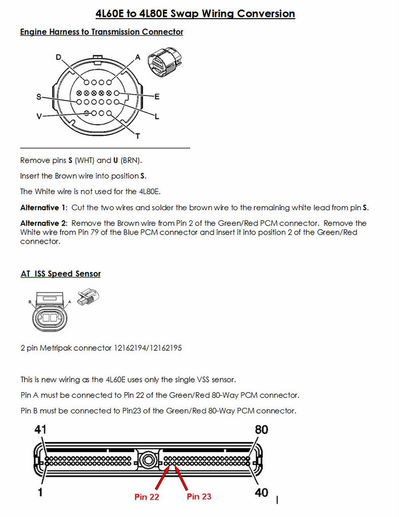
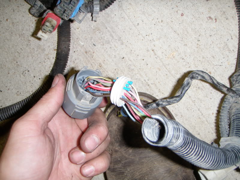
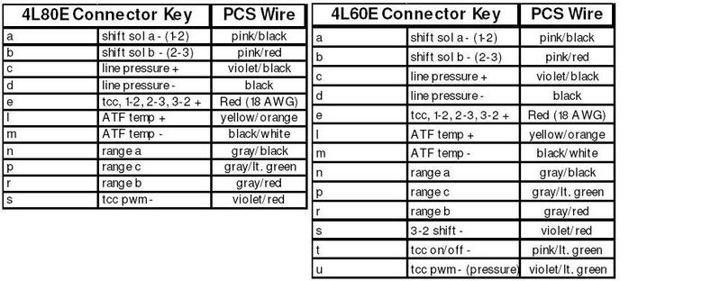
The 60e has 13 wires in the connector..

The 80e has 11 wires in the connector..
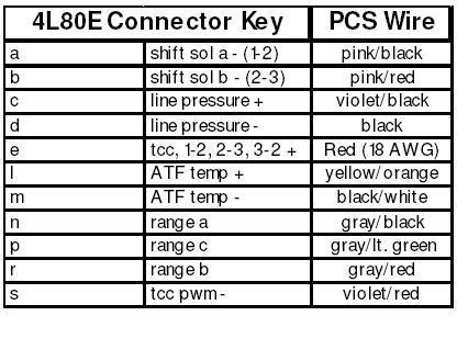
I put both the pics together so it does look like removing 2 wires and moving one of them should do the trick.. i just need a diagram of a 80E to verify.
The 80e has 11 wires in the connector..
I put both the pics together so it does look like removing 2 wires and moving one of them should do the trick.. i just need a diagram of a 80E to verify.


 Mar 9, 2008 | 02:41 PM
#6

What you said looks correct for your model year. Don't think you have to bother pulliing # 42 Red as there will be nothing connected to it on the trans side anyway. Just move the #79 Blue to #2 Red.
Or you could just pull pins S (WHT) and U (BRN) at the trans connector, move the BRN wire to the S position, and leave the white disconnected (or put it in the now unused U position for safekeeping).
Plus you will require the additional AT ISS sensor connected to pins 22 and 23 of your red PCM connector. Pin A to Pin 22, Pin B to Pin 23.
Let us know how it works out.
Last edited by DrX; Mar 9, 2008 at 03:24 PM.
Trending Topics
Mar 17, 2008 | 08:25 AM
#9
Good to hear!
The PCM pin positions will be a little different for newer trucks with the Blue and Green connectors. But if you swap the pins at the trans connector it will be the same procedure. The speed sensor will be connected to pins 22 and 23 of the Green connector.
The PCM pin positions will be a little different for newer trucks with the Blue and Green connectors. But if you swap the pins at the trans connector it will be the same procedure. The speed sensor will be connected to pins 22 and 23 of the Green connector.