Diy aux input on a factory radio
 May 12, 2011 | 09:28 PM
#1

BACKGROUND: when using my "truckputer" when driving a distance, my fm transmitter would fade in and out and i would get interference and have to adjust fm frequencies to compensate for different local radio stations. i also want to keep the factory radio because i like my steering wheel controls. This is a problem because the factory radio has on AUX inputs
SOLUTION: wire a aux input into factory radio
WHY BUILD IT: because i can and 20 minutes +under 10$=80$-150$ part
**the starting point of this DIY is assuming that you have the radio all ready out of the dash and sitting in front of you**
***I take no responsibility�s of ANYTHING you do to your truck/ do this at your own risk***
Lets get started.
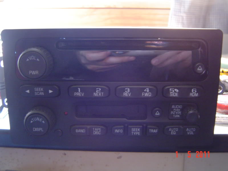
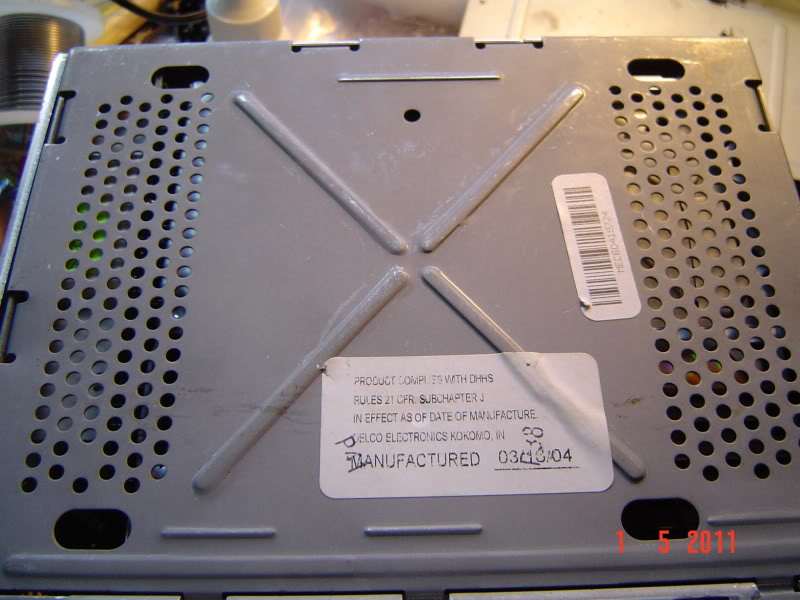
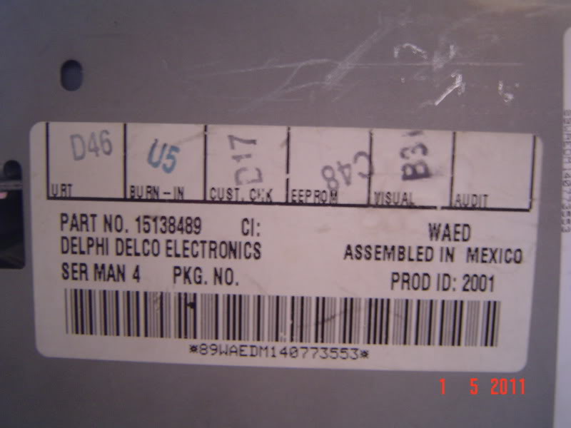
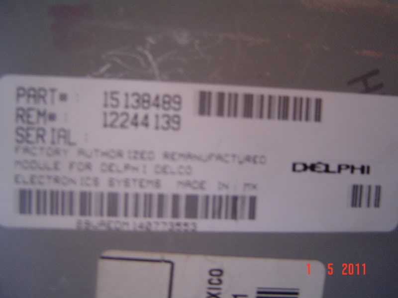
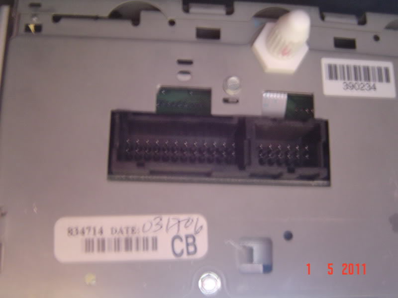
this is the radio I preformed the mod to its the OEM unit from my 04 Silverado rcsb. the part number and other identifiers are in the pics
we'll start by flipping the radio over to the bottom (cd drive facing down) and using a flat blade screw driver to gently pry along the perimeter of the bottom plate until you can lift the back (back=by radio connections from truck) in the direction of the face plate and then remove it
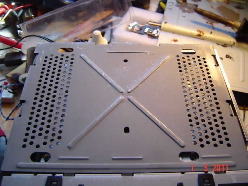
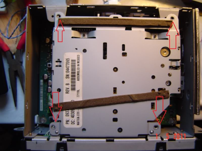
then we remove the 4 screws that hold in the tape deck
SOLUTION: wire a aux input into factory radio
WHY BUILD IT: because i can and 20 minutes +under 10$=80$-150$ part
**the starting point of this DIY is assuming that you have the radio all ready out of the dash and sitting in front of you**
***I take no responsibility�s of ANYTHING you do to your truck/ do this at your own risk***
Lets get started.
this is the radio I preformed the mod to its the OEM unit from my 04 Silverado rcsb. the part number and other identifiers are in the pics
we'll start by flipping the radio over to the bottom (cd drive facing down) and using a flat blade screw driver to gently pry along the perimeter of the bottom plate until you can lift the back (back=by radio connections from truck) in the direction of the face plate and then remove it
then we remove the 4 screws that hold in the tape deck
May 12, 2011 | 09:30 PM
#2
after the screws are removed gently pick up the tape deck and unplug the 2 connectors on the unit by pulling them straight out
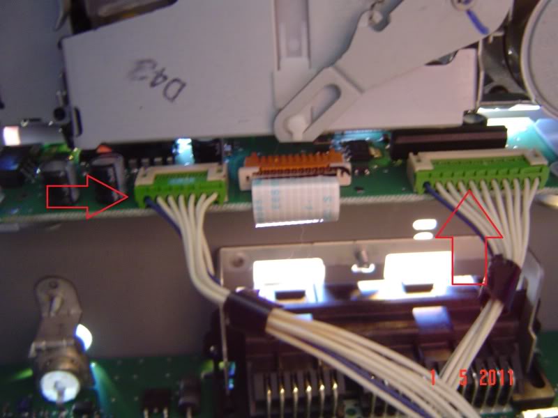
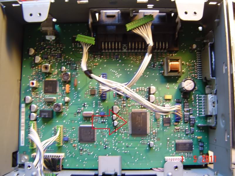
we now have access to the main board of the radio and you can finally see the chip we are interested in
now its time to make the AUX input wire, i used a rca to 3.5 mm jack wire i got from ebay for 7$. first thing i did was cut off the 3.5mm jack end
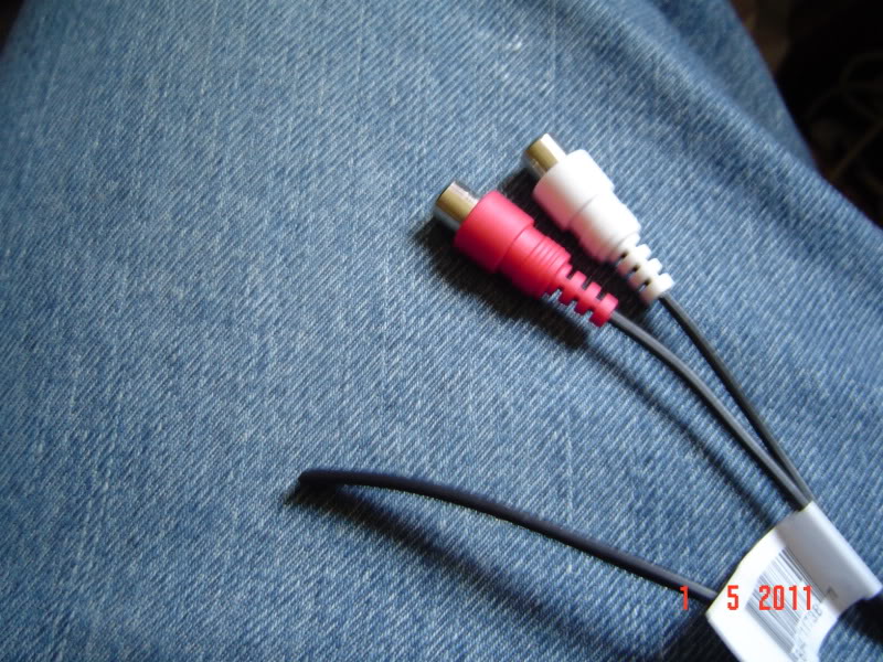
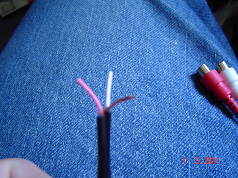
i then used a wire stripper to strip the plastic casing from the 2 wires exposing 2 smaller coated wires (left and right signal wires) and a bunch of uncoated wire (ground wire). Next step is to gather the ground wire together like so and strip the ends of the 2 signal wires
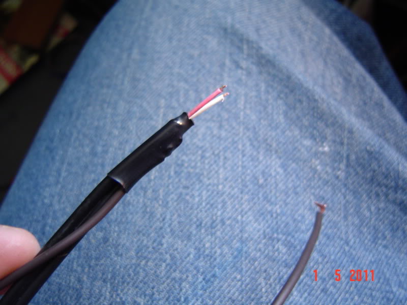
solder a wire extension to the ground wire and use a peace of heat shrink to seal it
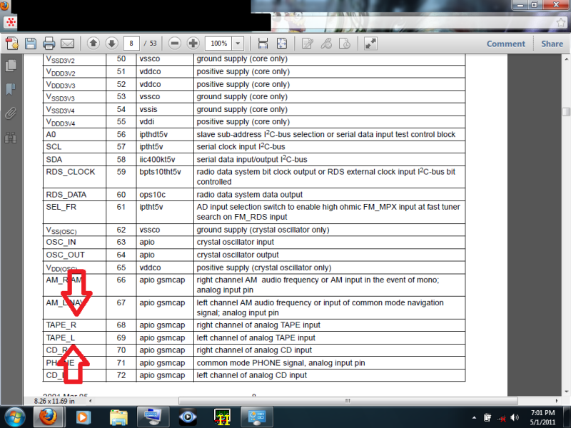
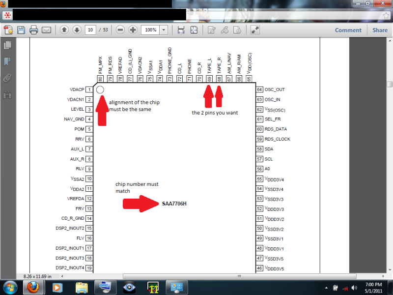
now we are ready to do the mod. here is some more info from the data sheet on the chip, along with the 2 points we want
on the radio main board the points we want are right here
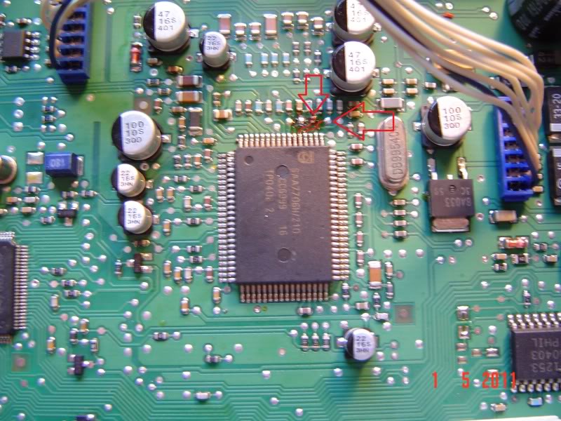
solder the 2 signal wires to the 2 solder points
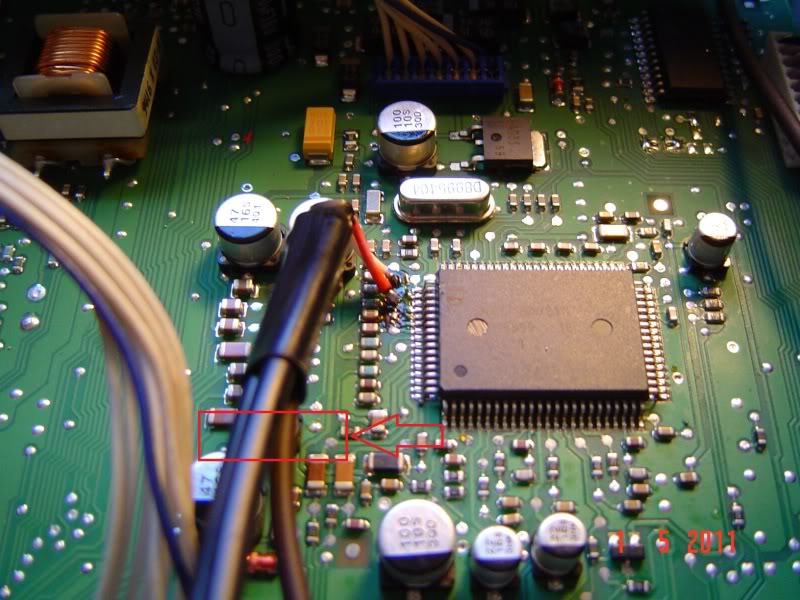
then solder your ground to a ground point on the board, i chose this ground pad
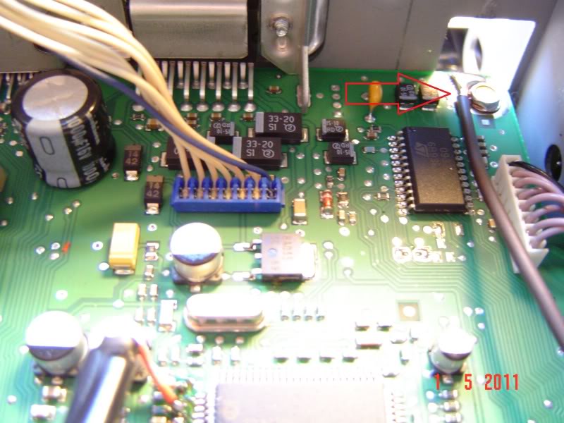
apply hot glue here to help the wire stay in one place and not stress the solder points
we now have access to the main board of the radio and you can finally see the chip we are interested in
now its time to make the AUX input wire, i used a rca to 3.5 mm jack wire i got from ebay for 7$. first thing i did was cut off the 3.5mm jack end
i then used a wire stripper to strip the plastic casing from the 2 wires exposing 2 smaller coated wires (left and right signal wires) and a bunch of uncoated wire (ground wire). Next step is to gather the ground wire together like so and strip the ends of the 2 signal wires
solder a wire extension to the ground wire and use a peace of heat shrink to seal it
now we are ready to do the mod. here is some more info from the data sheet on the chip, along with the 2 points we want
on the radio main board the points we want are right here
solder the 2 signal wires to the 2 solder points
then solder your ground to a ground point on the board, i chose this ground pad
apply hot glue here to help the wire stay in one place and not stress the solder points
May 12, 2011 | 09:31 PM
#3
reassemble the radio and test it and if everything is correct and working your done! Now have a AUX input! to make the radio have the tape input option you must insert a tape in the tape deck, it can be any tape even one with nothing on it
TESTING
(Sorry for it being so dark and me fumbling around with the touch screen, its hard to do with your none dom. hand looking at it with the camera with out a stylist)
http://s181.photobucket.com/albums/x...t=MOV01523.mp4
http://s181.photobucket.com/albums/x...t=MOV01522.mp4
i have tested it on my application (truckputer) but not a ipod so i don’t know for sure if it will work for one
OTHER THINGS I WANT TO TALK ABOUT:
since i will never use my tape player i inserted my tape in the tape deck when i hade the radio apart so the dust door will stay down with the tape in it to make it look better. Some of you will say that this is the same thing as a tape insert with a 3.5mm jack on it used to plug in a cd player (big thing in the 90's) to that i say yes and no
YES: you do need a tape in the tape deck just so it gives you a option to switch to the tape deck, this could be done away with more soldering
NO: in the 90's tape to 3.5mm adapter all the sounds/data from your cd player would have to go past the tape heads bring the audio quality of a cd down to tape levels, with this mod the heads don’t do anything all the data go’s directly to the chip.
Questions or things i can elaborate on please ask
May 13, 2011 | 04:44 PM
#4


Where do you get data sheets like that? Am I going to have to SawZall the radio out of my dash to get a number off of its chip? Would those inputs be in my radio if they're not used? Mine is a stock, AM/FM, no CD or cassette players.
May 13, 2011 | 07:53 PM
#5
this was done on a 04 silverado rcsb 4x4
data sheets are on the net, search for "XXXXXXXX data sheet" (XXXXX is the number on the chip)
depending on the truck the dash bezel should pop out and you simply unscrew the radio mounting screws but a SawZall is always a viable option
what year and make truck is yours?
data sheets are on the net, search for "XXXXXXXX data sheet" (XXXXX is the number on the chip)
depending on the truck the dash bezel should pop out and you simply unscrew the radio mounting screws but a SawZall is always a viable option
what year and make truck is yours?
Last edited by beingblueeyes; May 13, 2011 at 07:59 PM.
 May 13, 2011 | 08:13 PM
#7
It's as 2000 GMC Sierra 2500. This is such an excellent mod that I don't want to get my hopes up if my radio-only radio might not be capable. I know it would only take maybe 10 minutes to get the radio out, but I am thinking this would be a nice foul-weather project.