
Wiring ? Efans and Radix intercooler pump
 Mar 18, 2008 | 03:30 PM
#11
So, if you do the above here is how it would work.
flip switch one = both fans on low and pump activated.
flip switch two= triggers fans to come on high ((ONLY)) if switch one is on!
flip switch one = both fans on low and pump activated.
flip switch two= triggers fans to come on high ((ONLY)) if switch one is on!
Mar 18, 2008 | 04:12 PM
#12

I am going to try with just one switch first. I think 2 fans on the low speed setting will be sufficient and preserve the battery. I am going to buy the relay you cited above. I already have a wire running from my battery (from my air bag compressor) that I will tap into for the power source.
Thanks for all your help!!!!!!
Mar 18, 2008 | 07:45 PM
#13
It's late and I don't want to think to much.... but I think I see a problem with the wiring as drawn. We aren't taking into account the normal engine running and IC pump run that is already wired up. I do it all the time. I presently have a switch in cab to run my e-fans manually if I want. I don't always remember to turn them off. If I happened to have this wired up and I started my truck I think I'd then have a dead short at the IC pump. I think you would need another set of contacts on a relay that killed the "normal" power to the IC pump when you had the fans on manually.
Last edited by KySilverado; Mar 18, 2008 at 08:01 PM.
Mar 18, 2008 | 08:07 PM
#14
It's late and I don't want to think to much.... but I think I see a problem with the wiring as drawn. I do it all the time. I presently have a switch in cab to run my e-fans manually if I want. I don't always remember to turn them off. If I happened to have this wired up and I started my truck I think I'd then have a dead short at the inter-cooler pump. I think you would need another set of contacts on the relay that killed the "normal" power to the intercooler pump when you had the fans on manually.
Basically all he is doing is grounding out his PCM pin to activate the fans. We are not using any power from the fans..
For the pump we are doing the same thing. We have power from the relay and when we ground the activation wire it completes the circuit.
Assume the pump has power and we turn the truck on..
basically you would just have two power wires feeding the pump.
Am I missing something here?
How are these intercooler pumps wired?
Does it have its on relay?
Last edited by Derek @ EDO; Mar 18, 2008 at 08:18 PM.
Mar 18, 2008 | 08:13 PM
#15
I dont understand. This is a ground activted schematic.
Basically all he is doing is grounding out his PCM pin to activate the fans.
For the pump we are doing the same thing. We have power from the relay and when we ground the activation wire it completes the circuit.
Assume the pump has power and we turn the truck on..
basically you would just have two power wires feeding the pump.
Am I missing something here?
 Mar 18, 2008 | 08:29 PM
#16
 Mar 18, 2008 | 09:05 PM
#17
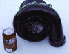
Okay, I am home now. I looked at the intercooler pump. There is a red and black wire. Here is what it looks like:

I am assuming I can tap into the red wire? But can I do the same for the black wire?? Or does that need to go to a ground?
I am assuming I can tap into the red wire? But can I do the same for the black wire?? Or does that need to go to a ground?
 Mar 18, 2008 | 09:18 PM
#20