


Electric Fans - Pin 33
 Apr 8, 2009 | 05:01 PM
#42


 I promise im not completely dumb....
i wasnt even payin attn to the diagram. But yes run the wire thats suppose to go to the AC ground to the PCM pin 33 and activate it in the tune and Vola..
 , just clarifying for the guys that are wanting to do it.
  Apr 8, 2009 | 06:43 PM
#45

Thread Starter
TECH Senior Member
iTrader: (7)
Joined: Jun 2004
Posts: 5,446
Likes: 7
From: Central Kentucky
For the question of this working with 02 pcms.... there have been a lot of diagrams posted on wiring. I haven't traced them all out. The original GM wiring diagram thats been posted is what I used and I know it works the way GM intended them to work. Not saying the others posted don't.... It's not the wiring diagram thats really important. It's will the 99-02 PCM control pins 33 and 42 and it appears it does from Noonies' experience.
Apr 8, 2009 | 06:57 PM
#46
For the question of this working with 02 pcms.... there have been a lot of diagrams posted on wiring. I haven't traced them all out. The original GM wiring diagram thats been posted is what I used and I know it works the way GM intended them to work. Not saying the others posted don't.... It's not the wiring diagram thats really important. It's will the 99-02 PCM control pins 33 and 42 and it appears it does from Noonies' experience.
 JK..
JK..The Fbodies have the same setup with 3 relays and pin 33 and 42
i copied and pasted My buddys 99 Trans am stock settings to my tune to get an idea how GM has it set.
Ive made harnesses, installed Efans, Tuned my 2000 with a 02 pcm.. my buddy's 04 Silverado, a 03 Tahoe, and adjusted my buddys 99 Trans Am Efan settings..
So yea it works

Anyone can PM me if they need help with this.
Apr 8, 2009 | 07:01 PM
#47

So this is not correct?
The AC clutch engage signal wire is not activated with a ground.. It activates with +.
An older style harness would have to be rewired to accept a ground activation for both low and high speeds. Ive built a few like this, I use the GM schematic and its indeed different from the older clutch activated harness schematic.
Derek
An older style harness would have to be rewired to accept a ground activation for both low and high speeds. Ive built a few like this, I use the GM schematic and its indeed different from the older clutch activated harness schematic.
Derek
Apr 8, 2009 | 07:12 PM
#48


Are the 05 fans two speed fans as in do they have 4 settings they operate in?
fan 1 - low
fan 1 - high
fan 1 and fan 2 - low
fan 1 and fan 2 - high
...what are the run speeds of the fans is what I am asking i guess?
fan 1 - low
fan 1 - high
fan 1 and fan 2 - low
fan 1 and fan 2 - high
...what are the run speeds of the fans is what I am asking i guess?
Apr 8, 2009 | 07:23 PM
#49
with this diagram...
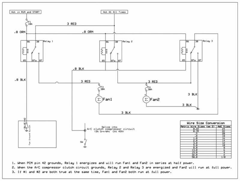
Read the bottom of the diagram
You will have Fans 1 & 2 on low speed- Fan 2 on high speed- or Fans 1 & 2 on high speed.
Apr 8, 2009 | 07:47 PM
#50
Thread Starter
TECH Senior Member
iTrader: (7)
Joined: Jun 2004
Posts: 5,446
Likes: 7
From: Central Kentucky
Sorry  I even spelled it wrong below again and fixed it
What Derek posted is absolutely correct.
Just as Nonnie states, the fans are just one speed. Depending on how the relays are activated the 12v fans are either run in a series circuit or a parallel circuit. In series they are basically seeing 6v each and run at a lower speed. When they are in parallel they each see 12v and run at full speed. One fan is also isolated and will run full speed in one instance.
I even spelled it wrong below again and fixed it What Derek posted is absolutely correct.
Just as Nonnie states, the fans are just one speed. Depending on how the relays are activated the 12v fans are either run in a series circuit or a parallel circuit. In series they are basically seeing 6v each and run at a lower speed. When they are in parallel they each see 12v and run at full speed. One fan is also isolated and will run full speed in one instance.
Last edited by KySilverado; Apr 8, 2009 at 07:58 PM.