
still cant race anyone!!!!
 May 30, 2006 | 08:24 PM
#1
well i have fixed all the other problems on my truck except for the problem with the computer shutting it down. thanks again for all you guys help. but i really need some expert help with this one. its throwing a U0107 code which is lost communication with throttle body accuator. when it does this it shuts the truck down to an idle and says reduced engine power. if anyone knows what the problem could be please chime in. thanks
May 30, 2006 | 09:43 PM
#2

Launching!

Joined: May 2005
Posts: 280
Likes: 0
From: Ada, Oklahoma
i have seen this code before at the dealership, there is a yellow or orange wire going the the TAC throttle body, i cant remember which color. anyway this wire usually has a bad connection or is broken. If it is not the wire GM has a bulletin out for the TAC module and i have replaced many of these for this problem. This is the module just beside your brake booster on the firewall. Its not hard to change and doesnt require any reprograming. Good luck.
May 30, 2006 | 09:48 PM
#3


Originally Posted by gmtechnician
i have seen this code before at the dealership, there is a yellow or orange wire going the the TAC throttle body, i cant remember which color. anyway this wire usually has a bad connection or is broken. If it is not the wire GM has a bulletin out for the TAC module and i have replaced many of these for this problem. This is the module just beside your brake booster on the firewall. Its not hard to change and doesnt require any reprograming. Good luck.
May 31, 2006 | 11:53 AM
#4
Originally Posted by gmtechnician
i have seen this code before at the dealership, there is a yellow or orange wire going the the TAC throttle body, i cant remember which color. anyway this wire usually has a bad connection or is broken. If it is not the wire GM has a bulletin out for the TAC module and i have replaced many of these for this problem. This is the module just beside your brake booster on the firewall. Its not hard to change and doesnt require any reprograming. Good luck.
 May 31, 2006 | 02:57 PM
#6

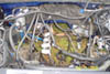
FYI, I got that code when my hood was up in a rain. The wire harness from the TB to the TAC had moisture in it at the TAC connection. I pulled it off and it appeared dry but I blew it out with compressed air and tried it again. No issues.
Can you link me to your other threads?
Can you link me to your other threads?
May 31, 2006 | 03:21 PM
#7
here ya go. this is the thread concerning this problem.
https://www.performancetrucks.net/fo...d.php?t=365611
https://www.performancetrucks.net/fo...d.php?t=365611
Trending Topics
 May 31, 2006 | 07:19 PM
#9

Here is the flow chart if that helps... if you need the schematic, I will try to get it on here...
1
Did you perform the Diagnostic System Check - Engine Controls?
--
Go to Step 2
Go to Diagnostic System Check - Engine Controls
2
Turn ON the ignition, with the engine OFF.
Remove the cover from the underhood electrical center.
Test both sides of the ETC fuse with a test lamp connected to ground.
Does the test lamp illuminate on at least one side of the fuse?
--
Go to Step 3
Go to Ignition Relay Diagnosis
3
Turn OFF the ignition
Test for voltage at the ETC fuse with a test lamp connected to ground.
Does the test lamp illuminate?
--
Go to Step 22
Go to Step 4
4
Connect a scan tool.
Is DTC P0604 also set?
--
Go to DTC P0601-P0607, P1600, P1621, P1627, P1680, P1681, P1683, or P2610
Go to Step 5
5
Important
If the Driver Information Center is displaying Reduced Engine Power, go to Step 6.
Start the engine.
Increase the engine speed to 3,000 RPM, if possible.
Monitor the DTC Info option using the scan tool.
Does the scan tool indicate this DTC failed this ignition?
--
Go to Step 6
Go to Diagnostic Aids
6
Turn OFF the ignition.
Disconnect the throttle actuator motor harness connector.
Turn ON the ignition, with the engine OFF.
Test for voltage at both throttle actuator motor control circuits with a DMM.
Does the DMM indicate voltage on both circuits above the specified value?
1 V
Go to Step 12
Go to Step 7
7
Turn OFF the ignition.
Disconnect the throttle actuator control (TAC) module connectors.
Test both throttle actuator motor control circuits for continuity to ground with a DMM.
Does the DMM indicate continuity to ground?
--
Go to Step 10
Go to Step 8
8
Turn OFF the ignition.
Remove the ETC fuse.
Test the TAC side of the fuse terminal for continuity to ground with a DMM. Refer to Diagnostic Aids for terminal identification table.
Does the DMM indicate continuity to ground?
--
Go to Step 9
Go to Step 11
9
Disconnect the TAC module 16-way harness connector.
Test the TAC side of the fuse terminal for a short to ground with a DMM. Refer to Circuit Testing and Wiring Repairs in Wiring Systems.
Did you find and correct the condition?
--
Go to Step 28
Go to Step 24
10
Disconnect the TAC module 16-way harness connector.
Test the throttle actuator motor control circuits for a short to ground at the TAC module 16-way harness connector with a DMM. Refer to Circuit Testing and Wiring Repairs in Wiring Systems.
Did you find and correct the condition?
--
Go to Step 28
Go to Step 24
11
Turn OFF the ignition.
Disconnect the TAC module 16-way harness connector.
Test the TAC module ignition feed circuit for an open or high resistance with a DMM. Refer to Circuit Testing and Wiring Repairs in Wiring Systems.
Did you find and correct the condition?
--
Go to Step 28
Go to Step 24
12
Turn OFF the ignition.
Disconnect the TAC module 16-way connector.
Turn ON the ignition, with the engine OFF.
Test for a short to voltage at both throttle actuator motor control circuits with a DMM. Refer to Circuit Testing and Wiring Repairs in Wiring Systems.
Did you find and correct the condition?
--
Go to Step 28
Go to Step 13
13
Turn OFF the ignition.
Disconnect the TAC module 10-way harness connector.
Test for a short between each throttle actuator motor control circuit and all other TAC module circuits with a DMM. Refer to Circuit Testing and Wiring Repairs in Wiring Systems.
Did you find and correct the condition?
--
Go to Step 28
Go to Step 14
14
Test for an open or high resistance in the TAC module ground circuit with a DMM. Refer to Circuit Testing and Wiring Repairs in Wiring Systems.
Did you find and correct the condition?
--
Go to Step 28
Go to Step 15
15
Test for voltage on the serial data circuits at the TAC module 16-way harness connector with a DMM.
Does the DMM indicate voltage within the specified values for both circuits?
0-4.5 V
Go to Step 16
Go to Step 18
16
Turn OFF the ignition.
Test both serial data circuits at the TAC module 16-way harness connector for continuity to ground with a DMM.
Does the DMM indicate OL for both circuits?
--
Go to Step 20
Go to Step 17
17
Disconnect the powertrain control module (PCM) connector containing the TAC module serial data circuits.
Test both serial data circuits at the TAC module 16-way connector for a short to ground with a DMM. Refer to Circuit Testing and Wiring Repairs in Wiring Systems.
Did you find and correct the condition?
--
Go to Step 28
Go to Step 18
18
Test for a short between both serial data circuits and all other circuits at the PCM and TAC module harness connectors with a DMM. Refer to Circuit Testing and Wiring Repairs in Wiring Systems.
Did you find and correct the condition?
--
Go to Step 28
Go to Step 19
19
Test for a short to voltage on both serial data circuits at the TAC module 16-way connector with a DMM. Refer to Circuit Testing and Wiring Repairs in Wiring Systems.
Did you find and correct the condition?
--
Go to Step 28
Go to Step 25
20
Disconnect the PCM connector that contains the TAC module serial data circuits.
Test each serial data circuit between the TAC module 16-way harness connector and the PCM harness connector for an open or high resistance with a DMM. Refer to Circuit Testing and Wiring Repairs in Wiring Systems.
Did you find and correct the condition?
--
Go to Step 28
Go to Step 21
21
Connect the PCM.
Turn ON the ignition.
Test for voltage on the serial data circuit at the TAC module 16-way harness connector with a DMM.
Does the DMM indicate voltage at the specified value?
0 V
Go to Step 25
Go to Step 24
22
Turn OFF the ignition.
Disconnect the 16-way TAC module harness connector.
Test the TAC module ignition feed circuit for a short to battery voltage. Refer to Circuit Testing and Wiring Repairs in Wiring Systems.
Did you find and correct the condition?
--
Go to Step 28
Go to Step 23
23
Turn ON the ignition.
Test both TAC motor circuits for a short to voltage. Refer to Circuit Testing and Wiring Repairs in Wiring Systems.
Did you find and correct the condition?
--
Go to Step 28
Go to Step 24
24
Test for poor connections at the TAC module harness connector. Refer to Testing for Intermittent and Poor Connections and Repairing Connector Terminals in Wiring Systems.
Did you find and correct the condition?
--
Go to Step 28
Go to Step 26
25
Test for poor connections at the PCM harness connector. Refer to Testing for Intermittent and Poor Connections and Repairing Connector Terminals in Wiring Systems.
Did you find and correct the condition?
--
Go to Step 28
Go to Step 27
26
Replace the TAC module. Refer to Throttle Actuator Control (TAC) Module Replacement .
Did you complete the replacement?
--
Go to Step 28
--
27
Replace the PCM. Refer to Powertrain Control Module (PCM) Replacement .
Did you complete the replacement?
--
Go to Step 28
--
28
Clear the DTCs with a scan tool.
Turn OFF the ignition for 30 seconds.
Start the engine.
Operate the vehicle within the Conditions for Running the DTC. You may also operate the vehicle within the conditions that you observed from the Freeze Frame/Failure Records.
Did the DTC fail this ignition?
--
Go to Step 2
Go to Step 29
29
Observe the Capture Info with a scan tool.
Are there any DTCs that have not been diagnosed?
--
Go to Diagnostic Trouble Code (DTC) List
System OK
--------------------------------------------------------------------------------

Thread
Thread Starter
Forum
Replies
Last Post