GM Engine & Exhaust Performance EFI | GEN I/GEN II/GEN III/GEN IV Engines |Small Block | Big Block |

Fueling Upgrade

Thread Tools
 
Search this Thread
 
Old Apr 22, 2011 | 02:45 PM
  #51  
Atomic's Avatar
I have a gauge for that
15 Year Member
Loved
Liked
Community Favorite
iTrader: (42)
 
Joined: Jan 2006
Posts: 16,282
Likes: 438
From: Huntsville, AL
Default

I know this thread is old, but why, Dr.X, did you see a need to keep the OE feed line?
Reply
Old Apr 22, 2011 | 04:00 PM
  #52  
DrX's Avatar
DrX
TECH Addict
20 Year Member
iTrader: (7)
 
Joined: Jun 2005
Posts: 2,703
Likes: 6
From: Canada
Default

Originally Posted by Atomic
I know this thread is old, but why, Dr.X, did you see a need to keep the OE feed line?
I didn't. I ran -10 from the pumps, Y-d to -8 at the rails, and -8 (IIRC) back to the surge tank. Before the twin blowers and surge tank setup, I used the OE feed as a return line.
Reply
Old Apr 22, 2011 | 04:07 PM
  #53  
Atomic's Avatar
I have a gauge for that
15 Year Member
Loved
Liked
Community Favorite
iTrader: (42)
 
Joined: Jan 2006
Posts: 16,282
Likes: 438
From: Huntsville, AL
Default

So you didnt end up using the green line from the surge tank to the Y with the check valve on it?

What pressure did you set the regulator control the surge tank from the main tank?
Reply
Old Apr 22, 2011 | 06:21 PM
  #54  
DrX's Avatar
DrX
TECH Addict
20 Year Member
iTrader: (7)
 
Joined: Jun 2005
Posts: 2,703
Likes: 6
From: Canada
Default

Originally Posted by Atomic
So you didnt end up using the green line from the surge tank to the Y with the check valve on it?

What pressure did you set the regulator control the surge tank from the main tank?
Everything is connected exactly as in the drawing, but the hose lengths are not in proportion to those in the sketch. That first Y you are referring to is the blue block immediately forward of the pump in the photo. Everything encompassed by the square on the sketch is right beside the surge tank. You can also see the rear regulator in the photo. It is not mounted right on the tank as per the sketch. I have removed the OE fuel line. It is replaced by a braided teflon line from the OE pump to the rear regulator. I did clean up the mess of hoses you see in the photo though. I still intend to do some more rearranging back there.

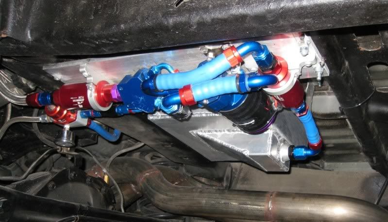
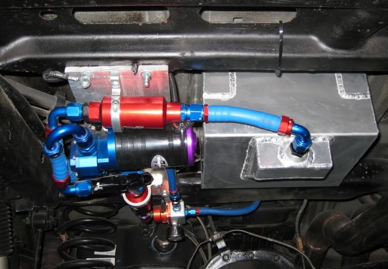
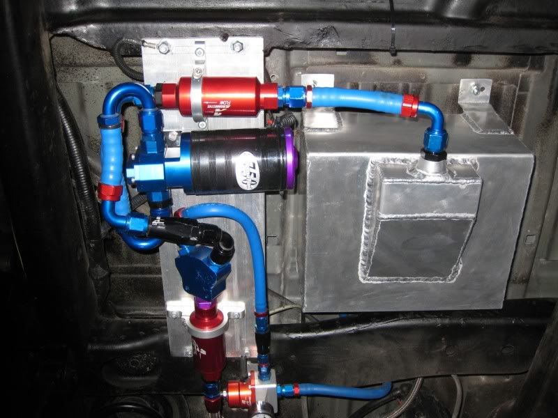
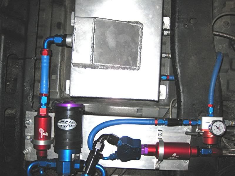
I removed the reg from the OE fuel module and blocked off the port for it. The rear reg is set to factory fuel pressure. I think the front is set to 68 or 70 psi, so it is essentially closed until the Magnafuel kicks in causing the waste from the rear FPR to dump into the surge tank. You could actually run somewhat smaller injectors with this setup because it is a dual pressure system.

Edit: You could do away with the rear reg. I'm not sure how that would affect the factory pump and intank components though. There is a pressure relief port on the OE pumps. Maybe wire it to shut down when the big pump kicks in. This could be a safety feature as well, because if the big pump should fail, there would be no fuel at all and therefore no chance of running lean because only the OE pump was running at WOT.

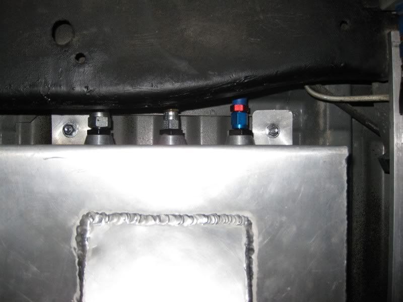
The bungs on the surge tank are actually all at the front near the top, not on the top of the tank as in the drawing (I just cut/pasted the tank from somewhere).

Last edited by DrX; Apr 23, 2011 at 04:21 PM.
Reply
Old Apr 24, 2011 | 02:14 PM
  #55  
DrX's Avatar
DrX
TECH Addict
20 Year Member
iTrader: (7)
 
Joined: Jun 2005
Posts: 2,703
Likes: 6
From: Canada
Default

A few new pics. I cut out the spare tire support to tuck the tank up higher.


Reply
Old Feb 8, 2012 | 04:06 AM
  #56  
caddy03pimpin's Avatar
Launching!
iTrader: (18)
 
Joined: Nov 2008
Posts: 297
Likes: 0
From: socal
Default

Good info here
Reply
Related Topics
Thread
Thread Starter
Forum
Replies
Last Post
Rafe19
FORCED INDUCTION
73
Oct 18, 2016 12:27 AM
Wareagle23
FORCED INDUCTION
8
Aug 15, 2015 06:55 PM
MS3Z
FUEL SYSTEMS
8
Jul 30, 2015 06:17 PM
4B11T
INTERNAL ENGINE MODIFICATIONS
2
Jul 13, 2015 03:48 PM


All times are GMT -5. The time now is 06:43 PM.