
Official A4 to M6 (T-56) Thread!
 May 20, 2012 | 07:04 PM
#1011

Do you know how much of an air gap you have between the sensor and the wheel? I'm guessing you had to space out the sensor a tad? My 4L60E was about 0.02. Mine is a little less right now, probably 0.01". I'm gonna try to space it out a tad.
 May 21, 2012 | 02:14 AM
#1013
Went for a drive tonight and got the cruise to work intermittently. Sometimes I'll turn it on and the CRUISE light will come on for a fraction of a second then turn off, and I can hear a clunk from the cruise control module on the firewall. Most of the time it won't even do that. I got it to stay on once for about 5 seconds before I came to a stop light.
Perhaps its a loose connection or a bad reading from the speed sensor. I'm going to space out a sensor a little more tomorrow and see if that helps, and double check the connector for the cruise control since I was messing with it to wire in the cruise release signal to the clutch switch.
Perhaps its a loose connection or a bad reading from the speed sensor. I'm going to space out a sensor a little more tomorrow and see if that helps, and double check the connector for the cruise control since I was messing with it to wire in the cruise release signal to the clutch switch.
May 21, 2012 | 12:33 PM
#1014
Got it figured out. I think I had a bad pin or two in the CC connector, I was shoving the multimeter probes into the pins and bent them up. I cruised all the way to work this morning and the clutch switch released the cruise perfectly. I will writeup some wiring tips for this thread.
May 21, 2012 | 06:58 PM
#1015
Crap. I spaced out my speed sensor about 0.009" more than before (because it was just barely touching the reluctor wheel) and now the ABS and BRAKE lights come on over 65mph. Cruise still worked, but it was twitchy due due to the bouncy speed readings it was getting. I guess I'll move the sensor back in a little bit.
May 25, 2012 | 06:28 PM
#1016
Here is a writeup on how to do some wiring for this swap. I tried using Quik's diagram I found in this thread and it straight up didn't work, or maybe I did it wrong.
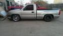
This guide is for 4L60E to T56, on my '01 Silverado 5.3L ECSB. If you have a different vehicle then this might not completely apply. Use this guide at your own risk! Do all wiring with the battery disconnected!
Getting it to start:
When removing the auto trans you will be left with the black plastic box that was on the driver side of the trans. It's called the park neutral position (PNP) switch. If you're like me, the connectors are glued in so you will have to cut the wires, no big deal. The large connector is for the park/neutral position indicator, reverse lights, ground, etc. The smaller connector is for the transmission range switch, which tells the PCM what gear the selector is in.
To get it to start, simply connect the purple/white (starter relay coil supply voltage) wire to the yellow (neutral safety park/neutral signal) wire on the large connector. You should now be able to start the truck. The gear indicator on the dash will read 2ND or blank in run, and 2ND with the engine running. I believe 2ND is some sort of default.
Reverse Lights:
The reverse lights are also easy. There are two green wires on the large PNP connector. The one in pin F is for the reverse lights. Hook this wire and the pink wire to the two wires on the reverse light switch on the T56. It does not matter which wire goes to which. The reverse lights should now come on when the T56 is in reverse with the key in run.
Reverse Lockout Solenoid:
This one is a little more difficult. I believe the f-bodies have the reverse lockout wired into the PCM which controls the solenoid. I wasn't sure if this can be engaged in the tune with a truck PCM, so I wired it to the brake lights instead. When I push on the brakes, the solenoid activates and lets me go into reverse.
There is a cluster of wires that runs along the driver side frame rail all the way to the back of the truck. Inside the cluster you will find several light blue wires. Once of them is for the brake lights. Use a multimeter to find the one that has 12V when the brake is depressed, and 0V when the brake is released. Tap into this wire and run it to one of the reverse lockout wires on the T56. Run the other reverse lockout wire to ground. For ground I used the black/white wire from large connector on the PNP switch.
Speed Sensor:
Plugs right in, dont even have to extend the wires. The speedo will be way off however until you get it tuned. The auto has a 40T wheel, while the T56 has a 17T. I used a 40T wheel in my T56 however and it seems to be working out so far.
Skip Shift Solenoid (CAGS):
F that. Leave it unplugged.
Clutch Switch:
I purchased the 6-pin clutch switch that mounts right onto the master cylinder pushrod. If you have a different one then this may be of less help to you. There are two things we want the clutch switch to do; prevent the truck from starting without the clutch depressed, and disengage the cruise control when the clutch is depressed.
For starting with the clutch depressed, hook the yellow and purple/white wires from the PNP switch to the clutch switch. I used a multimeter and found these wires under the fuse box and tapped into them and ran the wires into the cab and hooked them to the clutch switch. Hook these wires to the two middle pins of the clutch switch. With the clutch depressed, the clutch switch connects these two wires.
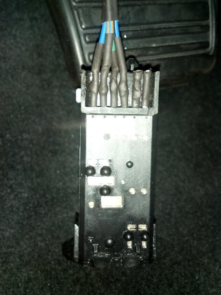
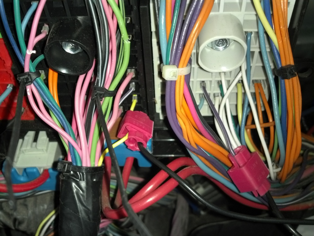
For the cruise control release, you will want to find the purple wire from the brake pedal switch. This wire outputs 12V to the cruise control module unless the brake is depressed, then it outputs 0V. Simply wire the clutch switch into this purple wire between the brake switch and the cruise control module. I cut the purple wire right next to the brake switch. I then hooked both ends of the purple wire to the first two pins of the clutch switch (see picture). I *think* the two pins on either side of the middle two pins will work, but I know the two pictured will work. On mine, the cruise control will release before the clutch itself releases.
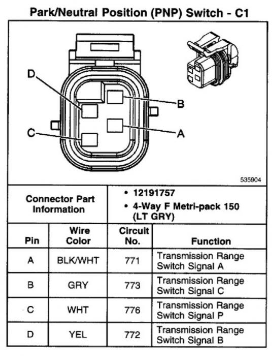
Transmission Range Switch:
This is the smaller 4-pin connector on the PNP switch, and it confused me. According to what I found on LS1tech, if you ground the right range switch wires it will get the dash gear display to show different things. I messed around with it until I got the dash to display DRIVE with the engine off. However, once the engine was running it would go back to 2ND. I left it wired this way, but now it always shows 2ND, engine running or not. As mentioned, I think this is some sort of default. I believe you can just leave the range switch wires not connected to anything. I will be looking into turning off the gear display on the dash soon.
This wiring setup has worked for me so far. Didn't blow any fuses, nothing caught on fire. So far so good!
Disregard the colors of the wires on the clutch switch, they are just scrap wire I had laying around.


This guide is for 4L60E to T56, on my '01 Silverado 5.3L ECSB. If you have a different vehicle then this might not completely apply. Use this guide at your own risk! Do all wiring with the battery disconnected!
Getting it to start:
When removing the auto trans you will be left with the black plastic box that was on the driver side of the trans. It's called the park neutral position (PNP) switch. If you're like me, the connectors are glued in so you will have to cut the wires, no big deal. The large connector is for the park/neutral position indicator, reverse lights, ground, etc. The smaller connector is for the transmission range switch, which tells the PCM what gear the selector is in.
To get it to start, simply connect the purple/white (starter relay coil supply voltage) wire to the yellow (neutral safety park/neutral signal) wire on the large connector. You should now be able to start the truck. The gear indicator on the dash will read 2ND or blank in run, and 2ND with the engine running. I believe 2ND is some sort of default.
Reverse Lights:
The reverse lights are also easy. There are two green wires on the large PNP connector. The one in pin F is for the reverse lights. Hook this wire and the pink wire to the two wires on the reverse light switch on the T56. It does not matter which wire goes to which. The reverse lights should now come on when the T56 is in reverse with the key in run.
Reverse Lockout Solenoid:
This one is a little more difficult. I believe the f-bodies have the reverse lockout wired into the PCM which controls the solenoid. I wasn't sure if this can be engaged in the tune with a truck PCM, so I wired it to the brake lights instead. When I push on the brakes, the solenoid activates and lets me go into reverse.
There is a cluster of wires that runs along the driver side frame rail all the way to the back of the truck. Inside the cluster you will find several light blue wires. Once of them is for the brake lights. Use a multimeter to find the one that has 12V when the brake is depressed, and 0V when the brake is released. Tap into this wire and run it to one of the reverse lockout wires on the T56. Run the other reverse lockout wire to ground. For ground I used the black/white wire from large connector on the PNP switch.
Speed Sensor:
Plugs right in, dont even have to extend the wires. The speedo will be way off however until you get it tuned. The auto has a 40T wheel, while the T56 has a 17T. I used a 40T wheel in my T56 however and it seems to be working out so far.
Skip Shift Solenoid (CAGS):
F that. Leave it unplugged.
Clutch Switch:
I purchased the 6-pin clutch switch that mounts right onto the master cylinder pushrod. If you have a different one then this may be of less help to you. There are two things we want the clutch switch to do; prevent the truck from starting without the clutch depressed, and disengage the cruise control when the clutch is depressed.
For starting with the clutch depressed, hook the yellow and purple/white wires from the PNP switch to the clutch switch. I used a multimeter and found these wires under the fuse box and tapped into them and ran the wires into the cab and hooked them to the clutch switch. Hook these wires to the two middle pins of the clutch switch. With the clutch depressed, the clutch switch connects these two wires.
For the cruise control release, you will want to find the purple wire from the brake pedal switch. This wire outputs 12V to the cruise control module unless the brake is depressed, then it outputs 0V. Simply wire the clutch switch into this purple wire between the brake switch and the cruise control module. I cut the purple wire right next to the brake switch. I then hooked both ends of the purple wire to the first two pins of the clutch switch (see picture). I *think* the two pins on either side of the middle two pins will work, but I know the two pictured will work. On mine, the cruise control will release before the clutch itself releases.
Transmission Range Switch:
This is the smaller 4-pin connector on the PNP switch, and it confused me. According to what I found on LS1tech, if you ground the right range switch wires it will get the dash gear display to show different things. I messed around with it until I got the dash to display DRIVE with the engine off. However, once the engine was running it would go back to 2ND. I left it wired this way, but now it always shows 2ND, engine running or not. As mentioned, I think this is some sort of default. I believe you can just leave the range switch wires not connected to anything. I will be looking into turning off the gear display on the dash soon.
This wiring setup has worked for me so far. Didn't blow any fuses, nothing caught on fire. So far so good!
Disregard the colors of the wires on the clutch switch, they are just scrap wire I had laying around.
Last edited by Ferocity02; Sep 21, 2012 at 02:10 PM.
Jun 7, 2012 | 12:14 PM
#1017
Does anyone know what the deal with a 2006 and doing this swap? I saw somewhere in this thread that the 06 had a couple things that are different but it didn't go into detail about it. I am planning on doing this to my 06 SS.
Jul 15, 2012 | 12:15 AM
#1018
On The Tree
Joined: Apr 2012
Posts: 199
Likes: 0
From: ohio
ok guys im in the process of doing the swap. just got done doing the pedals and it kicked my *** anyways there is some kinf of sensor on the brake pedal and then a clip that holds the boster rod to the pedal ans was wondering if someone cold take a pick of it cause i cant remember how it goes.
Sep 21, 2012 | 09:08 AM
#1019

On my 03' SS the wire colors were a little different on the trans range switch
Pin E - Pink - Tied to Ign E fuse 10A
Pin G - Dark Green
Pin C - Pink - Tied to B/U LP fuse 20A
Pin F - Grey
Also FWIW I had to cut the torsion bar mount in half to get my tcase to fit
Pin E - Pink - Tied to Ign E fuse 10A
Pin G - Dark Green
Pin C - Pink - Tied to B/U LP fuse 20A
Pin F - Grey
Also FWIW I had to cut the torsion bar mount in half to get my tcase to fit
Sep 27, 2012 | 10:00 PM
#1020
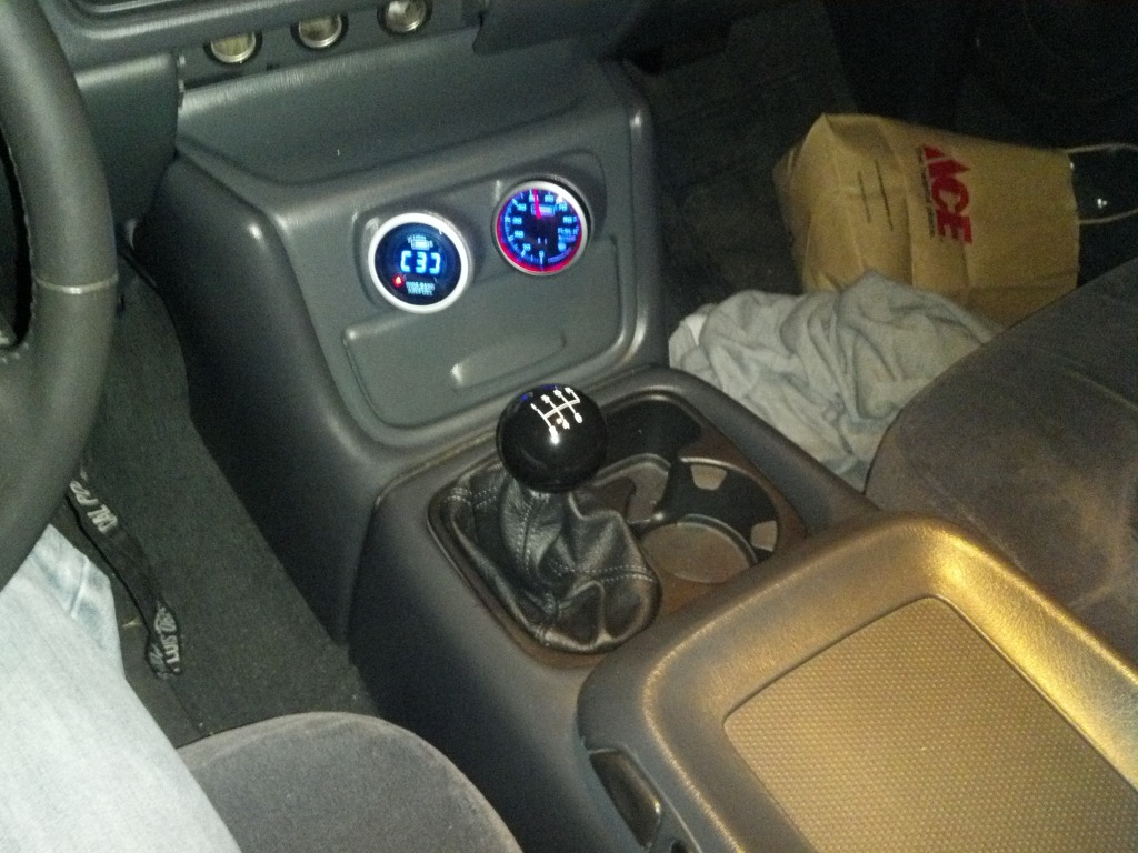
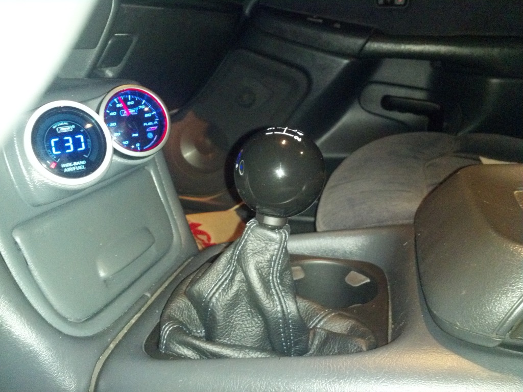
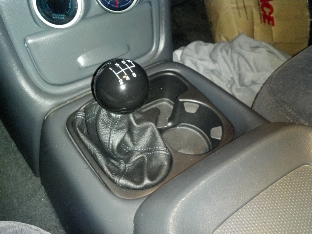
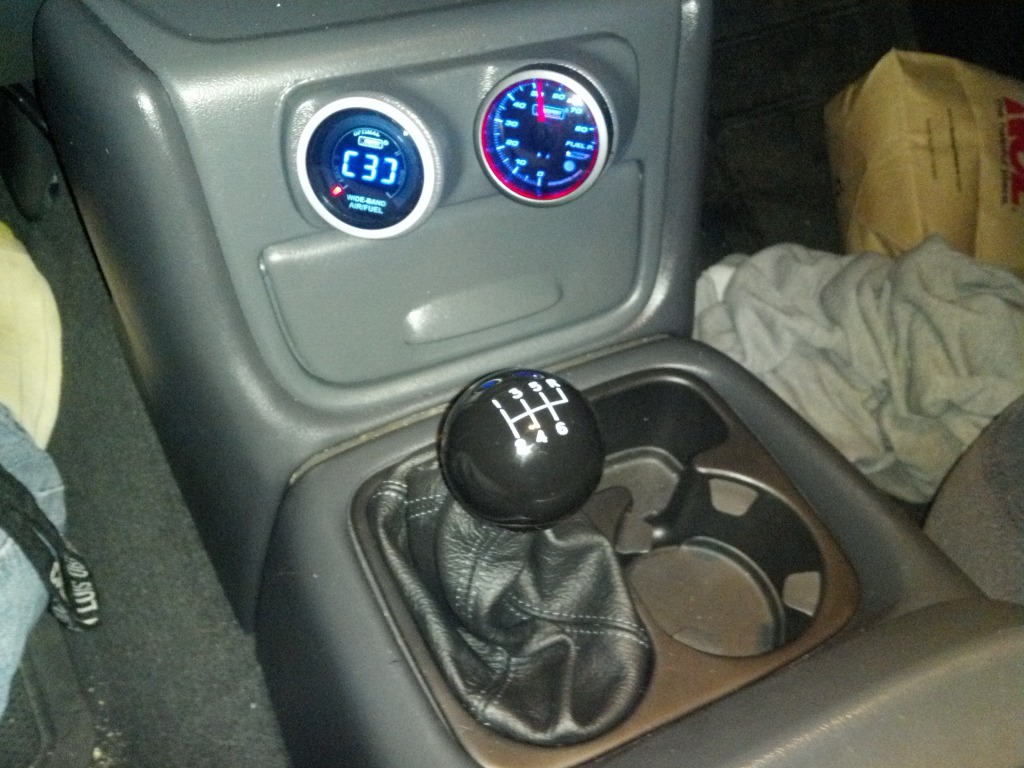
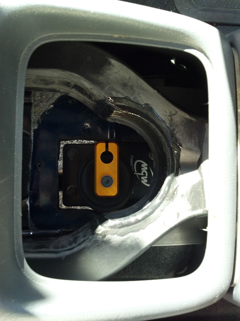
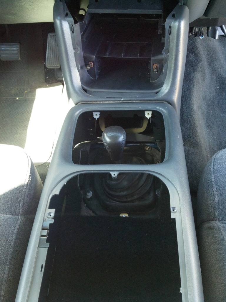
FINALLY got my shifter done... It was a pain in the *** with the 99-02 console. An 03-06 console will give you a LOT more room for the shifter to move about, and you can keep two cup holders on the right side instead of one. But I couldn't find a good 03-06 console for a decent price, and I wanted to keep my rear HVAC. If the throws were any greater there would not be enough room. If I shift hard enough, I'll hit the left side going into first, the back going into 2nd, the front going into 1st and 3rd, and the right going into reverse. If I am gentle to moderate it won't hit at all.
I cut up the cup holder and glued in some plastic bits to make a new center wall. And lots of epoxy, bondo, sanding, and painting it was done.
The boot I got from Redline Goods out of Norway. They made me a custom boot for $100 after I gave them all of the dimensions they needed. Very high quality product. I bend up a metal retaining ring from strip aluminum to hold the boot in place. The ring bolts to inside of the cup holder securing the boot in place.
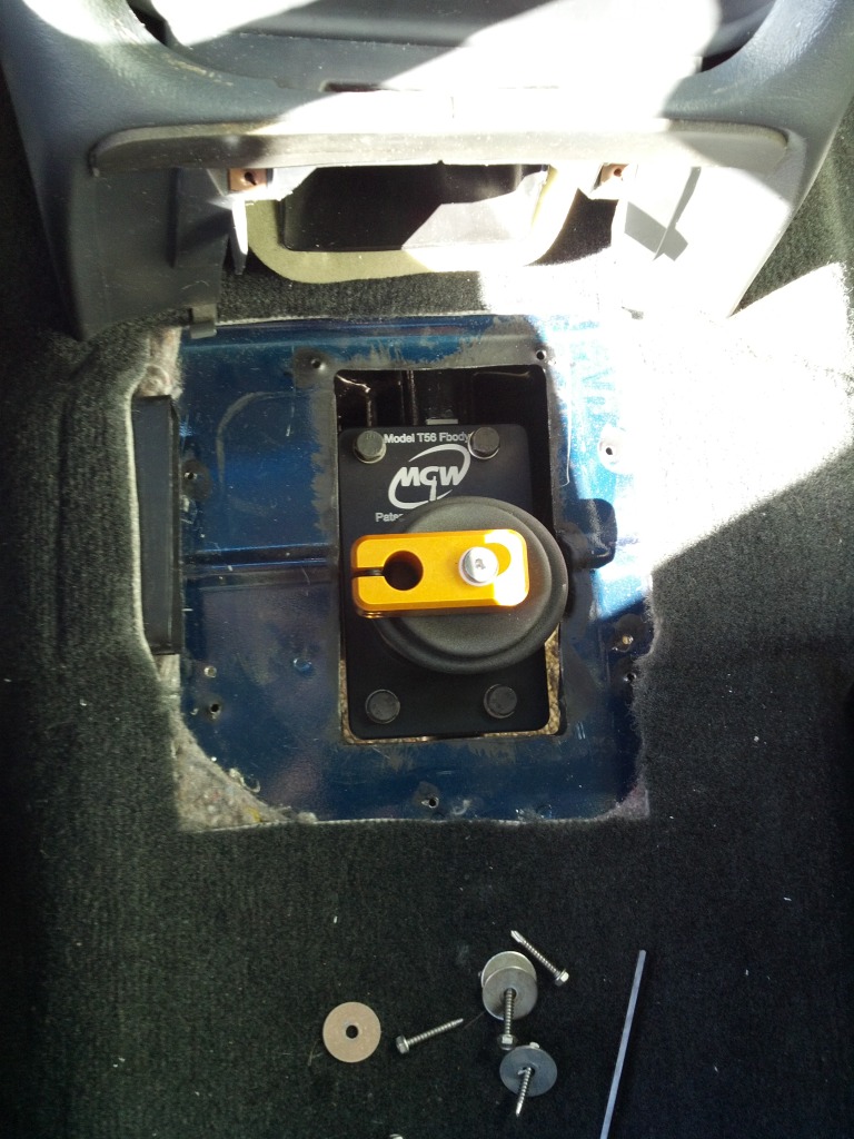
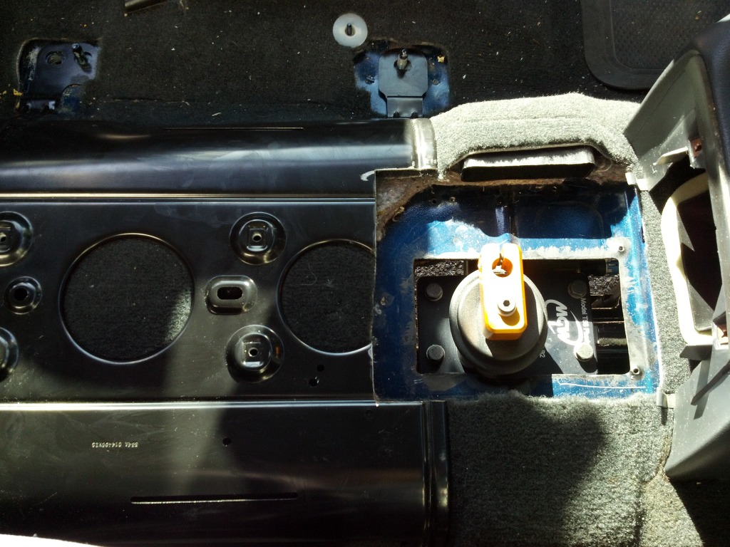
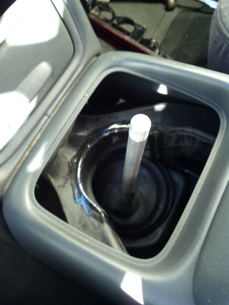
I used an MGW shifter for the shortest possible throws. Bent up my own 5/8" steel shifter shaft. Had to do some cutting of the metal console base mount and the rear bottom driver side HVAC duct. I cut out a section of the rear upper HVAC duct to make room for the shifter and glued in a piece of 4" PVC.
My first shifter shaft was a straight section of 5/8" aluminum rod, shown in the pics below. I could have used this but would have lost the entire cupholder. I don't have pics of the new rod I bent from steel.
I cut up the cup holder and glued in some plastic bits to make a new center wall. And lots of epoxy, bondo, sanding, and painting it was done.
The boot I got from Redline Goods out of Norway. They made me a custom boot for $100 after I gave them all of the dimensions they needed. Very high quality product. I bend up a metal retaining ring from strip aluminum to hold the boot in place. The ring bolts to inside of the cup holder securing the boot in place.
I used an MGW shifter for the shortest possible throws. Bent up my own 5/8" steel shifter shaft. Had to do some cutting of the metal console base mount and the rear bottom driver side HVAC duct. I cut out a section of the rear upper HVAC duct to make room for the shifter and glued in a piece of 4" PVC.
My first shifter shaft was a straight section of 5/8" aluminum rod, shown in the pics below. I could have used this but would have lost the entire cupholder. I don't have pics of the new rod I bent from steel.