Finish Line Transmissions 4l60e Build Up Thread
 12-30-2007, 06:30 PM
#21
formerly 1BADC10 (12/14/2011)
iTrader: (2)

Join Date: Aug 2005
Location: TX
Posts: 2,135
Likes: 0
Received 0 Likes
on
0 Posts
You guys... that's f'd up. My trans has been taking punishment pretty well this month. The converter will soon be swapped for a Yank. That'll be done next month. Should have it ordered in the next couple of weeks. Yup... trans will be pulled back once more, but I won't have to dig into it. 
*edit*
That plan changed... Have a couple other things on order first. Maybe the TC when my annual money tree grows in a couple months. 
*edit*
That plan changed...
Last edited by 95ImpSS; 01-08-2008 at 11:20 AM.
 01-07-2008, 07:23 AM
#22
In this next portion of the thread we will be installing the clutches in the input drum. We left off in post #11 with the internal pistons being installed along with the modified spring cages. Here is a picture as to where I left off.

The first things to do now are to install the input drum to sprag bearing and put a little assembly lube on the seal for the lube circuit connecting the input drum to the output shaft. Here are some photo's.


Now it is time to install the overrun clutches, steels and also the backing plate which also acts as the apply plate for the forward clutch. The line up of these parts will start with a steel, clutch, steel, clutch and then the backing plate. Here is the line up of these parts outside of the drum.

This first picture has the first overrun steel installed.

Then we will install the first clutch and repeat the process.


And then finish up with the backing plate.

At this point the wave plate can be installed for the forward clutch. This plate is designed the way it is to absorb some of the shock of the apply of the forward clutch. Here are a couple photo's of it.

And one with it installed in the drum.

Next we will get our input sprag assembly together. It will have have the sun gear for the front planet with the bushing already installed. The sprag race surfaces carefully inspected to be in good condition. The sun gear will also be inspected for pitting or abnormal wear. If any of these pieces do not meet our criteria they are replaced. A new Borg Warner sprag is also installed at this point and time. Here are a few photo's of the assembly as it goes together.


Also once all the pieces are installed and the snap ring that keeps it together is in place, I will lube the bushings.

Now the sprag assembly is complete and can be installed in the drum.

The next step will be to get the forward clutch assembly ready and installed.
The first things to do now are to install the input drum to sprag bearing and put a little assembly lube on the seal for the lube circuit connecting the input drum to the output shaft. Here are some photo's.
Now it is time to install the overrun clutches, steels and also the backing plate which also acts as the apply plate for the forward clutch. The line up of these parts will start with a steel, clutch, steel, clutch and then the backing plate. Here is the line up of these parts outside of the drum.
This first picture has the first overrun steel installed.
Then we will install the first clutch and repeat the process.
And then finish up with the backing plate.
At this point the wave plate can be installed for the forward clutch. This plate is designed the way it is to absorb some of the shock of the apply of the forward clutch. Here are a couple photo's of it.
And one with it installed in the drum.
Next we will get our input sprag assembly together. It will have have the sun gear for the front planet with the bushing already installed. The sprag race surfaces carefully inspected to be in good condition. The sun gear will also be inspected for pitting or abnormal wear. If any of these pieces do not meet our criteria they are replaced. A new Borg Warner sprag is also installed at this point and time. Here are a few photo's of the assembly as it goes together.
Also once all the pieces are installed and the snap ring that keeps it together is in place, I will lube the bushings.
Now the sprag assembly is complete and can be installed in the drum.
The next step will be to get the forward clutch assembly ready and installed.
01-07-2008, 07:25 AM
#23
As I left off in the above post it is time to get the forward clutch assembly ready to be installed. Note that 5 frictions, 5 steels, a new pressure plate installed for adjusting clutch clearance, and the snap ring that keeps everything in place here in this photo.

Here is a line up of this assembly.


The first step is to install the first forward steel. This is much like any other clutch pack as it will alternate from a steel to a clutch and end up with the pressure plate. Here is a picture with the steel in the drum.

Then a clutch will be installed and the the process will be repeated until all 5 steel and clutch plates are installed. Here are the photo's.


Then the forward clutch pressure plate will be installed. We do use different thickness plates from GM to achieve the proper FLT clutch clearance for this clutch. Here are the photo's of it being installed and also the snap ring that is used to retain these parts.


The next step will be to install the 3-4 clutch pack assembly. At FLT we use an 8 pack clutch set up with Coleen steels. All of these pieces are replaced with new parts in every new unit that we assemble. This includes both the apply plate, pressure plate, frictions and the steels. Here are a couple photo's of the parts used and also the line up of the parts.


Next we will install the 3-4 clutch assembly.
Here is a line up of this assembly.
The first step is to install the first forward steel. This is much like any other clutch pack as it will alternate from a steel to a clutch and end up with the pressure plate. Here is a picture with the steel in the drum.
Then a clutch will be installed and the the process will be repeated until all 5 steel and clutch plates are installed. Here are the photo's.
Then the forward clutch pressure plate will be installed. We do use different thickness plates from GM to achieve the proper FLT clutch clearance for this clutch. Here are the photo's of it being installed and also the snap ring that is used to retain these parts.
The next step will be to install the 3-4 clutch pack assembly. At FLT we use an 8 pack clutch set up with Coleen steels. All of these pieces are replaced with new parts in every new unit that we assemble. This includes both the apply plate, pressure plate, frictions and the steels. Here are a couple photo's of the parts used and also the line up of the parts.
Next we will install the 3-4 clutch assembly.
01-07-2008, 07:26 AM
#24
Here is another picture of the 3-4 clutch assembly ready to be installed in the drum.

The first plate to be installed is the new 3-4 apply plate. Here are a couple photo's of it being installed.


Next we will install the clutches and steels. Once again it will start with a clutch followed by a steel until all 8 frictions are installed along with 7 steels. Here are the photo's.


Now it is time to install the new pressure plate. These plates come in different thicknesses to adjust the 3-4 clutch clearance. You can also tighten this pack up by the use of thicker frictions. Some guy's will use different thickness steel plates or snap rings but I like to do it with frictions and pressure plates. Here is a photo of the pressure plate being installed along with the snap ring.


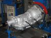
The drum is now complete. It is a good practice to check the clutch clearances with the use of feeler gauges after air checking the drum. Air checking the drum will seat the clutch pack and the snap ring in the drum. This will give us the most accurate measurement. Also while air checking the drum it will verify if there are any leaks in the drum and the seals of it. Here is a picture of the drum fully assembled ready to be installed in the trans. Also a one of the trans without the drum and one with it in the trans.


In the next segment I will be assembling the reverse input drum and it's assemblies. Also I will show you the way I check my end play of the transmission before these assemblies are installed. Stay tuned and feel free to ask any technical questions. Enjoy the thread. Vince
The first plate to be installed is the new 3-4 apply plate. Here are a couple photo's of it being installed.
Next we will install the clutches and steels. Once again it will start with a clutch followed by a steel until all 8 frictions are installed along with 7 steels. Here are the photo's.
Now it is time to install the new pressure plate. These plates come in different thicknesses to adjust the 3-4 clutch clearance. You can also tighten this pack up by the use of thicker frictions. Some guy's will use different thickness steel plates or snap rings but I like to do it with frictions and pressure plates. Here is a photo of the pressure plate being installed along with the snap ring.
The drum is now complete. It is a good practice to check the clutch clearances with the use of feeler gauges after air checking the drum. Air checking the drum will seat the clutch pack and the snap ring in the drum. This will give us the most accurate measurement. Also while air checking the drum it will verify if there are any leaks in the drum and the seals of it. Here is a picture of the drum fully assembled ready to be installed in the trans. Also a one of the trans without the drum and one with it in the trans.
In the next segment I will be assembling the reverse input drum and it's assemblies. Also I will show you the way I check my end play of the transmission before these assemblies are installed. Stay tuned and feel free to ask any technical questions. Enjoy the thread. Vince


 01-27-2008, 11:30 PM
#29
In post 24 I left off with the input drum fully assembled and installed in the transmission. The next step will be to get the reverse input drum ready to be installed in the trans. Here is where we left off.
Here is a photo of the reverse input drum.

This is a piece that is used for more than one purpose. Not only do the clutches inside the drum get applied when the trans shift selector is placed in reverse, but the outside of the drum is used to apply the 2-4 band. With that being said it also is used for 2nd and 4th gears. Here is the photo of a new drum that we use in almost every unit that we build. Also here are the internal components and the band that this drum uses.

The only time I will reuse this drum is when it is totally perfect which is very rare for a used 4l60e. Most companies will reuse these even though they have signs of ware. The band surface warps. The lugs where the sun shell splines together wares. Also the area where the apply cushion plate rides wares out. This will cause damage to the input drum from it being allowed to rub due to more travel side to side in the reverse input drum. Also I have seen where it can cause the reverse input piston to bind on the apply. Causing a delayed engagement in reverse or a strange double bump apply. A used drum when in good condition should have the bushings replaced and also have the band surface resurfaced. I have seen many attempts of the outside to be resurface by hand sanding or sanding discs on a die grinder. I prefer to use a lathe to resurface the drum. I will use sandpaper by hand to resurface it while the drum spins on the lathe. Then finish it off by polishing it with scotch bright. When I'm done it looks very close to the one in the picture above. It will then be checked to verify that it is flat and smooth.
Once the drum is clean and ready to be assembled the first step is to get the seals installed. Here are a couple photo's.


Next it is a good practise to lube the seals with assembly lube or use a seal lubricate stick to do so. I like to use the seal lubricate stick but it is just builder preference. Here is a photo of the piston lubed and ready to be installed.

The next it is time to install the reverse input piston. Here are a few photo's.

I like to use a long feeler gauge to help install the piston. This will help to not damage the seals.


Once it is all the way down it is time to install the spring cage and it's snap ring. Here are a few photo's of how it's done.


Next we install the reverse input clutches.
Here is a photo of the reverse input drum.
This is a piece that is used for more than one purpose. Not only do the clutches inside the drum get applied when the trans shift selector is placed in reverse, but the outside of the drum is used to apply the 2-4 band. With that being said it also is used for 2nd and 4th gears. Here is the photo of a new drum that we use in almost every unit that we build. Also here are the internal components and the band that this drum uses.
The only time I will reuse this drum is when it is totally perfect which is very rare for a used 4l60e. Most companies will reuse these even though they have signs of ware. The band surface warps. The lugs where the sun shell splines together wares. Also the area where the apply cushion plate rides wares out. This will cause damage to the input drum from it being allowed to rub due to more travel side to side in the reverse input drum. Also I have seen where it can cause the reverse input piston to bind on the apply. Causing a delayed engagement in reverse or a strange double bump apply. A used drum when in good condition should have the bushings replaced and also have the band surface resurfaced. I have seen many attempts of the outside to be resurface by hand sanding or sanding discs on a die grinder. I prefer to use a lathe to resurface the drum. I will use sandpaper by hand to resurface it while the drum spins on the lathe. Then finish it off by polishing it with scotch bright. When I'm done it looks very close to the one in the picture above. It will then be checked to verify that it is flat and smooth.
Once the drum is clean and ready to be assembled the first step is to get the seals installed. Here are a couple photo's.
Next it is a good practise to lube the seals with assembly lube or use a seal lubricate stick to do so. I like to use the seal lubricate stick but it is just builder preference. Here is a photo of the piston lubed and ready to be installed.
The next it is time to install the reverse input piston. Here are a few photo's.
I like to use a long feeler gauge to help install the piston. This will help to not damage the seals.
Once it is all the way down it is time to install the spring cage and it's snap ring. Here are a few photo's of how it's done.
Next we install the reverse input clutches.
01-28-2008, 07:01 AM
#30
Next we install the clutch pack for the reverse input clutch. The first plate to be installed will be cushion plate. It will be installed cone side up. Here are the photo's.


Next is to install the first steel. This will be followed up with by clutch and then repeated until all four steels and four clutches have been installed. Here are the photo's.


The next step is to install the pressure plate and the snap ring. Here are the photo's.


In the next set of photo's I will show how I preset my end play by using the pump stator. Also I will cover the machine process of our pumps along with the assembly of the pump. Enjoy the photo's and stay tuned. More to come. Vince
Next is to install the first steel. This will be followed up with by clutch and then repeated until all four steels and four clutches have been installed. Here are the photo's.
The next step is to install the pressure plate and the snap ring. Here are the photo's.
In the next set of photo's I will show how I preset my end play by using the pump stator. Also I will cover the machine process of our pumps along with the assembly of the pump. Enjoy the photo's and stay tuned. More to come. Vince