


07 NNBS Pinion Angle Issues After Drop
 May 7, 2013 | 10:21 PM
#1

Thread Starter
TECH Regular
Joined: Sep 2007
Posts: 461
Likes: 0
From: Claremont, ON Canada
 07 NNBS Pinion Angle Issues After Drop
Here's my situation, I have a 2007 Sierra NNBS 4x4 Z71, I lowered it using Belltech kit#647SP using the directions I set it to 3" front and 5" rear, came out to more like 2/4 not sure if it's because mine is a Z71?
Anyways, I was getting the 60-70mph "shudder" on the HWY, read a bunch of threads on drive shaft and pinion angles and decided to check things out tonight. I put the font on jack stands, put jack stands under the rear leafs and tried to get the truck to sit as level as possible.
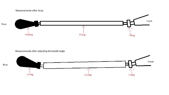
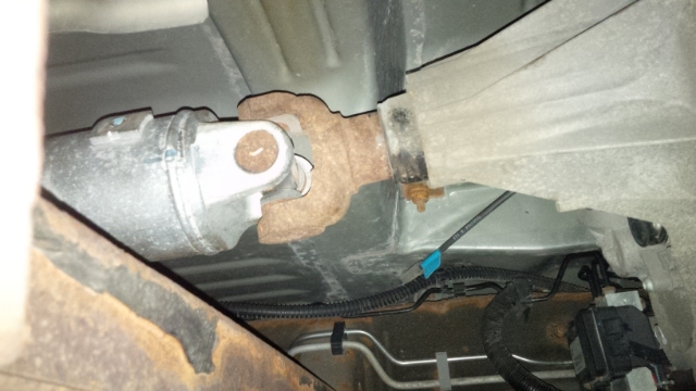
Below you will see where I started off, basically the rear diff was +10Deg and drive shaft was 0Deg. I tried to install the transfer case spacers as per the kit but it actually didn't make a difference at all, so I removed them.
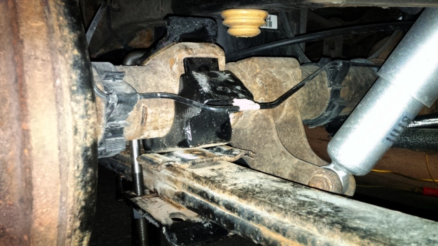
What I did after was use some pieces of metal to "wedge" the drive shaft to a more downward angle, you will see this in the pics below as well. When I life the rear part of the axle saddle 3/4in (which seems like a lot) I then get a diff angle of -3Deg and drive shaft angle of +2Deg.
One thing to note was that the axle yoke that goes inside the transfer case did not change length at all during any of these modifications, kinda odd.
Pics: (This is what a 2007 looks like when you live in Toronto, nice and rusty :S )
Before and after I did in MS Paint, I suck at that program as you can see.
Here you can see what I used to wedge, of course I am not driving the truck like this, it was just for measurement purposes.
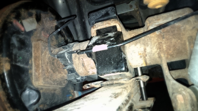
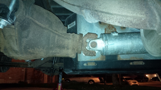
This is what the Rear Diff and Transfer Case look like, kinda of hard to get pics straight on.
Questions I have are:
-Does this look right to you?
-Is needing a 3/4 inch spacer too much? I'm not sure how thick the 6deg spacers are
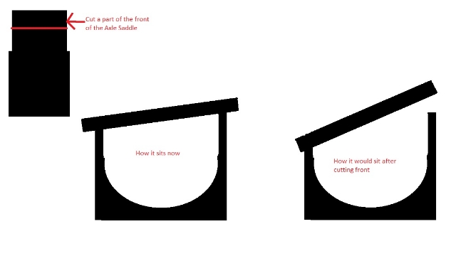
One thing I thought of doing was just modding the axle saddle, if I were to cut some off the front I could rotate the shaft forward, only thing then is the rear wouldn't sit up against the axle pad anymore, not sure if this would cause problems? I would tighten the front first so the axle pad sits on the axle saddle then tighten the rear.
I know I couldn't just remove 3/4" off the front as the axle would be rotating in the saddle rather than what I did here which is lift the rear but if I took a bit off at a time it might work, thoughts?
Another MS Paint explanation:
Appreciate any suggestion, I called a bunch of local mechanics, axle shops, spring shops and no one does this kind of thing.
Jay
Anyways, I was getting the 60-70mph "shudder" on the HWY, read a bunch of threads on drive shaft and pinion angles and decided to check things out tonight. I put the font on jack stands, put jack stands under the rear leafs and tried to get the truck to sit as level as possible.
Below you will see where I started off, basically the rear diff was +10Deg and drive shaft was 0Deg. I tried to install the transfer case spacers as per the kit but it actually didn't make a difference at all, so I removed them.
What I did after was use some pieces of metal to "wedge" the drive shaft to a more downward angle, you will see this in the pics below as well. When I life the rear part of the axle saddle 3/4in (which seems like a lot) I then get a diff angle of -3Deg and drive shaft angle of +2Deg.
One thing to note was that the axle yoke that goes inside the transfer case did not change length at all during any of these modifications, kinda odd.
Pics: (This is what a 2007 looks like when you live in Toronto, nice and rusty :S )
Before and after I did in MS Paint, I suck at that program as you can see.

Here you can see what I used to wedge, of course I am not driving the truck like this, it was just for measurement purposes.


This is what the Rear Diff and Transfer Case look like, kinda of hard to get pics straight on.


Questions I have are:
-Does this look right to you?
-Is needing a 3/4 inch spacer too much? I'm not sure how thick the 6deg spacers are
One thing I thought of doing was just modding the axle saddle, if I were to cut some off the front I could rotate the shaft forward, only thing then is the rear wouldn't sit up against the axle pad anymore, not sure if this would cause problems? I would tighten the front first so the axle pad sits on the axle saddle then tighten the rear.
I know I couldn't just remove 3/4" off the front as the axle would be rotating in the saddle rather than what I did here which is lift the rear but if I took a bit off at a time it might work, thoughts?
Another MS Paint explanation:

Appreciate any suggestion, I called a bunch of local mechanics, axle shops, spring shops and no one does this kind of thing.
Jay
May 7, 2013 | 11:29 PM
#2
Thread Starter
TECH Regular
Joined: Sep 2007
Posts: 461
Likes: 0
From: Claremont, ON Canada
I did more reading and some articles suggest I should get the transfer case angle and rear diff angle to be opposites and cancel each other out, so my transfer case Is -7 deg the rear end should be +7 deg so if that were the case I would just need a 3deg wedge to get it to +7. what do you guys think about that?
I don't want to do too much since I'm going to put the 4L80E in which will move the tcase rear ward and i can really set the angles right when i get a new drive shaft however we will be putting the turbo on with the stock 4L60E first to see what the numbers are so I would like for it to run as good and safe as possible.
I don't want to do too much since I'm going to put the 4L80E in which will move the tcase rear ward and i can really set the angles right when i get a new drive shaft however we will be putting the turbo on with the stock 4L60E first to see what the numbers are so I would like for it to run as good and safe as possible.
May 8, 2013 | 01:59 PM
#3

TECH Enthusiast

Joined: Feb 2008
Posts: 628
Likes: 1
From: Salt Lake City
If you have a one piece shaft you want the angles to cancel each other. If your above illustrations is a correct "before" representation, you have the t case 7* down. Consider that a fixed point/measurement. Your diff is 10* up, so you need to bring the pinion down 3*. However, under power the pinion will want to climb, so I usually set them down 1-2*. A 4* shim, installed so it pitches the pinion down will set you up correctly. You are gonna want a steel shim, not an aluminum or cast shim. Much stronger and safer. And new center pins.
Something like this
http://www.amazon.com/gp/aw/d/B004JARX70
Something like this
http://www.amazon.com/gp/aw/d/B004JARX70


Thread
Thread Starter
Forum
Replies
Last Post
zblee
GM Engine & Exhaust Performance
63
Jun 10, 2023 01:25 PM
Noah Burns
GMT K2xx Trucks General Discussion
5
Sep 7, 2015 05:50 PM
Dezert1500
GM Parts Classifieds
5
Jul 30, 2015 02:51 PM


