
PCV Catch Can Setup
 Apr 16, 2012 | 02:27 PM
#31
 Apr 16, 2012 | 03:36 PM
#32

 Apr 17, 2012 | 09:07 PM
#33

I wouldn't run anything to in front of the turbo or supercharger without a catch can in-line. I don't get the whole clean side, dirty side thing, you'll get blowby from every location or in the case of a turbo or supercharger it'll suck the oil right out of the valve cover. The dual catch can setup seems to be the best way.
Thanks to 405HP_Z06 for the diarams!
Apr 17, 2012 | 09:18 PM
#34

Well I got my setup done. I read a few threads about the "Ford turbo coupe PCV" (PN E5ZZ-6A666-A) and how it could just replace the truck PCV valve and also work as a 1 way check valve. I tried the the Mcmaster (PN 7775K52) but the cracking point was too high.


And this is my new setup. We'll see how it holds up
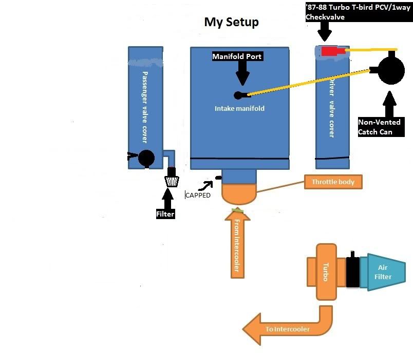
And this is my new setup. We'll see how it holds up
Apr 18, 2012 | 12:53 AM
#35

I asked this before, but do we have to worry about unmetered air entering through the breather, passing through the engine, then getting sucked into the intake manifold and burned? Or is there enough blowby to counteract this?
Apr 18, 2012 | 09:04 AM
#36
His was an orifice style so it would definitely allow air to go both ways, from what I have seen of regular pcv's they wouldnt seal perfectly when going in the opposite direction, cool find on that motorcraft part that works as a check valve as well, will save me much complication. Hopefully it is roughly the same flow rate.
The amount of flow going through the line should already be compensated for as you tune, unless you unhook the line or plug it, it shouldn't affect anything.
The amount of flow going through the line should already be compensated for as you tune, unless you unhook the line or plug it, it shouldn't affect anything.

 Apr 20, 2012 | 09:09 AM
#38

Teching In
Joined: Apr 2012
Posts: 21
Likes: 0
Hi all,
I was asked to come in and shed some light on this mostmisunderstood system and try to lend some clarity.
Below I will (and this will be long, but please read ALL so you understand all the aspects of doing this right) post several papers on this subject. This will deal with both NA and FI applications.
We will start with the basics:
Understanding the evolution of the LS series
crankcase ventilation system
I'll address GM's path to improving the oil ingestion issue, but the trade off is less effective crankcase evacuation. The goal of balancing proper evac with ever stricter EPA emission rules makes this a trade-off.
First with the introduction of the GenIII LS1 in 1997. The crankcase evac route was drawing it from both valve covers at the rear of each with the fresh make up air drawn from the top of a tube on the throttle body. This allowed a great deal of oil intrusion from both the valve covers & through reversion into the TB in front of the blade.
The next revision came with the LS6 and the valley cover. This helped some with the oil ingestion, but the trade-off was a far less effective crankcase evac as the drivers side valve train got virtually no flow through to flush & evac the harmful combustion byproducts, and the early valley covers allowed to much oil to be drawn out with the gasses. Enter the LS2 and a redesigned valley cover with a baffle system. This worked quite well and minor changes to the newer releases helped as well. Leaving us with the same issue of the drivers side valvetrain not being flushed properly, but the 90mm TB had the fresh air tube eliminated and the make-up air drawn from the intake air bridge. This still allows some ingestion at WOT when the intake manifold vacuum is at its lowest. The L99 then went to drawing from rear of the drivers side valve cover and a still further improved baffle in the valve cover. This solution at least allows proper flushing on both banks and the crankcase itself. Picture the fresh air entering the front of the passenger side valve cover, flowing around the rocker arms, down the pushrod valley, through the crankcase, up the drivers side pushrod valley, around the rocker arms, and exiting the rear of the drivers side valve cover and pulling (flushing) the harmful combustion byproducts out. The problem is the flow is limited and the evacuation still inadequate. When allowed to flow at an effective rate the oil ingestion rises and the problems caused (listed in the earlier posts) are still an issue.
Also, the LS3 STILL pulls from the valley cover which is not all bad except the fixed orifice is to restrictive to allow proper flow.
Now on to the catchcans on the market.
First are the Home Depot/Lowes plastic air compressor separators. These will catch oil, but due to the extremely small size they cannot prevent the majority of oil being pulled through. Take a drinking straw and put a teaspoon full of water in your mouth. Blow it out and almost all is forced through the straw and out. Same with oil. The velocity, or the speed of the flow carries any liquid with it. Now do the same through a piece of garden hose. You will have a hard time getting much at all to force out (as long as you don't tip it down and let gravity help). This is due to the velocity of the flow. measured, the flow may be the same when measured at the inlet & outlet of either, but the internal volume of the hose is much greater than the straw so the velocity slows enough for the droplets to settle and not be puled, or forced through where the straw blows it right out.
Same with a catchcan. The smaller the internal volume, the less effective it can be no matter what the filtering or other internal design. It is simple physics.
Next, most have a mesh filter media inside. This works well at first, but soon becomes saturated and then as the droplets fall to collect in the bottom for removal, the outlets are maybe 1/2-1" from the media so many of the smaller droplets are pulled right out the outlet and into the intake manifold. These can be modified with a simple deflector to help prevent much of it, but the small size still allows the flow to speed through to fast for all the oil to drop out of suspension.
Then there comes the larger liquid overflow cans with 2 fittings added but are empty inside with little to no baffling. These catch a good amount of oil due to the slowing of the flow, but 20-30% of the oil still flows right through as it takes the path of least resistance.
The best cans have a large capacity (near 1 qt or more), a way to evenly disperse the vapors as they flow through so they make as much contact with the cooling surfaces to condense the vapor/mist to droplets. Then the inlet & outlet must be as far apart as possible to prevent pull-through. Out of the cans on the market, we have tested most everyone we come across and after testing (run on the same car for the same drive with the same type of driving with a clear glass inline fuel filter plumbed between the can outlet and the intake manifold vacuum fitting. This shows the amount of oil pull-through) we cut the cans lengthwise on a band saw to examine the entire makeup of the can. We found the air compressor type plastic units only catch app 40% of the oil. Next the smaller billet cans had quite a bit of variance with say the smaller billets catching 80% or so, but the near identical looking Billet cans (a few different names) only caught maybe 50-60%. Dissection quickly showed the can had the inlet entering a separate filter media chamber and the outlet drew from the containment portion so that separation made a huge difference where the billet units have the inlet & outlet in the same small chamber the filter media is in so it was pretty obvious.
Then only 2 come in allowing almost NO or NO detectable oil through. The Saikou Micchi (excuse my spelling) which as a center perforated dispersion tube running down the middle and the outlet app 6-7" away at the top of the can. This works awesome but they have added filter media in the past year and we see some oil pull through now that wasn't coming through before the media. This we attribute to the oil saturated media allowing droplets to pull through. And the RX Performance Products.
And further next post:
Apr 20, 2012 | 09:11 AM
#39
Teching In
Joined: Apr 2012
Posts: 21
Likes: 0
Understanding oil contamination from combustion byproducts
The evac system is not for the environment....it is to keep the engine alive and wear free as long as possible. Your not alone and 99% of car owners never think about it or realize whats happening over time. And yes, most will drive 50-75-100k plus miles and never know the damage gradually being done.
My qualifications?
over 35 years building race and performance engines.
Mechanical & Automotive engineer by trade
Graduate of the Reher Morrison Racing engine building school (one of the most respected in the world and a GM R&D contractor).
Owner and driver of drag teams with multiple Divisional, National & World championships in both NHRA & IHRA in several classes (this is where every minute detail in an engine matters)
And I tear down and build most every kind/brand of motor imaginable (except diesel) on a weekly basis.
So here goes:
Every motor has a certain amount of blow-by, the bigger the CI & the more boost the more blow-by (with everything else assumed is equal and no piston/ring/cylinder issue).
Most only look at the crankcase pressure portion and deal with that and that is only a small part of the crankcase evac systems function. The most important is the flushing & removal of the harmful combustion products before they have a chance to condense & settle into the crankcase oil.
These consist of:
Unburnt fuel
Carbon monoxide
water vapor
carbon particles
and several other harmful compounds that when mixed in the crankcase produce Sulfuric acid and as that accumulates past a certain PPM the bearing surfaces, wrist pins, and crank journals begin to be etched and start to damage. This is gradual of course so that’s why like you, most never realize whats happening.
The other very harmful byproduct is the very abrasive carbon particles (near diamond-like in abrasiveness) that many are to small to be caught by the oil filter and accelerate wear as well.
If you have a good cross flow of filtered fresh air entering one side of the crankcase (best is through a flow controlled breather), say the pass side oil fill cap, that fresh air will travel through the pass side valve cover, around the rockers, down the pushrod valley, through the center of the crankcase, (now on the LS6/2/3 valley cover with the fixed orifice it exits there drawn by vacuum so 1/2 the engine is still stagnant with foul compounds...especially the drivers side rocker area) up the drivers side pushrod valley, past the rockers and exits the rear of the drivers side valve cover flushing and pulling the compounds out BEFORE they can settle and condense into the crankcase. Now with out that flow the compounds settle and mix with the oil every time the engine cools. When started and run to operating temp the volatile of those are "flashed off" and again could be evacuated but if just venting with breathers, ONLY the excess crankcase pressure will exit and very little of the harmful compound mix goes with it and once the abrasive carbon particles mix with the oil they are there to stay reducing the protection your oil provides. Now if changing your oil after every track event then this is not an issue. But with a street driven car it is and I can tell you to just look at how dirt your oil gets as far as coloration when you eliminate the evacuation portion of a PCV system, but that tells very little. Send in an oil sample to a good analysis lab and the report back will verify everything I'm saying. The over the road trucking industry does this as a rule, and we do with our race engines as well looking for metal content that tells us a bearing is going away before we could ever detect it and knowing to freshen before a catastrophic failure.
Now back to the LS engine. Any built, big cube, or FI motor cannot breath using the valley cover fixed orifice as it is far to restrictive and excess pressure is a given. So we never use the valley cover vent tube but draw from the rear of the drivers side valve cover.
Now we come to the issue of FI builds that pressurize the intake manifold. Turbo or front mount centri SC systems, the problem with the OEM style system is as soon as you are under boost and the intake is under positive atmosphere you are pressurizing the crankcase directly via the vacuum nipple that evacs under non boost.
The only true solution for street driven cars is a oil separating crankcase evac system that will provide proper, continuous evac while operating under non-boost via the intake vacuum, and as soon as it senses pressurization a check valve senses this and closes blocking any chance of crankcase pressurization. Then as this happens a secondary valve opens and uses the suction/vacuum of the head unit to continue evacuation while the separating can traps & removes all the oil in suspension allowing only the gasses that do not effect the energy released per explosive event (you do NOT want ANY oil entering the intake air charge or residue/varnish forming on the compressor wheels throwing them off balance).
No oil caused detonation, no shortened engine life/increased wear, and the best of everything you need for the motor to perform properly & last as long as possible.
Apr 20, 2012 | 09:12 AM
#40
Teching In
Joined: Apr 2012
Posts: 21
Likes: 0
And more: (this is CRITICAL to understand!)
Understanding oil contamination from combustion byproducts
The evac system is not for the environment....it is to keep the engine alive and wear free as long as possible. Your not alone and 99% of car owners never think about it or realize whats happening over time. And yes, most will drive 50-75-100k plus miles and never know the damage gradually being done.
My qualifications?
over 35 years building race and performance engines.
Mechanical & Automotive engineer by trade
Graduate of the Reher Morrison Racing engine building school (one of the most respected in the world and a GM R&D contractor).
Owner and driver of drag teams with multiple Divisional, National & World championships in both NHRA & IHRA in several classes (this is where every minute detail in an engine matters)
And I tear down and build most every kind/brand of motor imaginable (except diesel) on a weekly basis.
So here goes:
Every motor has a certain amount of blow-by, the bigger the CI & the more boost the more blow-by (with everything else assumed is equal and no piston/ring/cylinder issue).
Most only look at the crankcase pressure portion and deal with that and that is only a small part of the crankcase evac systems function. The most important is the flushing & removal of the harmful combustion products before they have a chance to condense & settle into the crankcase oil.
These consist of:
Unburnt fuel
Carbon monoxide
water vapor
carbon particles
and several other harmful compounds that when mixed in the crankcase produce Sulfuric acid and as that accumulates past a certain PPM the bearing surfaces, wrist pins, and crank journals begin to be etched and start to damage. This is gradual of course so that�s why like you, most never realize whats happening.
The other very harmful byproduct is the very abrasive carbon particles (near diamond-like in abrasiveness) that many are to small to be caught by the oil filter and accelerate wear as well.
If you have a good cross flow of filtered fresh air entering one side of the crankcase (best is through a flow controlled breather), say the pass side oil fill cap, that fresh air will travel through the pass side valve cover, around the rockers, down the pushrod valley, through the center of the crankcase, (now on the LS6/2/3 valley cover with the fixed orifice it exits there drawn by vacuum so 1/2 the engine is still stagnant with foul compounds...especially the drivers side rocker area) up the drivers side pushrod valley, past the rockers and exits the rear of the drivers side valve cover flushing and pulling the compounds out BEFORE they can settle and condense into the crankcase. Now with out that flow the compounds settle and mix with the oil every time the engine cools. When started and run to operating temp the volatile of those are "flashed off" and again could be evacuated but if just venting with breathers, ONLY the excess crankcase pressure will exit and very little of the harmful compound mix goes with it and once the abrasive carbon particles mix with the oil they are there to stay reducing the protection your oil provides. Now if changing your oil after every track event then this is not an issue. But with a street driven car it is and I can tell you to just look at how dirt your oil gets as far as coloration when you eliminate the evacuation portion of a PCV system, but that tells very little. Send in an oil sample to a good analysis lab and the report back will verify everything I'm saying. The over the road trucking industry does this as a rule, and we do with our race engines as well looking for metal content that tells us a bearing is going away before we could ever detect it and knowing to freshen before a catastrophic failure.
Now back to the LS engine. Any built, big cube, or FI motor cannot breath using the valley cover fixed orifice as it is far to restrictive and excess pressure is a given. So we never use the valley cover vent tube but draw from the rear of the drivers side valve cover.
Now we come to the issue of FI builds that pressurize the intake manifold. Turbo or front mount centri SC systems, the problem with the OEM style system is as soon as you are under boost and the intake is under positive atmosphere you are pressurizing the crankcase directly via the vacuum nipple that evacs under non boost.
The only true solution for street driven cars is a oil separating crankcase evac system that will provide proper, continuous evac while operating under non-boost via the intake vacuum, and as soon as it senses pressurization a check valve senses this and closes blocking any chance of crankcase pressurization. Then as this happens a secondary valve opens and uses the suction/vacuum of the head unit to continue evacuation while the separating can traps & removes all the oil in suspension allowing only the gasses that do not effect the energy released per explosive event (you do NOT want ANY oil entering the intake air charge or residue/varnish forming on the compressor wheels throwing them off balance).
No oil caused detonation, no shortened engine life/increased wear, and the best of everything you need for the motor to perform properly & last as long as possible.
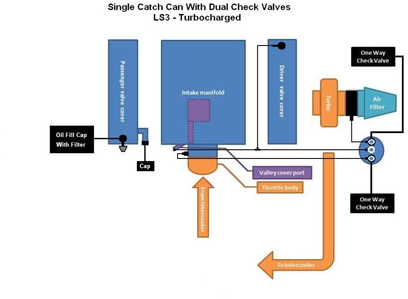
Now on to FI specific:
The 2 different FI models of RX oil separator
You have 2 styles of FI can. The top mount super chargers (Maggie, KB, Whipple, E-Force) directly pressurize the cylinder head runners so no intake manifold. This requires only 1 check valve as your only dealing with the crankcase evac and the excess pressure in the crankcase. The RX can will evac at all operation levels using the vacuum provided by the top mount head unit itself and will prevent any back-flow or reversion.
For the turbo or front mount super charger you have a completely different set of challenges to overcome and the RX dual valve unit is the ONLY oil separating can on the market to address this. The turbo/SC pressurizes the OEM or aftermarket intake manifold when building boost and besides the additional blow-by resulting in excess crankcase pressure, you also have any connection to the intake manifold allowing the boost to leak into the crankcase causing even more issues. When your at idle or non-boost cruising the intake manifold is not positive pressurized and acts as a NA application providing the vacuum needed to evac the crankcase. But when in boost, the intake manifold is pressurized and there is no vacuum source. The kit manufacturers of these (STS, ProCharger, Vortech, etc.) just send a check valve to close when under boost, but this prevents any effective crankcase evac and not only is there the pressure to deal with, but the harmful combustion byproducts are left in the crankcase where they cause damage over time.
The RX can uses the intake manifold vacuum for evac during non-boost operation, and when boost is detected it closes the valve to the intake manifold and the second valve opens using the inlet side of the head unit (turbo/SC) for a vacuum source so no matter what the level of operation the crankcase is evacuated and excess pressure is dealt with. When you let off the gas and fall back into non-boost operation the valves open & close in just the opposite ensuring no oil into the intake system AND proper crankcase evacuation at all times.
The problems with the solution the FI manufacturers include is it is only effective at part of your operating and results in excess crankcase pressure carrying oil vapor/mist into the intake air charge when in boost so you experience detonation and the rest of the issues related to oil ingestion.
Now, for a breathered can. The ONLY time you would use a breathered can is if you have a external vacuum pump that is evacuating the crankcase and this pressure is bled off into a liquid overflow containment container that needs a breather to allow the pressure to vent out.
There is NO time that this would be effective on a NON vacuum pump application. Those that do this are only relieving excess crankcase pressure and are NOT evacuating the harmful combustion byproducts so unless it is a race/track only build using a external vacuum pump and yes, we offer this solution.
To sum it up, anyone trying to use breather only or a breathered catch can on a non vacuum pump motor are never removing the unburnt fuel, carbon particles, sulfuric acid, and the other harmful byproducts that accumulate in the crankcase from running.
Understanding oil contamination from combustion byproducts
The evac system is not for the environment....it is to keep the engine alive and wear free as long as possible. Your not alone and 99% of car owners never think about it or realize whats happening over time. And yes, most will drive 50-75-100k plus miles and never know the damage gradually being done.
My qualifications?
over 35 years building race and performance engines.
Mechanical & Automotive engineer by trade
Graduate of the Reher Morrison Racing engine building school (one of the most respected in the world and a GM R&D contractor).
Owner and driver of drag teams with multiple Divisional, National & World championships in both NHRA & IHRA in several classes (this is where every minute detail in an engine matters)
And I tear down and build most every kind/brand of motor imaginable (except diesel) on a weekly basis.
So here goes:
Every motor has a certain amount of blow-by, the bigger the CI & the more boost the more blow-by (with everything else assumed is equal and no piston/ring/cylinder issue).
Most only look at the crankcase pressure portion and deal with that and that is only a small part of the crankcase evac systems function. The most important is the flushing & removal of the harmful combustion products before they have a chance to condense & settle into the crankcase oil.
These consist of:
Unburnt fuel
Carbon monoxide
water vapor
carbon particles
and several other harmful compounds that when mixed in the crankcase produce Sulfuric acid and as that accumulates past a certain PPM the bearing surfaces, wrist pins, and crank journals begin to be etched and start to damage. This is gradual of course so that�s why like you, most never realize whats happening.
The other very harmful byproduct is the very abrasive carbon particles (near diamond-like in abrasiveness) that many are to small to be caught by the oil filter and accelerate wear as well.
If you have a good cross flow of filtered fresh air entering one side of the crankcase (best is through a flow controlled breather), say the pass side oil fill cap, that fresh air will travel through the pass side valve cover, around the rockers, down the pushrod valley, through the center of the crankcase, (now on the LS6/2/3 valley cover with the fixed orifice it exits there drawn by vacuum so 1/2 the engine is still stagnant with foul compounds...especially the drivers side rocker area) up the drivers side pushrod valley, past the rockers and exits the rear of the drivers side valve cover flushing and pulling the compounds out BEFORE they can settle and condense into the crankcase. Now with out that flow the compounds settle and mix with the oil every time the engine cools. When started and run to operating temp the volatile of those are "flashed off" and again could be evacuated but if just venting with breathers, ONLY the excess crankcase pressure will exit and very little of the harmful compound mix goes with it and once the abrasive carbon particles mix with the oil they are there to stay reducing the protection your oil provides. Now if changing your oil after every track event then this is not an issue. But with a street driven car it is and I can tell you to just look at how dirt your oil gets as far as coloration when you eliminate the evacuation portion of a PCV system, but that tells very little. Send in an oil sample to a good analysis lab and the report back will verify everything I'm saying. The over the road trucking industry does this as a rule, and we do with our race engines as well looking for metal content that tells us a bearing is going away before we could ever detect it and knowing to freshen before a catastrophic failure.
Now back to the LS engine. Any built, big cube, or FI motor cannot breath using the valley cover fixed orifice as it is far to restrictive and excess pressure is a given. So we never use the valley cover vent tube but draw from the rear of the drivers side valve cover.
Now we come to the issue of FI builds that pressurize the intake manifold. Turbo or front mount centri SC systems, the problem with the OEM style system is as soon as you are under boost and the intake is under positive atmosphere you are pressurizing the crankcase directly via the vacuum nipple that evacs under non boost.
The only true solution for street driven cars is a oil separating crankcase evac system that will provide proper, continuous evac while operating under non-boost via the intake vacuum, and as soon as it senses pressurization a check valve senses this and closes blocking any chance of crankcase pressurization. Then as this happens a secondary valve opens and uses the suction/vacuum of the head unit to continue evacuation while the separating can traps & removes all the oil in suspension allowing only the gasses that do not effect the energy released per explosive event (you do NOT want ANY oil entering the intake air charge or residue/varnish forming on the compressor wheels throwing them off balance).
No oil caused detonation, no shortened engine life/increased wear, and the best of everything you need for the motor to perform properly & last as long as possible.
Now on to FI specific:
The 2 different FI models of RX oil separator
You have 2 styles of FI can. The top mount super chargers (Maggie, KB, Whipple, E-Force) directly pressurize the cylinder head runners so no intake manifold. This requires only 1 check valve as your only dealing with the crankcase evac and the excess pressure in the crankcase. The RX can will evac at all operation levels using the vacuum provided by the top mount head unit itself and will prevent any back-flow or reversion.
For the turbo or front mount super charger you have a completely different set of challenges to overcome and the RX dual valve unit is the ONLY oil separating can on the market to address this. The turbo/SC pressurizes the OEM or aftermarket intake manifold when building boost and besides the additional blow-by resulting in excess crankcase pressure, you also have any connection to the intake manifold allowing the boost to leak into the crankcase causing even more issues. When your at idle or non-boost cruising the intake manifold is not positive pressurized and acts as a NA application providing the vacuum needed to evac the crankcase. But when in boost, the intake manifold is pressurized and there is no vacuum source. The kit manufacturers of these (STS, ProCharger, Vortech, etc.) just send a check valve to close when under boost, but this prevents any effective crankcase evac and not only is there the pressure to deal with, but the harmful combustion byproducts are left in the crankcase where they cause damage over time.
The RX can uses the intake manifold vacuum for evac during non-boost operation, and when boost is detected it closes the valve to the intake manifold and the second valve opens using the inlet side of the head unit (turbo/SC) for a vacuum source so no matter what the level of operation the crankcase is evacuated and excess pressure is dealt with. When you let off the gas and fall back into non-boost operation the valves open & close in just the opposite ensuring no oil into the intake system AND proper crankcase evacuation at all times.
The problems with the solution the FI manufacturers include is it is only effective at part of your operating and results in excess crankcase pressure carrying oil vapor/mist into the intake air charge when in boost so you experience detonation and the rest of the issues related to oil ingestion.
Now, for a breathered can. The ONLY time you would use a breathered can is if you have a external vacuum pump that is evacuating the crankcase and this pressure is bled off into a liquid overflow containment container that needs a breather to allow the pressure to vent out.
There is NO time that this would be effective on a NON vacuum pump application. Those that do this are only relieving excess crankcase pressure and are NOT evacuating the harmful combustion byproducts so unless it is a race/track only build using a external vacuum pump and yes, we offer this solution.
To sum it up, anyone trying to use breather only or a breathered catch can on a non vacuum pump motor are never removing the unburnt fuel, carbon particles, sulfuric acid, and the other harmful byproducts that accumulate in the crankcase from running.