
Closed Loop Lean Cruise Idea (O2 Switch Points)
 Oct 25, 2007 | 01:59 PM
#1

Thread Starter
Resident Retard
iTrader: (31)
Joined: Jan 2006
Posts: 17,216
Likes: 20
From: Fort Worth - TX
I have an idea I would like to run by the tuning experts....
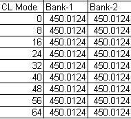
It is my understanding that Closed Loop AFR is partially controled by the O2 Switch Points table. Most truck tunes I have looked at have 450mv loaded in the O2 Switch Point table with the exception of some stock 6.0L trucks are richer, and this is why STFTs and LTFTs try to achieve ~14.63 AFR.
For example my stock tune:
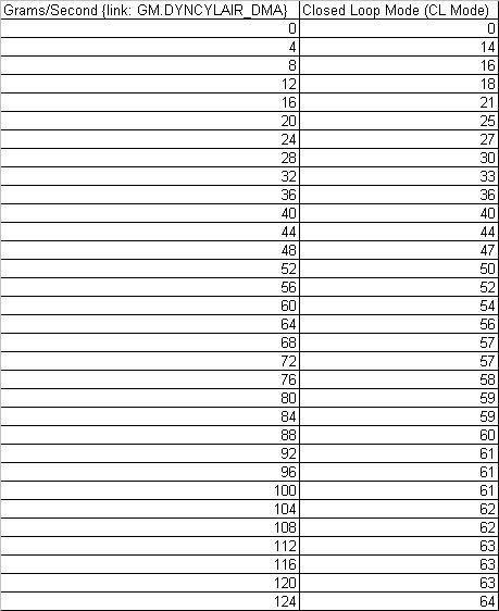
Now each Closed Loop Mode corresponds to a Grams/Second {link: GM.DYNCYLAIR_DMA} value via the Closed Loop Mode table.
For example my Stock Table (this in only half the values, sorry the table is too big)
Combining both tables together

So given a certain Grams/Second in closed loop the computer will try and achive the corresponding AFR via the Switch Point Table.
Is this correct?
Now for the second part, if I were to change the AFR (15.5ish) in the lower MAP areas in my Commanded Fuel When in Open Loop table, then AutoVE tune. During AutoVE tuning also log DYNCYLAIR vs WB AFR to determine what CL mode corresponds to what AFR. I would also have to log WB AFR vs O2 sensor voltage to determine how the WB AFR translates to MilliVolts. After the VE table is dialed in for the lower AFR ranges, then you would have to tune the MAF to correspond.
Does this sound like it would work? I have been meaning to try it but I have not had the time to do any logging.....
It is my understanding that Closed Loop AFR is partially controled by the O2 Switch Points table. Most truck tunes I have looked at have 450mv loaded in the O2 Switch Point table with the exception of some stock 6.0L trucks are richer, and this is why STFTs and LTFTs try to achieve ~14.63 AFR.
For example my stock tune:
Now each Closed Loop Mode corresponds to a Grams/Second {link: GM.DYNCYLAIR_DMA} value via the Closed Loop Mode table.
For example my Stock Table (this in only half the values, sorry the table is too big)
Combining both tables together
So given a certain Grams/Second in closed loop the computer will try and achive the corresponding AFR via the Switch Point Table.
Is this correct?
Now for the second part, if I were to change the AFR (15.5ish) in the lower MAP areas in my Commanded Fuel When in Open Loop table, then AutoVE tune. During AutoVE tuning also log DYNCYLAIR vs WB AFR to determine what CL mode corresponds to what AFR. I would also have to log WB AFR vs O2 sensor voltage to determine how the WB AFR translates to MilliVolts. After the VE table is dialed in for the lower AFR ranges, then you would have to tune the MAF to correspond.
Does this sound like it would work? I have been meaning to try it but I have not had the time to do any logging.....
Last edited by BlackGMC; Oct 25, 2007 at 02:17 PM.
Oct 25, 2007 | 02:43 PM
#2

You're on the right track here. The tune tool incorrectly states dyncylair_dma as one of the linking PIDs. GM.DYNAIR or CALC.CYLAIR will be a better representation of data for that table. DYNCYLAIR is air mass per cylinder (per cycle) while DYNAIR is grams of air per second, calculated by DYNCYLAIR, number of cylinders and rpm.
DYNAIR = DYNCYLAIR x # of cylinders x rpm x 0.5 / 60
You can log dynair at anypoint in time and make these adjustments to the O2 switch points, not just during AutoVE.
You're on the right track for the AFR vs millivolt logging
You'll want to create a couple of maps similar to your VE table with DYNAIR as the data value in one and one of your NB02 values as the average value. Filter out all values that are not commanded AFR = 15.5.
If you find that your dynair values vary dramatically for the lean cruise region you're looking for, you might want to adjust the CL mode values accordingly, since the switch point adjustment is much lower resolution than that table.
Oct 25, 2007 | 02:53 PM
#3
Thread Starter
Resident Retard
iTrader: (31)
Joined: Jan 2006
Posts: 17,216
Likes: 20
From: Fort Worth - TX
The tune tool incorrectly states dyncylair_dma as one of the linking PIDs. GM.DYNAIR or CALC.CYLAIR will be a better representation of data for that table. DYNCYLAIR is air mass per cylinder (per cycle) while DYNAIR is grams of air per second, calculated by DYNCYLAIR, number of cylinders and rpm.
DYNAIR = DYNCYLAIR x # of cylinders x rpm x 0.5 / 60
DYNAIR = DYNCYLAIR x # of cylinders x rpm x 0.5 / 60
I do have one question, since the values of the Switch point table are in multiples of 8, does that mean that any value from 4 to 12 equals CL mode 8? Does that make sense?
Oct 25, 2007 | 03:05 PM
#4
So if you have 400mv on CL mode 8 and 500mv on CL mode 16, then at CL mode 12, you'll be targeting 450mv. Make sense?


Thread
Thread Starter
Forum
Replies
Last Post
pewter00
GMT 800 & Older GM General Discussion
11
Oct 20, 2023 05:40 AM
Tydriver
GM Engine & Exhaust Performance
45
Oct 23, 2015 09:19 PM
2002_Z28_Six_Speed
GM Drivetrain & Suspension
17
Oct 4, 2015 01:34 PM
Cammed4ever
GM Engine & Exhaust Performance
5
Sep 30, 2015 03:38 PM

