
Electrical GURU Needed , LED Tipped Toggle
 Oct 21, 2014 | 12:22 AM
#1

Thread Starter


Joined: Mar 2004
Posts: 1,817
Likes: 58
From: 30 Miles North of Atlanta
Hi Folks,
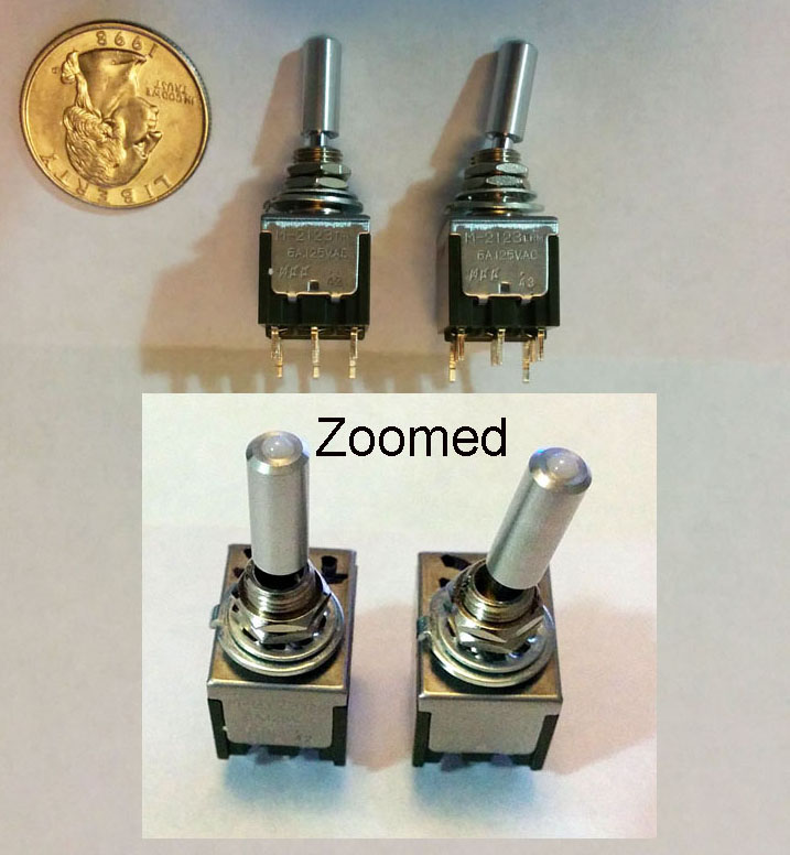
I have found some Bi-Color LED Tipped Toggle Switches I really like. They are small, Well Built, Short Throws, and have LED's on the tips that illuminate gently enough not to bother you at night and can be seen easily in daylight.
I seen these in a vehicle of an acquaintance I doubt I'll see again but asked about them and was told they are NKK Switches.
They are Double Pole, Double Throw and I want to use one for my dual battery setup:
Position 1 is Ign on = Isolator Contactor Connected (Green LED) Main & AUX Connected
Position 2 is Ign on or off = Isolator Contactor Not Connected (No LED) Main Only
Position 3 is Battery Power = Isolator Contactor Connected (Red LED) Main & AUX Connected, Key on or off. Feed will come from AUX
They are obviously not for heavy current but more like low AMP triggering current such as Relay triggers.
Long story short, not being an electrician I blew the LED circuit out of one. $12.00 down the drain.
There are two contact types, Gold and Silver being the one we need, and there is Isolated and Synchronous options but I believe I need Isolated.
I blew the LED out because they require external power with Ballast Resistors.
I need someone kind and willing to help me paint by the numbers here and hopefully themselves and the onlookers here will enjoy these switches if needed.
They are really clean looking little switches that have a small foot print
Poor me, I need it explained like the below, the numbers are hypothetical.
� Put the position 1 device line in on 3
� Put the position 1 device line out on 1
� Put the position 3 device line in on 6
� Put the position 3 device line out on 4
� Position 2 is an off position, nothing attached
LED Connections
� Attach one end of a xxΩ/xxW resistor(s)to ?
� Attach the other end(s) to ?
And so on
Here is a link to the NKK PDF - See Page A79
http://bit.ly/1pvTcEL
Thank You
Oct 23, 2014 | 12:55 PM
#2
I am fairly confused about what your trying to do......
Position 1 shouldnt need a toggle if you use your ignition switch to energize the contactor coil. If you do it that way all that is needed is a two position (on/off) single pull single throw toggle to energize the contactor coil when the ignition switch is off.
Am I missing something?
Position 1 shouldnt need a toggle if you use your ignition switch to energize the contactor coil. If you do it that way all that is needed is a two position (on/off) single pull single throw toggle to energize the contactor coil when the ignition switch is off.
Am I missing something?
Oct 24, 2014 | 02:22 AM
#3
Thread Starter
Joined: Mar 2004
Posts: 1,817
Likes: 58
From: 30 Miles North of Atlanta
Thanks,
In position one I am allowing the ignition circuit to enable the contactor.
In position two (off position) I am disabling the ignition circuit from enabling the contactor and the AUX battery is isolated at all times.
In position three the AUX battery power would be the line in for manually enabling the contactor if I see the need with the key off or want to jump start myself off if the main fails.
Oct 24, 2014 | 12:54 PM
#4
Ok, so let me get this straight......Unless the toggle is in position 1 the ignition switch wont energize the coil in the contactor? So you have a switch triggering a switch triggering the coil contactor? I suppose thats ok but its redundant. You really only need to use the toggle for position 2 and 3. And what exactly is your question about wiring the toggle? Is it the LED circuit your having issues with or the main circuit?
Oct 24, 2014 | 03:17 PM
#5
Thread Starter
Joined: Mar 2004
Posts: 1,817
Likes: 58
From: 30 Miles North of Atlanta
Thanks,
I want the position 2 to have the truck in a mode as if it only has one battery. More about how I have it terminated later. (I get home from work @11 EST)
Yes, I don't know how to properly configure the LED circuit. It's all on that pdf but I am not that electronical.
I want the position 2 to have the truck in a mode as if it only has one battery. More about how I have it terminated later. (I get home from work @11 EST)
Yes, I don't know how to properly configure the LED circuit. It's all on that pdf but I am not that electronical.
Oct 24, 2014 | 11:29 PM
#6
http://i199.photobucket.com/albums/a...ps4cac8669.jpg
Ok, so I got some time tonight to go through the PDF and came up with the above wiring diagram.
For the Red LED: 1.7v @ 10mA with a 12v power supply = 1.2k ohm, 1/4w resistor
For the Green LED: 2.0v @ 10mA with a 12v power supply = 1.0k ohm, 1/4w resistor
(These values were calculated on a basic online calculator)
If you look at the above diagram:
When the ignition switch is sent 12v from pin 2 to pin 1, pin 7 also recieves 12v which then goes through the green diode, through pin 9, then through the 1.0k ohm resistor to ground. (Ignition switch connected = green LED on)
When the battery contactor is sent 12v from pin 2 to pin 3, pin 7 is grounded through pin 6 which is connected to pin 5. The red diode recieves 12v which travels through the 1.2k ohm resistor to pin 9 then through pin 7, 6, and 5 to ground. (battery contactor on/ignition switch off = red LED on)
I put this all together pretty quickly and not sure how clear it all is to you. If you have any questions just ask. Hope this helps some!
Oct 25, 2014 | 12:39 AM
#7
Thread Starter
Joined: Mar 2004
Posts: 1,817
Likes: 58
From: 30 Miles North of Atlanta
Man! Thanks! Life Saver!
I'm not that electrical so I really appreciate the hand holding on this one.
I seen some 1KΩ-1/2 Watt and some 1.5kΩ-1/2Watt units today. You specified a 1.2kΩ on one side. Would the 1.5Ω work? If not I'll hit another vendor. Is the 1/2 Watt rating correct?
The switches are Really nice units. Classy compared to the generic and plastic stuff out there. The small footprint is nice too.
On my 2005 and several other year models there is an unused two wire connector dangling behind the AC drier on the fire wall that is used for the dual battery option or snow plow option. Its ignition on and already fused. Very convenient.
I purchased the female side and the ground side went to the ground side of the contactor and the positive is running through a Hella Time On Delay relay to close in 100 seconds.
I do this because I want to fire up on the main battery only so I know its fine and to let it recover a bit ahead of the AUX but mainly for a Main Battery Healthy confirmation. All this with position 1. Position 2 is a "My truck only has one battery" mode. And 3 is connected with ign or not.
Trending Topics
Oct 25, 2014 | 01:35 AM
#8
Thread Starter
Joined: Mar 2004
Posts: 1,817
Likes: 58
From: 30 Miles North of Atlanta
Oops, One more.
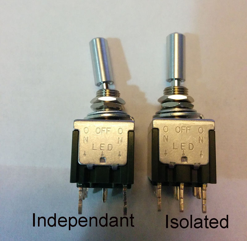
I just went to order the switch and there are two options of which I don't know the one you were looking at. The option is "Connected Power Terminals".
There is the 2122 on-none-on
There is the 2123 on-off-on
Thanks
I just went to order the switch and there are two options of which I don't know the one you were looking at. The option is "Connected Power Terminals".
There is the 2122 on-none-on
There is the 2123 on-off-on
Thanks
Oct 25, 2014 | 04:48 PM
#9
Man! Thanks! Life Saver!
I'm not that electrical so I really appreciate the hand holding on this one.
I seen some 1KΩ-1/2 Watt and some 1.5kΩ-1/2Watt units today. You specified a 1.2kΩ on one side. Would the 1.5Ω work? If not I'll hit another vendor. Is the 1/2 Watt rating correct?
I'm not that electrical so I really appreciate the hand holding on this one.
I seen some 1KΩ-1/2 Watt and some 1.5kΩ-1/2Watt units today. You specified a 1.2kΩ on one side. Would the 1.5Ω work? If not I'll hit another vendor. Is the 1/2 Watt rating correct?
One other thing I should make you aware of is that following the above wiring diagram means you will have a current drain on your battery at all times if the 12v you feed the switch is constant. This is because, as you can see above the 12v goes through the 1.2k ohm and 1.0k ohm resistors to ground at all times. There is nothing breaking this circuit. However, using V=IR again, the current draw through this circuit given the 2.2k ohms of resistance would only be about 5.5mA. For reference, a car radio will draw somewere around 8mA when off for memorizing the radio station presets and clock. So this shouldnt cause any battery draining issues but just wanted you to be aware.
Last edited by 53bowtie; Oct 25, 2014 at 05:10 PM.

Thread
Thread Starter
Forum
Replies
Last Post