When you click on links to various merchants on this site and make a purchase, this can result in this site earning a commission. Affiliate programs and affiliations include, but are not limited to, the eBay Partner Network.
2014 Silverado, 5.3L, Truck runs and quit's etc. Codes coming back are P0232 & P023F.
What should I change first? Fuel Pump or Fuel Pump Control Module?
It's really hard to say because it's a pure guess without looking at the truck. Here is some diagnostic info to help you trace it. PLEASE UPDATE THIS THREAD AND LET US KNOW WHAT YOU FOUND AND WHAT FIXES IT. People rarely report back and nobody knows what to do when they search for these problems and there's no updates.
P0232
The fuel pump driver control module detects that the fuel pump output circuit voltage is greater than 4.0 V for 1 s when the voltage should be 0 V.
P023F
The fuel pump driver control module detects that the fuel pump current is less than 1 A and the fuel pump duty cycle is approximately 30-60 % for 1 s.
Circuit/System Testing
1. Ignition OFF and all vehicle systems OFF, disconnect the harness connector at the G12 Fuel Pump. It may take up to 2 min for all vehicle systems to power down.
2. Test for less than 5 ohms between the low reference circuit terminal 2 and ground.
♦ If 5 ohms or greater
1. Ignition OFF, disconnect the harness connector at the K111 Fuel Pump Driver Control Module.
2. Test for less than 2 ohms in the low reference circuit end to end.
♦ If 2 ohms or greater, repair the open/high resistance in the circuit.
♦ If less than 2 ohms, replace the K111 Fuel Pump Driver Control Module.
♦ If less than 5 ohms
3. Ignition ON, connect a test lamp between the supply voltage circuit terminal 1 and the low reference circuit terminal 2.
4. Verify the test lamp turns ON and OFF when commanding the Fuel Pump Enable On and Off with a scan tool.
♦ If the test lamp is always OFF
1. Ignition OFF, disconnect the harness connector at the K111 Fuel Pump Driver Control Module.
2. Test for infinite resistance between the supply voltage circuit and ground.
♦ If less than infinite resistance, repair the short to ground on the circuit.
♦ If infinite resistance
3. Test for less than 2 ohms in the supply voltage circuit end to end.
♦ If 2 ohms or greater, repair the open/high resistance in the circuit.
♦ If less than 2 ohms, replace the K111 Fuel Pump Driver Control Module.
♦ If the test lamp is always ON
1. Ignition OFF, remove the test lamp, disconnect the harness connector at the K111 Fuel Pump Driver Control Module, ignition ON.
2. Test for less than 1 V between the supply voltage circuit and ground.
♦ If 1 V or greater, repair the short to voltage on the circuit.
♦ If less than 1 V, replace the K111 Fuel Pump Driver Control Module.
But taking a shot in the dark, I'd probably go for the driver first since fuel pumps usually work or don't work.
However, the first thing I would do is check the connectors at each and see if one is funky, has water in it or has any issues at all. I would plug them back in and unplug a few times. Sometimes connections get a little funny and unplugging and replugging a few times will wipe the pins and give a better connection. Don't count on this though it's rare it helps but it's worth a shot.
If you could do the testing above then you'll have your answer. Looks like you just need a test light. My favorite low cost easy to find test light is at Lowes, cobalt brand. I have a bunch of test lights lol.
Would you happen to have the pinout identification for the FPCM? GMFlash.com has a video for testing these but I didn't realize it was for a 2010, the 2014 is different from what they told me but I did not get a response from them on the pinout for the 2014. I already have it out of the truck so I figured if I could do a quick continuity check on it I might find the problem.
Would you happen to have the pinout identification for the FPCM? GMFlash.com has a video for testing these but I didn't realize it was for a 2010, the 2014 is different from what they told me but I did not get a response from them on the pinout for the 2014. I already have it out of the truck so I figured if I could do a quick continuity check on it I might find the problem.
Thanks
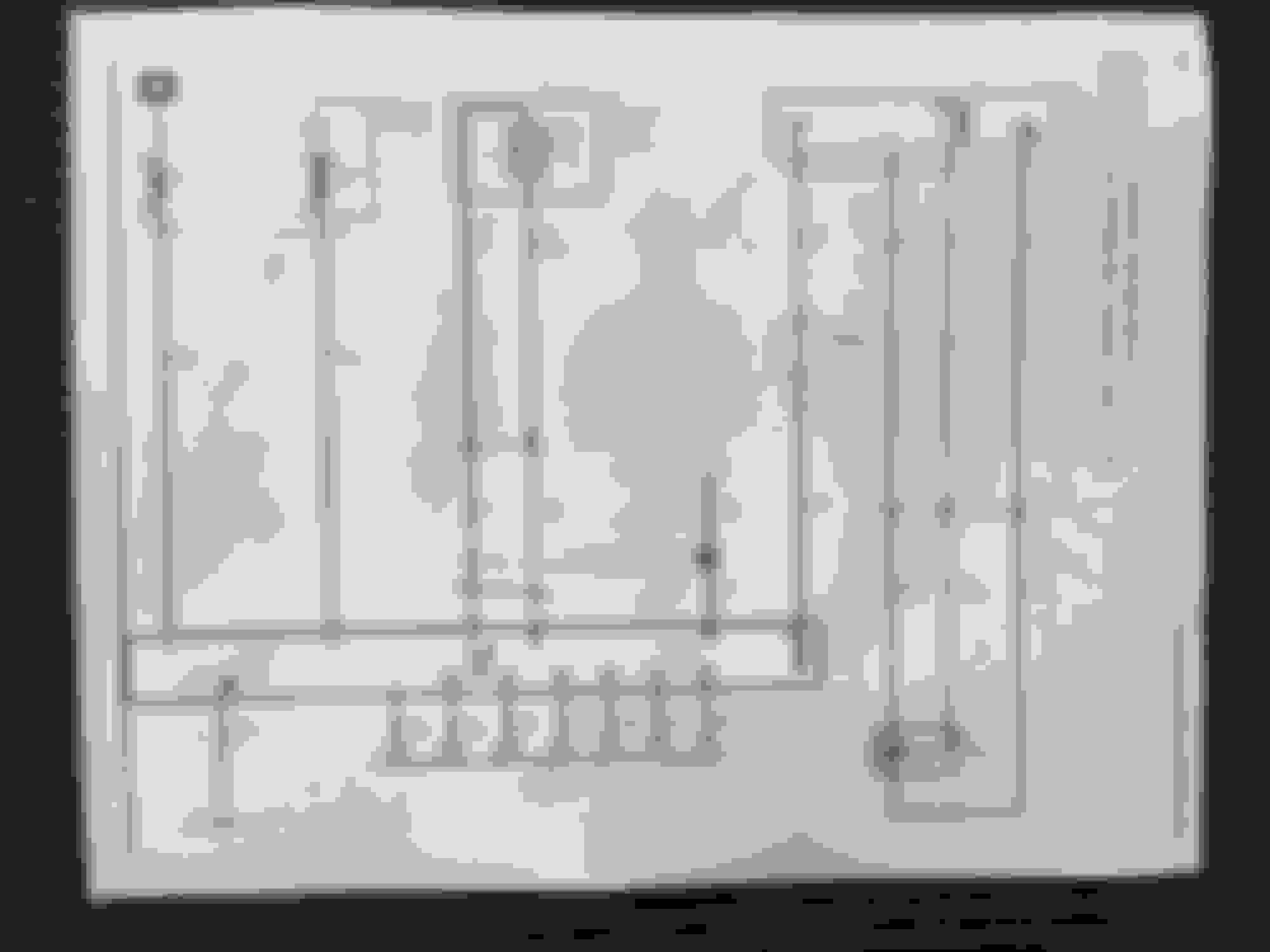
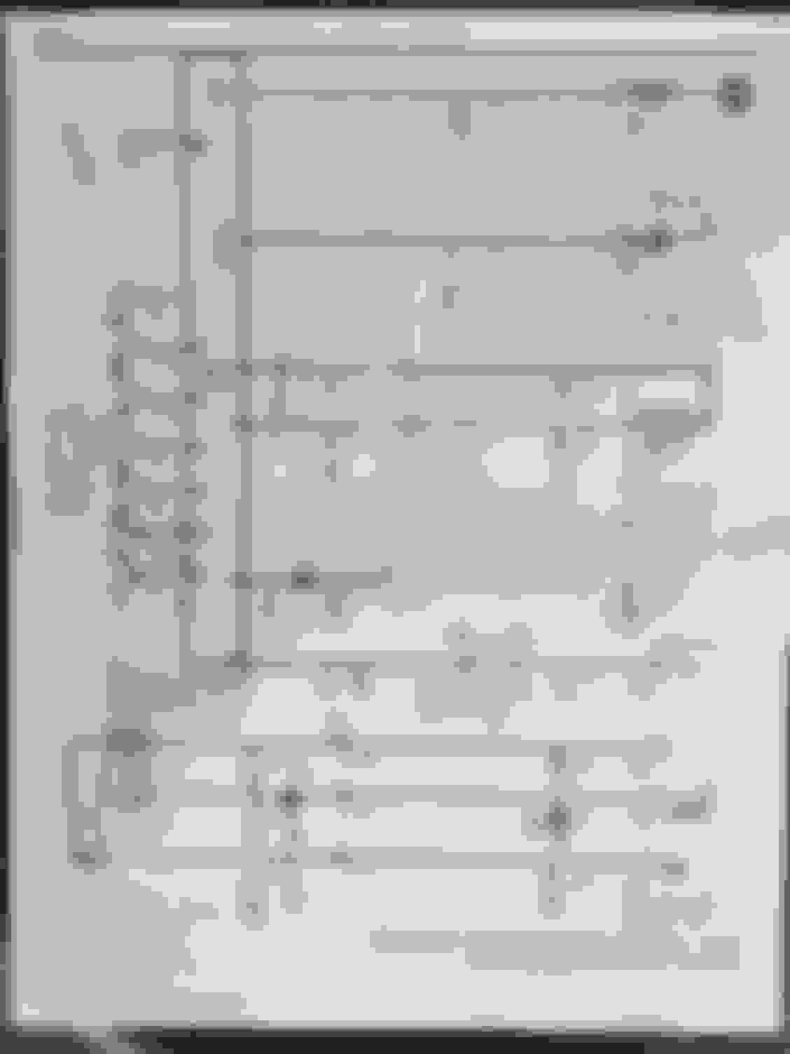
This POS alldata won't let me download the wiring diagrams. I'll try again later and see if I can find a way to post them.
The diagrams are horrible. Even on the computer you can't read them. I also couldn't copy the diagram in any way shape or form. Couldn't screen shot, couldn't copy paste, couldn't print screen. Apparently they locked out the ability to share the diagrams somehow.
So I printed it and had to write in the **** it said on it. This is the best I can get for ya.
OK, not sure how to correlate the K2XX schematic that you gave me to the pinout from GMFlash.com for the GMT900 truck module. According to GMFlash.com you just need to check pin 1(Ground), Pin 13 (FP Relay Control- Primary), Pin 15(Ign 1 Voltage) & Pin 32(Battery Positive Voltage to verify the FPCM is good, I would assume this would be the same for the K2XX connector but the pin numbers and wire colors are probably different.PIN1-3 BLK GROUND
PIN2-4 - NA
PIN5- GY LOW REF
PIN6- TN HIGH SPEED LAN-
PIN7- TN/BK HIGH SPEED LAN+
PIN8-9 - NA
PIN10- PU FUEL LINE PRESSURE SIGNAL
PIN11-12 - NA
PIN13- D-GN/WH FP RELAY CONTROL -PRIMARY
PIN14- - NA
PIN15- PK IGN 1 VOLTAGE
PIN16- PK LOW REF
PIN17- L-BU SERIAL DATA ENABLE 12+
PIN18-20 - NA
PIN21- TN HIGH SPEED LAN-
PIN22- TN/BK HIGH SPEED LAN+
PIN23-31 - NA
PIN32- RD/WH BATTERY POSITIVE VOLTAGE
PIN33-35 - NA
PIN36- BN 5-VOLT REF
PIN37-43 - NA
PIN44- GY FSCM SHIELD EXT
PIN45-46 - NA
PIN47- GY FUEL PUMP SUPPLY VOLTAGE
Sounds to me that basically if your truck runs and you have these codes then you should replace the driver.
If the truck runs then the fuel pump obviously works.
These codes are saying you either have an issue with the fuel pump, the pump driver, or wiring.
If the truck runs the pump works, rule that out.
If you don't think you have wiring problems slap a driver on it and see what it does.
Or run the tests it says to run in the diagnostic/repair chart I posted to confirm there is no wiring issues or anything causing the module to do something it's not supposed to (like having signal inputs it shouldn't)
I can't help you with crossing pinouts from various sources. The info I use in the shop all day every day is posted here. Mixing it with other info and sources is gonna cause confusion.
 04-27-2018, 12:15 PM