
l92 top end swap write up
 Oct 19, 2009 | 08:01 PM
#32

Thread Starter
On The Tree
Joined: Mar 2006
Posts: 182
Likes: 0
From: Chicago
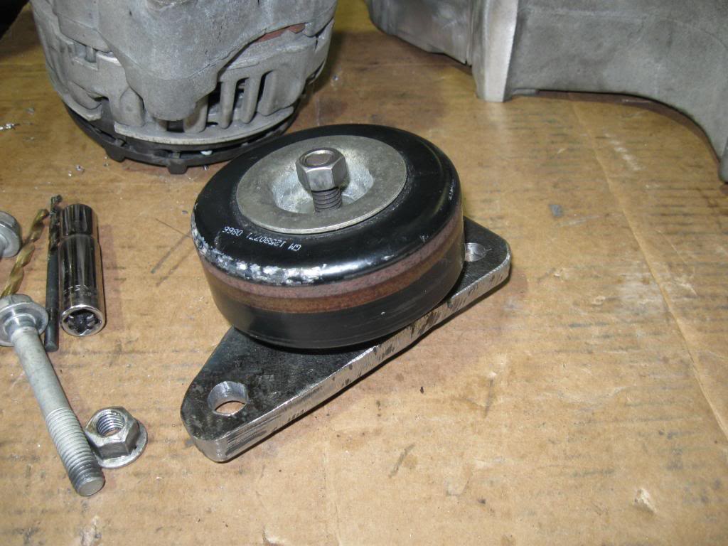
now with the idler out of the way you can start on the water pump problem. There is a few ways to do this as well i have an f-body pump so i choose that route, but if you have a 04 or earlier truck pump you will have both outlet bosses on the pump, so you can plug the top(truck) outlet and drill out the front(car) outlet. But i choose to use an f-body pump and swap pulleys. now after murdering the f-body pulley to get it off. then pulling the truck pulley, wich came off relatively easy and pressing it on the f-body pump i had the water pump situation under control
f-body pulley after removal
f-body pump minus pully
turck pump
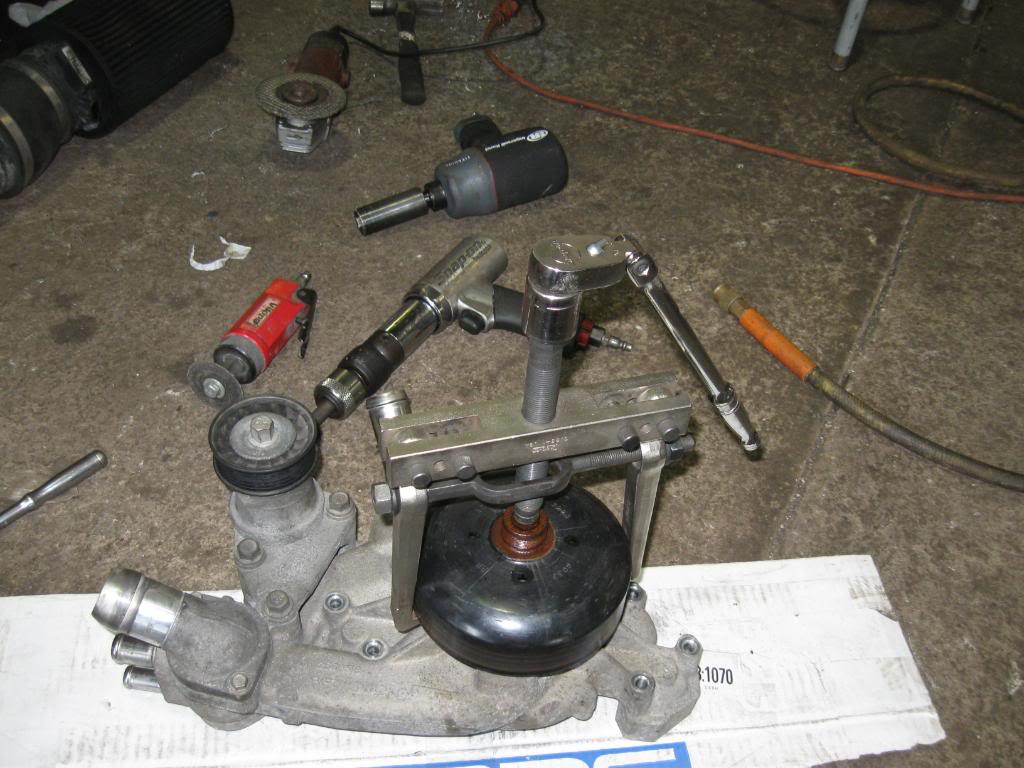
and what it all looks like together idler moved and pump outlet changed

f-body pulley after removal
f-body pump minus pully
turck pump
and what it all looks like together idler moved and pump outlet changed
Oct 19, 2009 | 08:03 PM
#33
Thread Starter
On The Tree
Joined: Mar 2006
Posts: 182
Likes: 0
From: Chicago
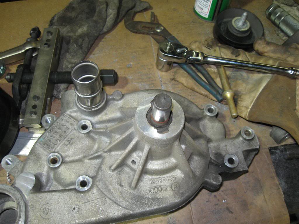
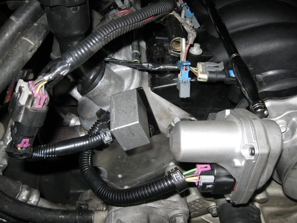
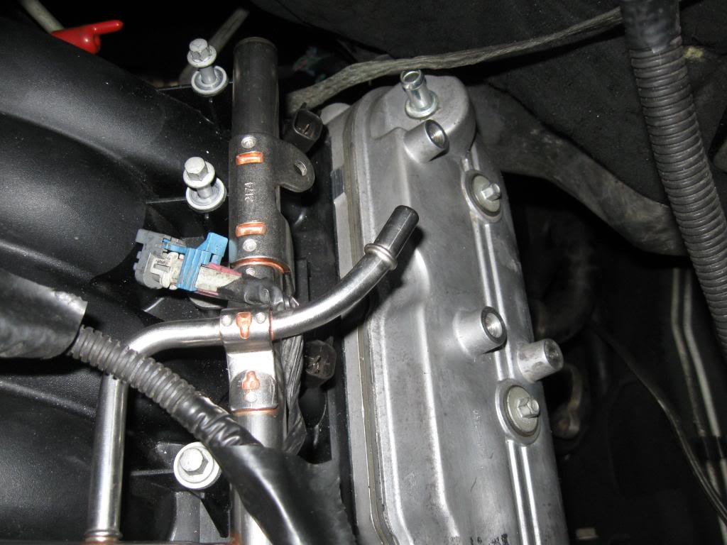
and heres a pic of the pump to throttle body clearance
one thing i did forget to mention is the coolant crossover tube has to be bent down a little cause it hits the bottom of the throttle body
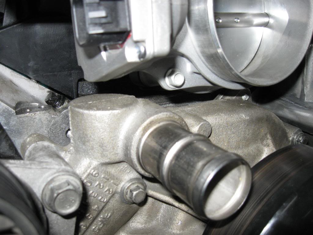
one thing i did forget to mention is the coolant crossover tube has to be bent down a little cause it hits the bottom of the throttle body
Last edited by 06WT; Oct 21, 2009 at 09:21 PM.


 Oct 20, 2009 | 06:43 PM
#36
Thread Starter
On The Tree
Joined: Mar 2006
Posts: 182
Likes: 0
From: Chicago
Oct 21, 2009 | 05:48 PM
#37
Thread Starter
On The Tree
Joined: Mar 2006
Posts: 182
Likes: 0
From: Chicago
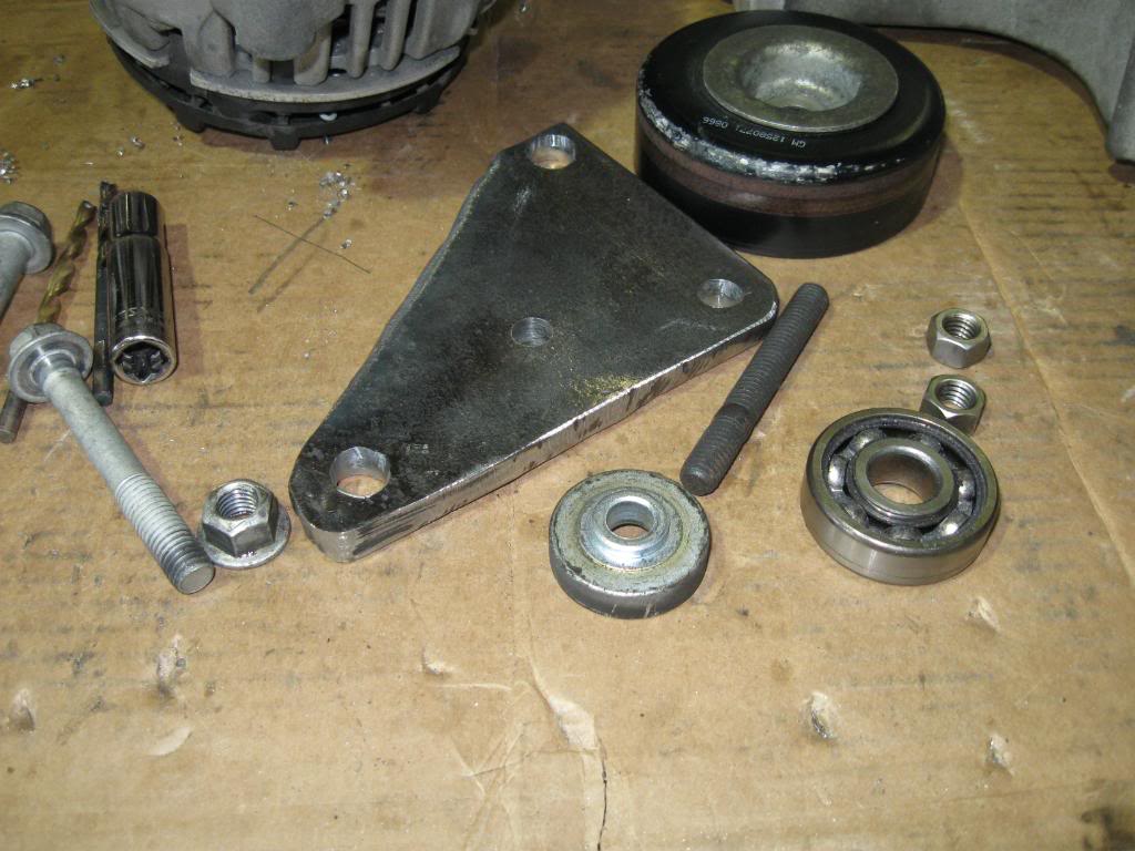
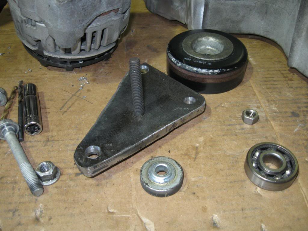
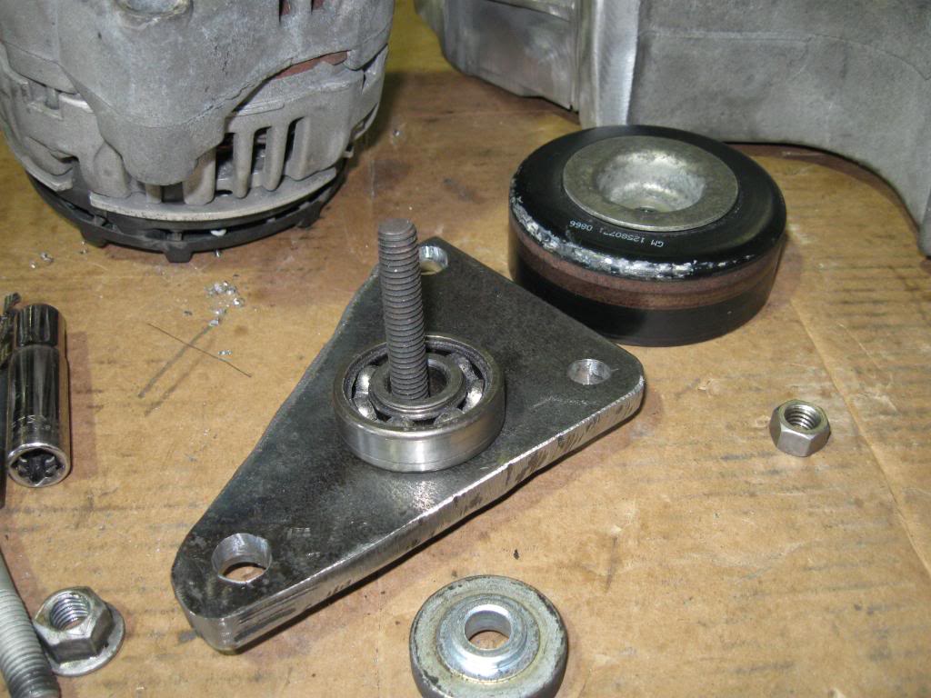
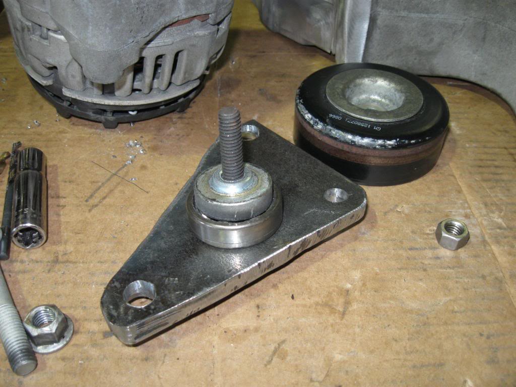
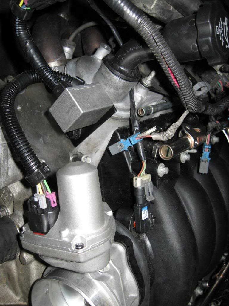
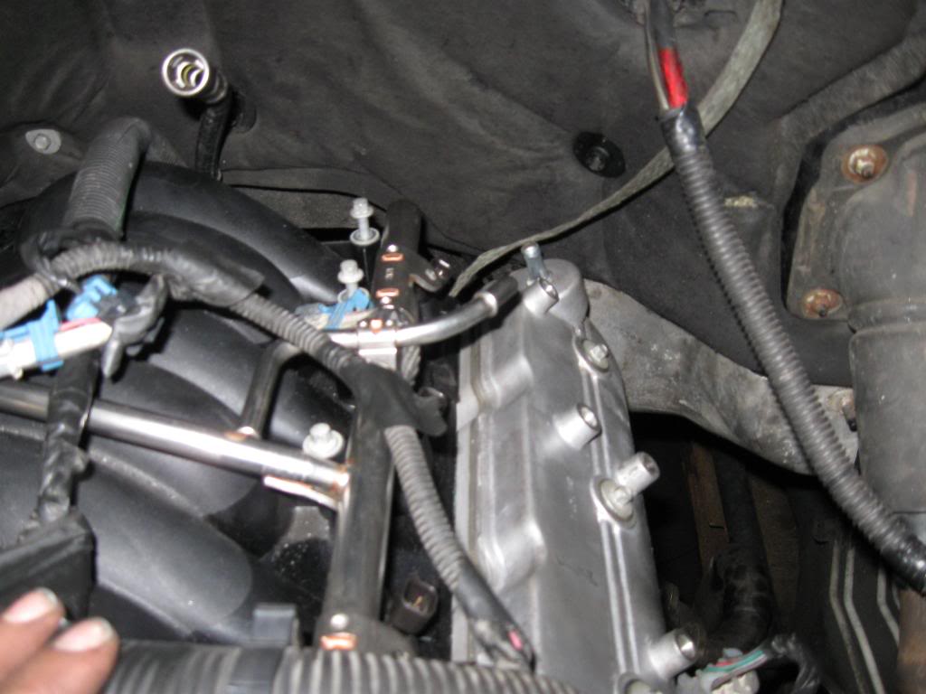
alright heres the TRP X-Link 2.1 mounted to a bracket i made and the map sensor extended and ran through the injector loom to the front of the motor
And for the trp x-link it comes in the instructions but they are kind of unclear, if you have car manifoild cut the pink loops and insulate them. I just put some heat srink tubing over the ends of the pink loops after i cut them. if you have the truck intake leave the pink loops alone. The pink loops im talking about are on both ends of the harness in the black protective loom
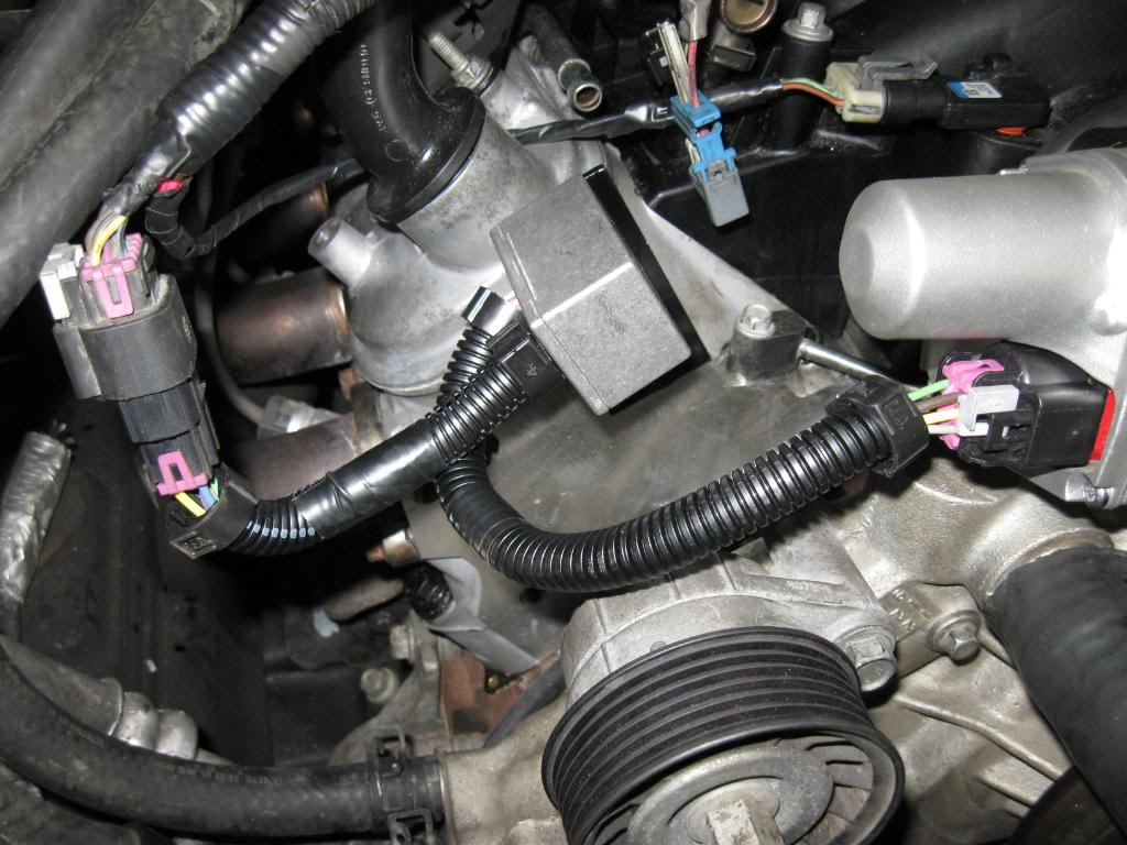
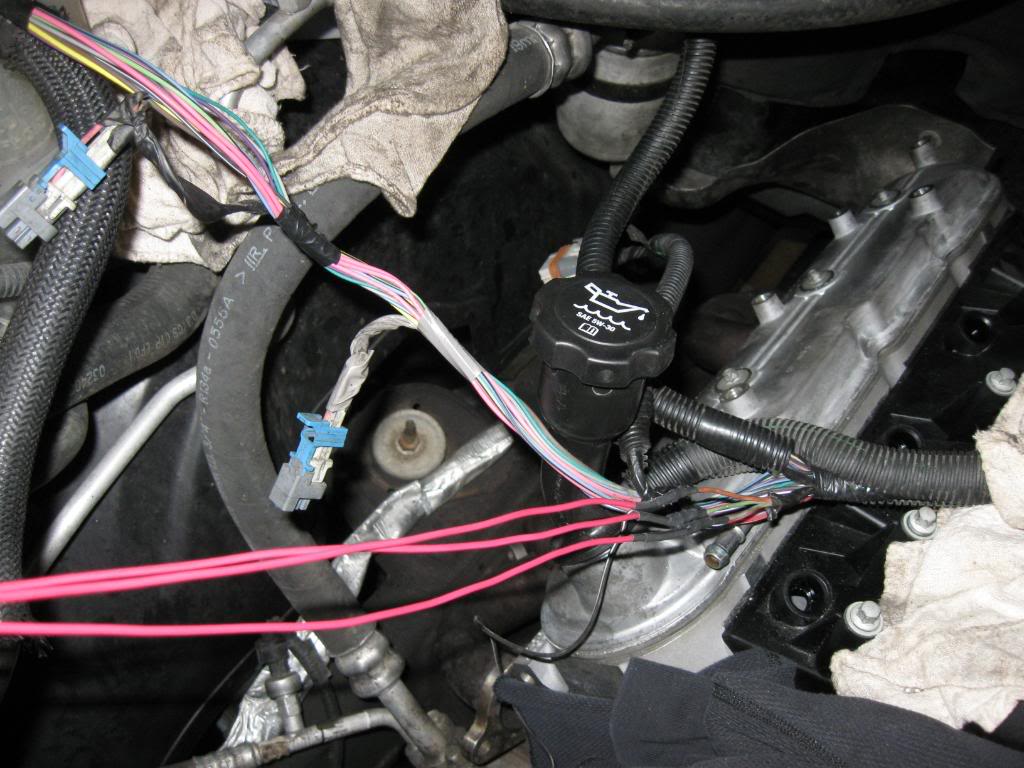
And for the trp x-link it comes in the instructions but they are kind of unclear, if you have car manifoild cut the pink loops and insulate them. I just put some heat srink tubing over the ends of the pink loops after i cut them. if you have the truck intake leave the pink loops alone. The pink loops im talking about are on both ends of the harness in the black protective loom
Last edited by 06WT; Oct 21, 2009 at 06:12 PM.
Oct 21, 2009 | 05:55 PM
#38
Thread Starter
On The Tree
Joined: Mar 2006
Posts: 182
Likes: 0
From: Chicago
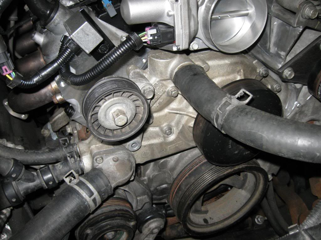
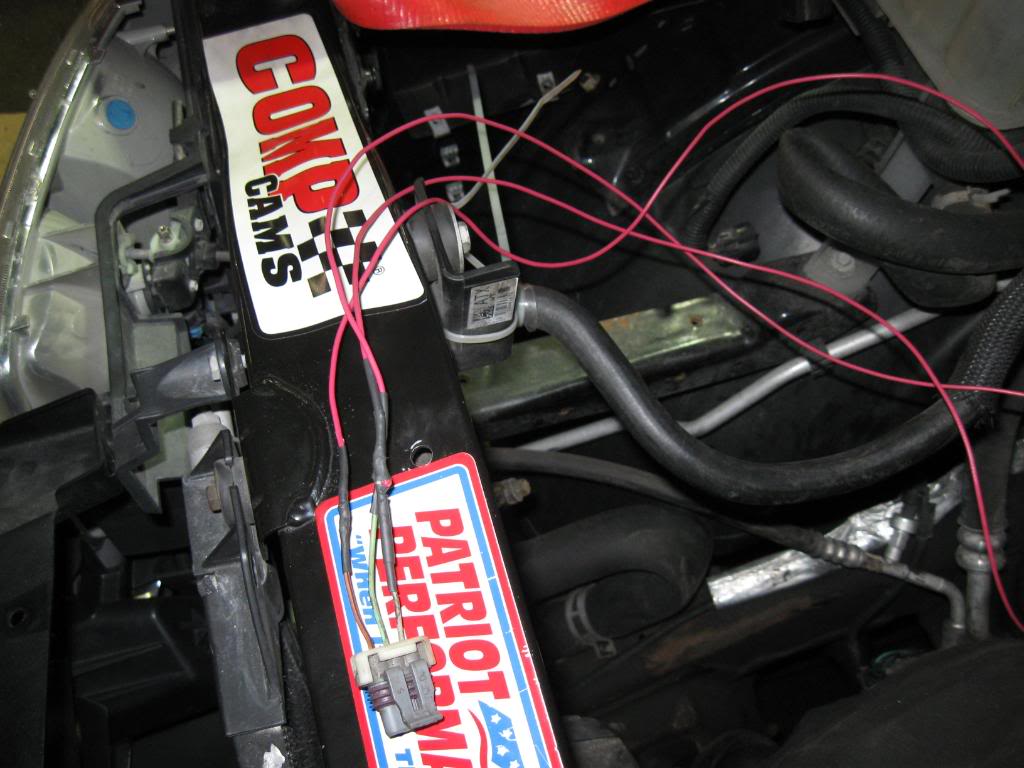
and as for the fuel rail crossover tube inlet, i just bent it back a little cause i did not want to cut the inlet and make a new fitting for the inlet to be parallel to the motor, cause i didnt want to put extra stress on the solder joint on the crossover tube.
 Oct 21, 2009 | 06:35 PM
#40
Thread Starter
On The Tree
Joined: Mar 2006
Posts: 182
Likes: 0
From: Chicago
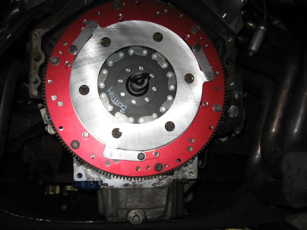
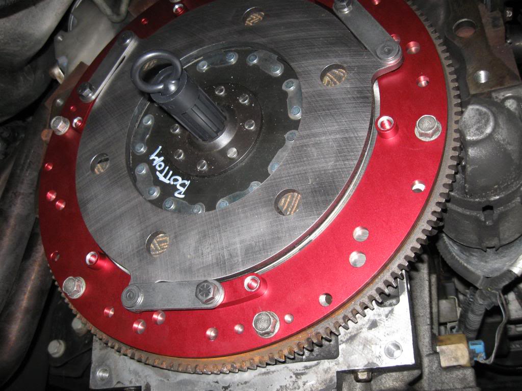
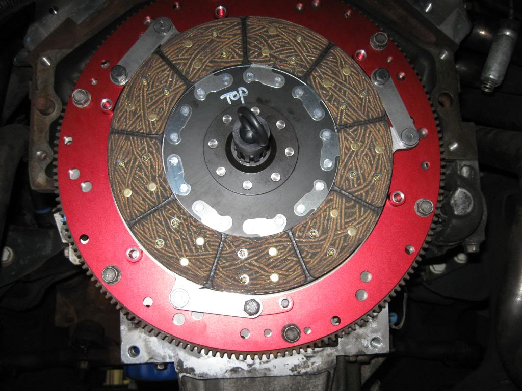
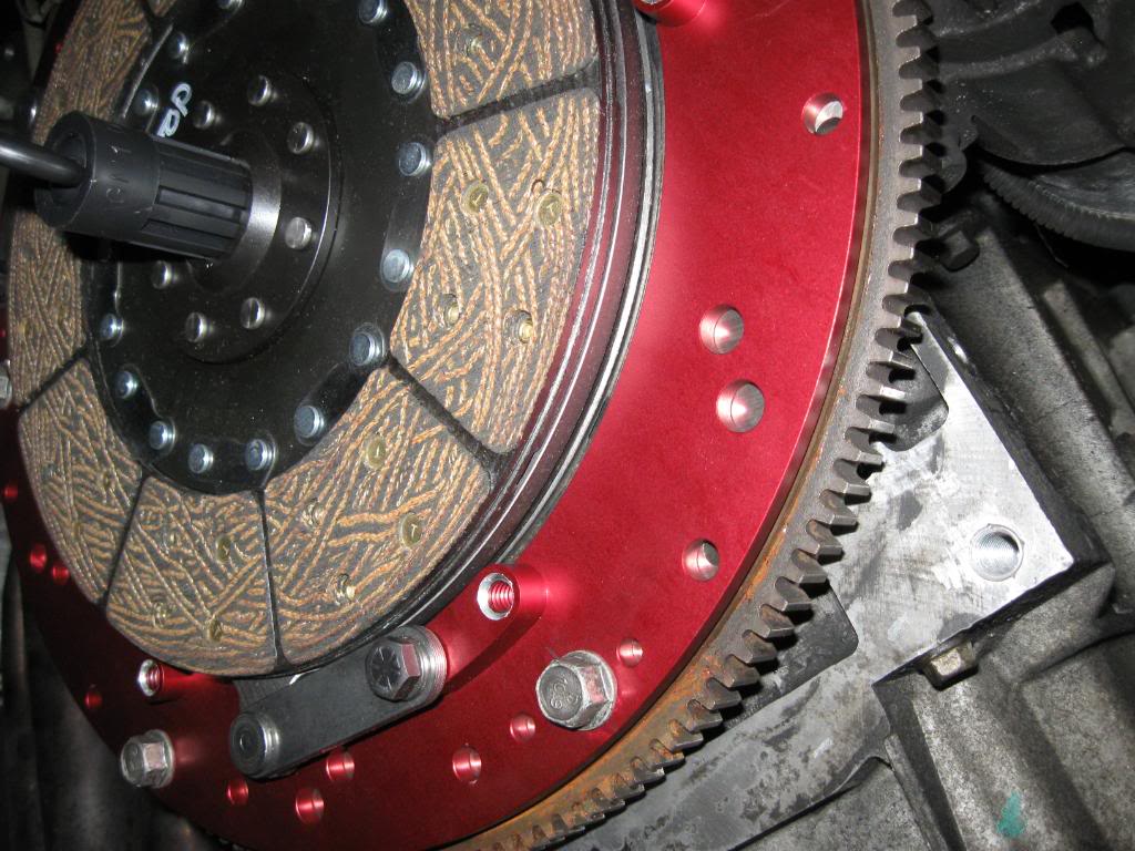
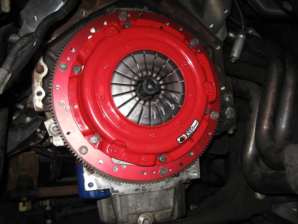
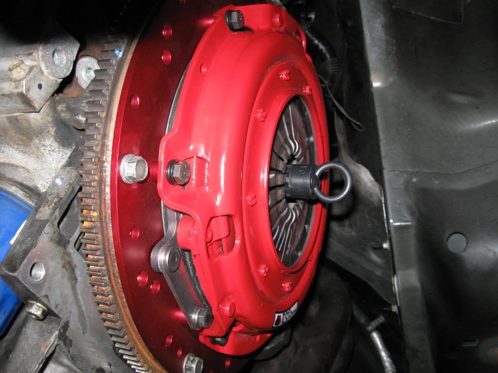
now on to the twin disc, i know almost all of you guys are auto, but for the small fraction of us who like 3 pedals heres my pics and install of a mcleod twin disc clutch.
well if you dont have a new billet flywheel from mcleod you will have to get a stock ls1 flywheel, because the inside diameter of the truck flywheel is too large. so once you have a new or newly machined ls1 flywheel you can bolt it up to torque spec and install a new pilot bearing.
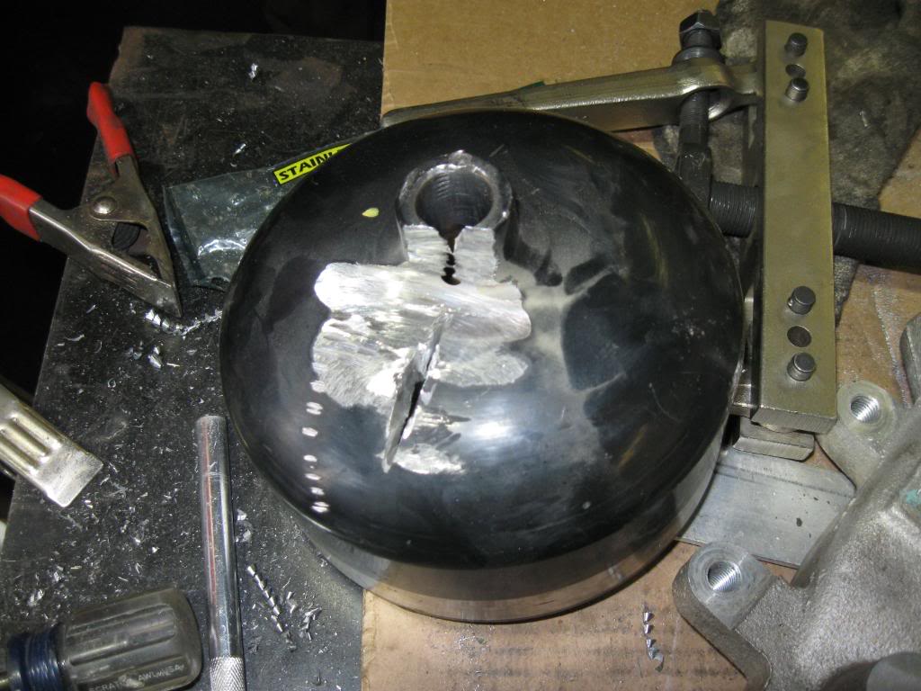
now in the mcleod box there is the clutch assembly and the second disc, first thing to do is unbolt the pressure plate from the floater ring. then grab the second disc labled bottom, and the floater ring and place the bottom disc inside the floater assembly with the flywheel lable twords the flywheel and bolt the ring up with the stock pressure plate bolts. leave the the ring bolts sung so the flywheel side disc can still move around. then grab the first disc and the alignment tool , and align the discs with the pilot. and with the alignment tool still in place bolt the pressure plate on and torque it down in a star pattern
well if you dont have a new billet flywheel from mcleod you will have to get a stock ls1 flywheel, because the inside diameter of the truck flywheel is too large. so once you have a new or newly machined ls1 flywheel you can bolt it up to torque spec and install a new pilot bearing.
now in the mcleod box there is the clutch assembly and the second disc, first thing to do is unbolt the pressure plate from the floater ring. then grab the second disc labled bottom, and the floater ring and place the bottom disc inside the floater assembly with the flywheel lable twords the flywheel and bolt the ring up with the stock pressure plate bolts. leave the the ring bolts sung so the flywheel side disc can still move around. then grab the first disc and the alignment tool , and align the discs with the pilot. and with the alignment tool still in place bolt the pressure plate on and torque it down in a star pattern