Shimmy: Measured pinion angle - need some help now
 09-07-2006, 12:13 PM
#11
TECH Fanatic
Thread Starter
iTrader: (4)

Join Date: Jun 2003
Location: Chicago Burbs
Posts: 1,528
Likes: 0
Received 0 Likes
on
0 Posts
You beat me to it, I just posted in the other thread that I assumed the angle of the pinion didn't change when doing the shackle, but what you are showing makes sense, I would need fat end backward.
My problem still is that my pinion still points at a greater angle upward than my DS, so I still have a + pinion when all the reading I've done says it should be 0 or negative. Maybe my setup was somehow wrong from the beginning. I agree with you though, that, in theory I should just be putting the fat end backwards. I'm just gonna put the stockers back on this weekend, measure and make sure the shimmy is gone. Then put the drops back on and get the same angles. I'll post back on Monday. Thanks for straightening me out though.
My problem still is that my pinion still points at a greater angle upward than my DS, so I still have a + pinion when all the reading I've done says it should be 0 or negative. Maybe my setup was somehow wrong from the beginning. I agree with you though, that, in theory I should just be putting the fat end backwards. I'm just gonna put the stockers back on this weekend, measure and make sure the shimmy is gone. Then put the drops back on and get the same angles. I'll post back on Monday. Thanks for straightening me out though.
Last edited by agreif; 09-07-2006 at 12:20 PM.
 09-08-2006, 02:41 AM
#13
11 Second Club
iTrader: (1)

Join Date: Feb 2003
Location: Allen,Texas
Posts: 499
Likes: 0
Received 0 Likes
on
0 Posts
Originally Posted by agreif
measured the pinion angle both on the flatt on that diff housing, and on the actual pinion "yolk" that attached to the driveshaft, both read 5-6. didn't measure the trans though. Looks like that needs to be measured too. Guess I just assumed that was 0.
09-08-2006, 05:42 AM
#14
12 Second Truck Club
iTrader: (3)

Join Date: Feb 2006
Location: Baton Rouge
Posts: 1,457
Likes: 0
Received 0 Likes
on
0 Posts
U-joints cause vibration when the angles front and rear (tranny and pinion) are different because at a given angle the u- joint causes a vibration. The opposing u-joint which is at the opposite end of the shaft and is in phase basically cancels out the vibration with an opposing vibration. If they don't match closely, they will not cancel each other out and you will feel the vibration. That's the way I understand it.
Colby, I do dispute your theory to a point. Not saying it is totally wrong, but your picture does not take the rest of the driveline into account and only focuses on getting the pinion back to the stock angle. Yes the pinion is rotated down, but in most cases, it needs to be. I can promise you that there are trucks that have shackles only installed and still have a high pinion angle, which is opposite of what you depict in your picture. Also, to make your image more accurate, you should have not lowered the front hanger and you should have included the tranny in the pic. If the hanger was stationary, then the rotation of the axle would be more accurate and if the tranny was included in the picture, then the relationship of rear pinion to tranny tailshaft could be compared. But, if not to scale, it's pointless anyway.
IMO there are 2 rules to driveshaft allignment.
(1) If you have a standard 2 u-joint shaft, the tailshaft and pinion angles should be within a degree or two of each other (pinion down for axle wrap)
(2) If running a cv shaft, the pinion should point at the tailshaft (of couse down a degree or two for axle wrap)
09-08-2006, 07:39 AM
#15
12 Second Truck Club
iTrader: (3)
Join Date: Feb 2006
Location: Baton Rouge
Posts: 1,457
Likes: 0
Received 0 Likes
on
0 Posts
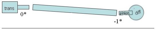
The way I understand it, If your Tranny Tailshaft Output were 0* then You would want your Pinion to be around -1* with a standard 2 u-joint, single shaft setup. Like so.
09-08-2006, 07:49 AM
#16
TECH Junkie

Join Date: Jul 2005
Location: Lake Conroe Texas
Posts: 3,205
Likes: 0
Received 0 Likes
on
0 Posts
Originally Posted by BigCountryx
Colby, I do dispute your theory to a point. Not saying it is totally wrong, but your picture does not take the rest of the driveline into account and only focuses on getting the pinion back to the stock angle. Yes the pinion is rotated down, but in most cases, it needs to be. I can promise you that there are trucks that have shackles only installed and still have a high pinion angle, which is opposite of what you depict in your picture. Also, to make your image more accurate, you should have not lowered the front hanger and you should have included the tranny in the pic. If the hanger was stationary, then the rotation of the axle would be more accurate and if the tranny was included in the picture, then the relationship of rear pinion to tranny tailshaft could be compared. But, if not to scale, it's pointless anyway.

The point was to show, in theory, what effect the shackles have on the differential - I could give a flying **** less if it's to scale or has accurate real world angles

goodday
 09-08-2006, 09:13 AM
#17
12 Second Truck Club
iTrader: (3)
Join Date: Feb 2006
Location: Baton Rouge
Posts: 1,457
Likes: 0
Received 0 Likes
on
0 Posts
Originally Posted by Colby 04
oh I'm sorry it's not to scale and doesn't depict an accurate pinion angle
The point was to show, in theory, what effect the shackles have on the differential - I could give a flying **** less if it's to scale or has accurate real world angles
goodday
The point was to show, in theory, what effect the shackles have on the differential - I could give a flying **** less if it's to scale or has accurate real world angles
goodday
And more than being to scale, both angles need to be taken into account not just the pinion angle. that's my point regardless if you give a flying **** or not.
09-08-2006, 10:17 AM
#18
TECH Junkie
iTrader: (2)
Join Date: Mar 2005
Location: Spring, TX
Posts: 3,197
Likes: 0
Received 0 Likes
on
0 Posts
I WANT TO SEE SOME MEASUREMENTS OF A 2-PIECE DRIVESHAFT!!!!
DO ALL OF YOU GUYS HAVE A ONE PIECE???
There are quite a few more variables with a 2 piece shaft!
Jim
DO ALL OF YOU GUYS HAVE A ONE PIECE???
There are quite a few more variables with a 2 piece shaft!
Jim
09-08-2006, 10:23 AM
#19
TECH Junkie
iTrader: (2)
Join Date: Mar 2005
Location: Spring, TX
Posts: 3,197
Likes: 0
Received 0 Likes
on
0 Posts
For example: If you have to use a carrier bearing relocator bracket the trans and carrier bearing will not be lined up anymore. Correct?
Then a tranny shim would be needed.
The final tailshaft of course would be lined up like you guys are stating, the carrier bearing acting as the tranny snout.
I will be definetely doing this the right way, and not half *** like most seem to be doing.
Jim
Then a tranny shim would be needed.
The final tailshaft of course would be lined up like you guys are stating, the carrier bearing acting as the tranny snout.
I will be definetely doing this the right way, and not half *** like most seem to be doing.
Jim
09-08-2006, 03:52 PM
#20
TECH Junkie
Join Date: Jul 2005
Location: Lake Conroe Texas
Posts: 3,205
Likes: 0
Received 0 Likes
on
0 Posts
Originally Posted by BigCountryx
Get as mad as you want, but you are not 100% correct. Your theory is that the fat end of the shim always goes to the back and you pinion always needs to be angled upward because shackles point you pinion down. You are wrong because depending on the vehicle, you may need to angle your pinion even farther downward, or maybe none at all.
And more than being to scale, both angles need to be taken into account not just the pinion angle. that's my point regardless if you give a flying **** or not.
And more than being to scale, both angles need to be taken into account not just the pinion angle. that's my point regardless if you give a flying **** or not.
you can point out mistakes in that drawing all day long - it was made in about 10 minutes with ms paint - do you really think I was aiming for it to be drawn to scale and replicate accurate angles? NO
BTW, I'm not mad at all, so carry on whicha bad self
