
4wd speed sensor location
 Jun 26, 2011 | 06:25 PM
#1

I just finished my trans swap, and everything works, except my speedometer. I need to know which 2 plug sensor on the trans case is the speed sensor. There's the one on the passenger side near the rear, then there's one on the top, and then there's one on the driver's side, which is really a pain in the *** to get to with my fat fingers.
On a related note, when I was lifting the transfer case up to put it into position, it slid off of the jack and pulled the wires out of two of the plugs, this is what I'm thinking my problem is. I have a wrecked 07' 4x4 that I can pull new plugs from and splice into if need be, I couldn't get the pins back in the plugs all the way it seems. Thanks guys... sucks being this close to having my truck back and then have something like this happen.
On a related note, when I was lifting the transfer case up to put it into position, it slid off of the jack and pulled the wires out of two of the plugs, this is what I'm thinking my problem is. I have a wrecked 07' 4x4 that I can pull new plugs from and splice into if need be, I couldn't get the pins back in the plugs all the way it seems. Thanks guys... sucks being this close to having my truck back and then have something like this happen.
Jun 26, 2011 | 07:37 PM
#2

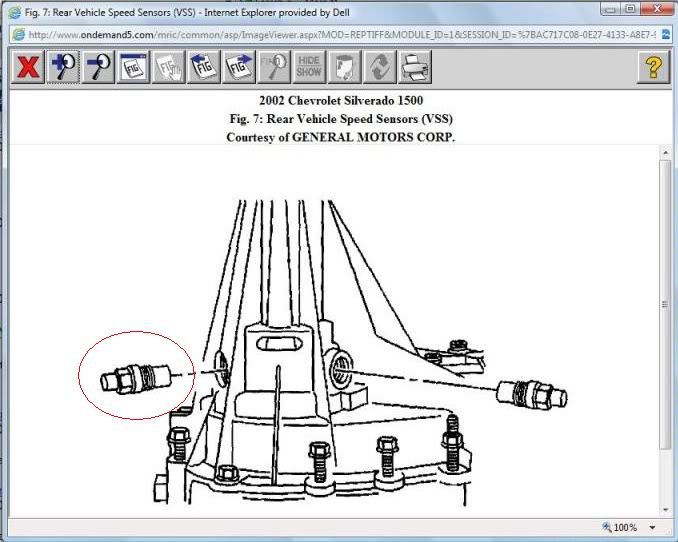
I'm assuming you have the NVG246. Here's a pic, Mitchell says the VSS for speedometer is on the left rear of the t-case.
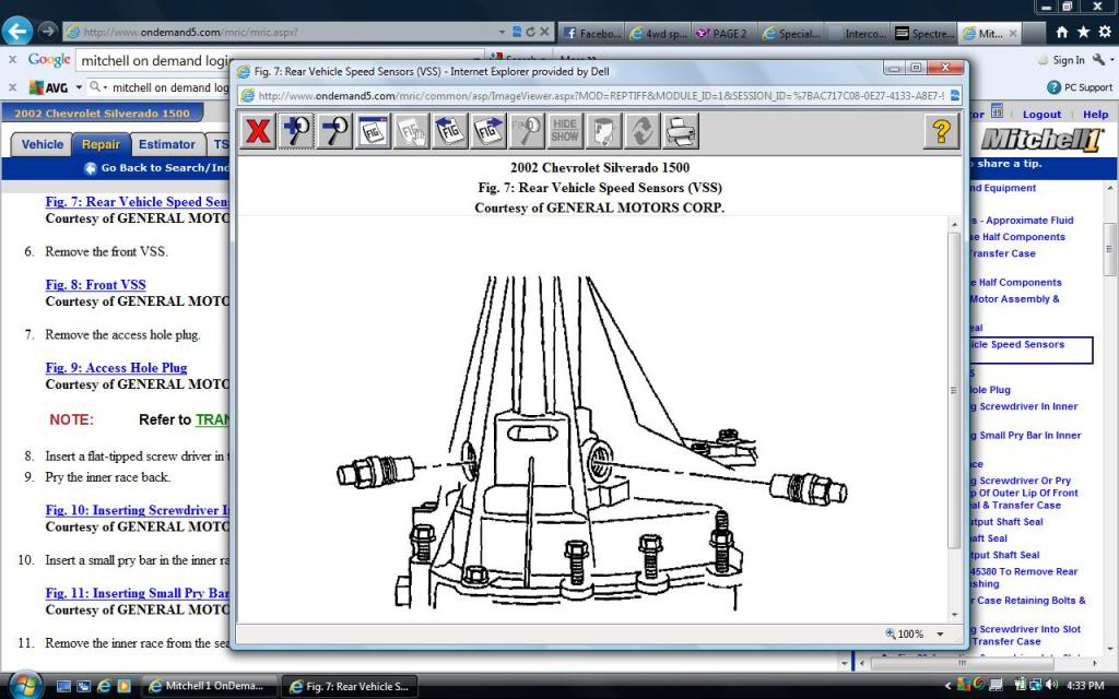
If you have a different case, lemme know. But it should still be on the left rear.
If you have a different case, lemme know. But it should still be on the left rear.
Jun 26, 2011 | 08:51 PM
#3

On the drivers side of the trans there are two sensors. One is the turbine or input speed sensor in the front of the case. The rear one is the output or VSS. The thing is that most factory 4x4 80's will have a plug here and there will not be VSS rotor on the rear planet. IN this case the reading is taken from the transfer case. HTH Vince
Jun 27, 2011 | 07:29 AM
#4
I thought it was this one... but you're/Mitchell is saying that both of them are speed sensors? Is it possible that dropping the t-case jarred the sensors enough to damage them? I wouldn't think it would, but I guess it may be possible.
Does anyone know if both sensors are required or if one is just a backup?
Those were the two plugs I was fairly certain I got the pins back in.

On the drivers side of the trans there are two sensors. One is the turbine or input speed sensor in the front of the case. The rear one is the output or VSS. The thing is that most factory 4x4 80's will have a plug here and there will not be VSS rotor on the rear planet. IN this case the reading is taken from the transfer case. HTH Vince
This is on a 60e. The input speed sensor is the one that is a PITA to unhook compared to the other two.
Last edited by dmelvin; Jun 27, 2011 at 07:37 AM.
Jun 27, 2011 | 04:36 PM
#5
As far as I know, the one on the driver's side is for VSS signal.
The one on the right rear is used for the automatic transfer case TCCM. The TCCM compares front prop shaft speed to rear prop shaft speed, and uses that information to apply the clutches in the t-case.
The one on the right rear is used for the automatic transfer case TCCM. The TCCM compares front prop shaft speed to rear prop shaft speed, and uses that information to apply the clutches in the t-case.
Jul 8, 2011 | 06:58 PM
#6
Changed sensor and have new plugs installed... Still no speedo... Any other ideas?
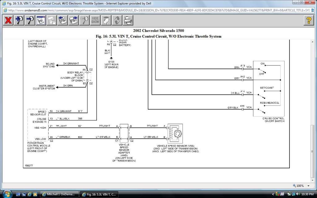
EDIT : Does anyone know where I can get a wiring diagram for the VSS from the PCM all the way back to the T-case? Or does anyone have one they can email me. I'm thinking broken/shorted wire now.
If I were to put 12V on pins RED 20/21 at the PCM harness, would I have the 12V back at the plug? Or does it go into a harness somewhere? Is it fused somewhere? I'm just trying to figure out the best way to troubleshoot this. I've tried reversing polarity on my new plug as well, so I know it doesn't matter what way I hooked it up, it still didn't work.
EDIT : Does anyone know where I can get a wiring diagram for the VSS from the PCM all the way back to the T-case? Or does anyone have one they can email me. I'm thinking broken/shorted wire now.
If I were to put 12V on pins RED 20/21 at the PCM harness, would I have the 12V back at the plug? Or does it go into a harness somewhere? Is it fused somewhere?
Last edited by dmelvin; Jul 8, 2011 at 11:40 PM.
Trending Topics
 Jul 9, 2011 | 12:29 PM
#9
That was just what I needed... looking at this, had it fixed in 30 minutes. Unwrapped the factory tape and loom. Lo and Behold, I had 2 of the sensors plugged into each other, the VSS and the other one on the front prop shaft speed, and then I had the PCM looped back to itself with the converter plug.
Couldn't have done it without ya man, if you ever make it to Missouri, I owe you several beers.
Couldn't have done it without ya man, if you ever make it to Missouri, I owe you several beers.
