
4l80E Rebuild Thread

 Aug 1, 2007 | 10:24 PM
#32

Thread Starter
TECH Regular
Joined: Aug 2006
Posts: 458
Likes: 0
From: Allen, TX
Allright, back on track. 
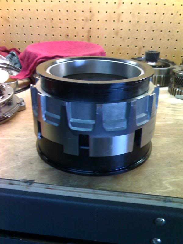
Now it's time to tackle the 4th drum.
seems harmless enough all torn apart.
I tried installing the 4th piston without the installer tool. After trying to get it in for 30 mins or so I tore a lip seal. So I decided to buy the 4th clutch lip seal installer (about $150).
Installation is much easier with the seal protector. you just stack them up like this and push down on the housing to install the piston.
Then remove the top piece and install the return spring assembly.
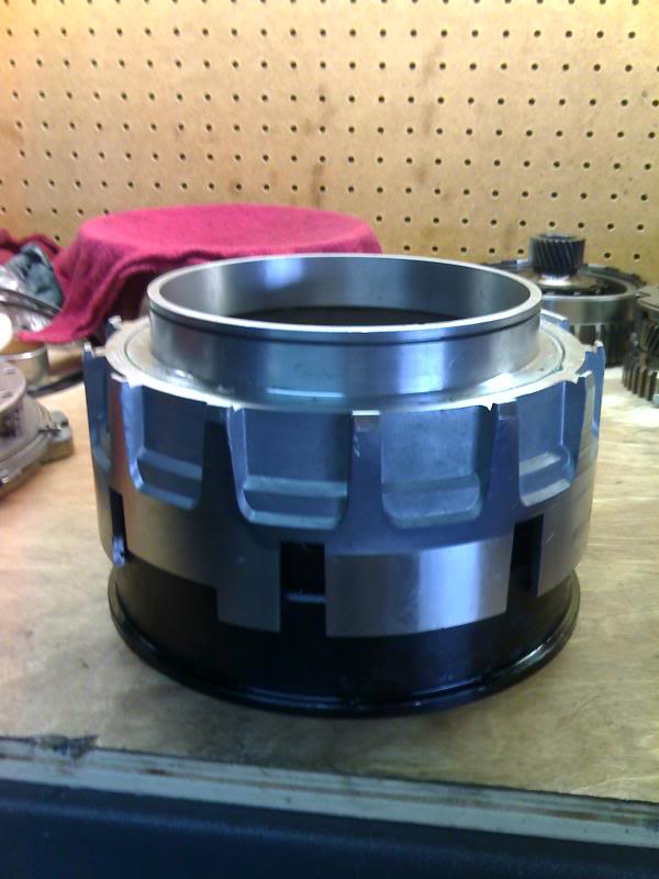
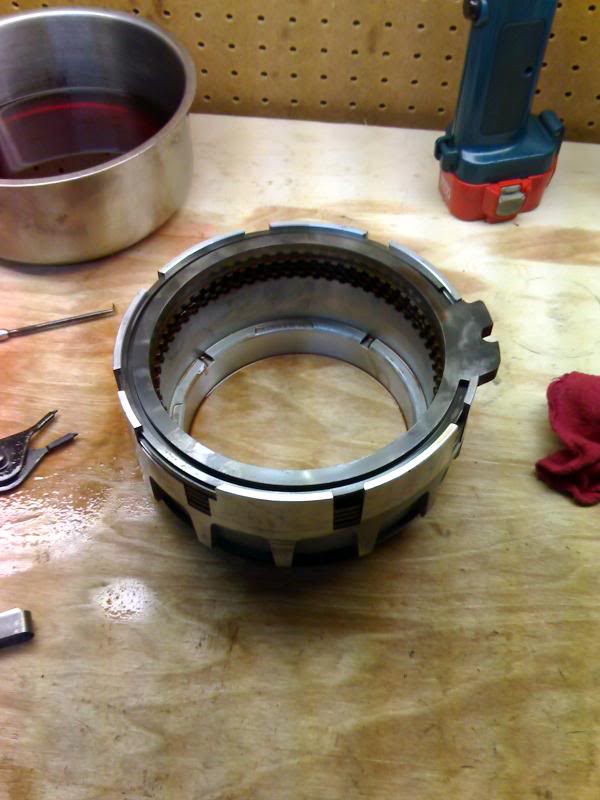
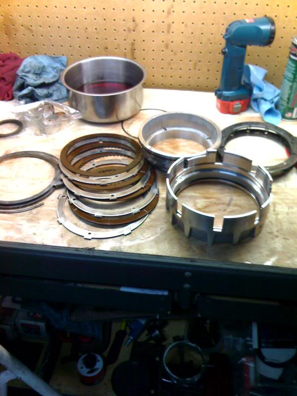
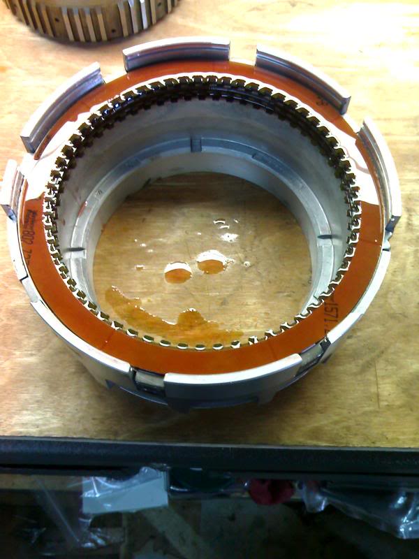
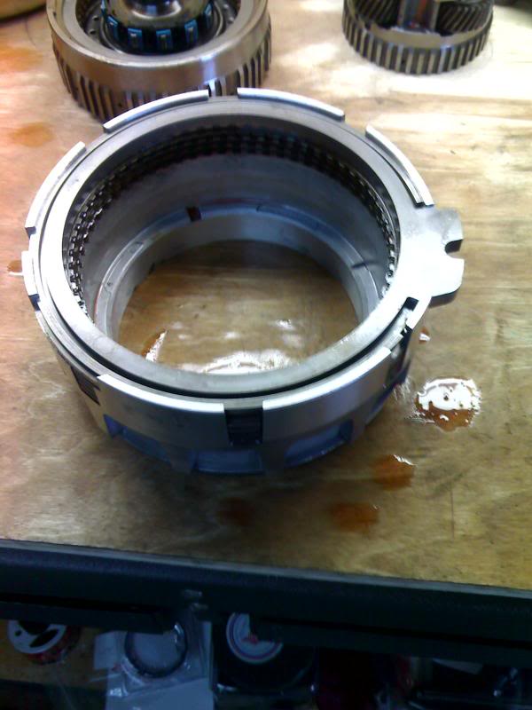
Next install the clutches and backing plate. Currently there are no Alto Red Eagle clutches for the 4th and overrun clutches. I used Borg Warner High energy. Clearence is .040"-100"
Now it's time to tackle the 4th drum.
seems harmless enough all torn apart.
I tried installing the 4th piston without the installer tool. After trying to get it in for 30 mins or so I tore a lip seal. So I decided to buy the 4th clutch lip seal installer (about $150).
Installation is much easier with the seal protector. you just stack them up like this and push down on the housing to install the piston.
Then remove the top piece and install the return spring assembly.
Next install the clutches and backing plate. Currently there are no Alto Red Eagle clutches for the 4th and overrun clutches. I used Borg Warner High energy. Clearence is .040"-100"
Aug 1, 2007 | 10:51 PM
#33
Thread Starter
TECH Regular
Joined: Aug 2006
Posts: 458
Likes: 0
From: Allen, TX
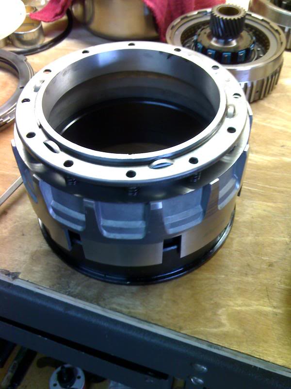
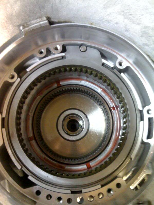
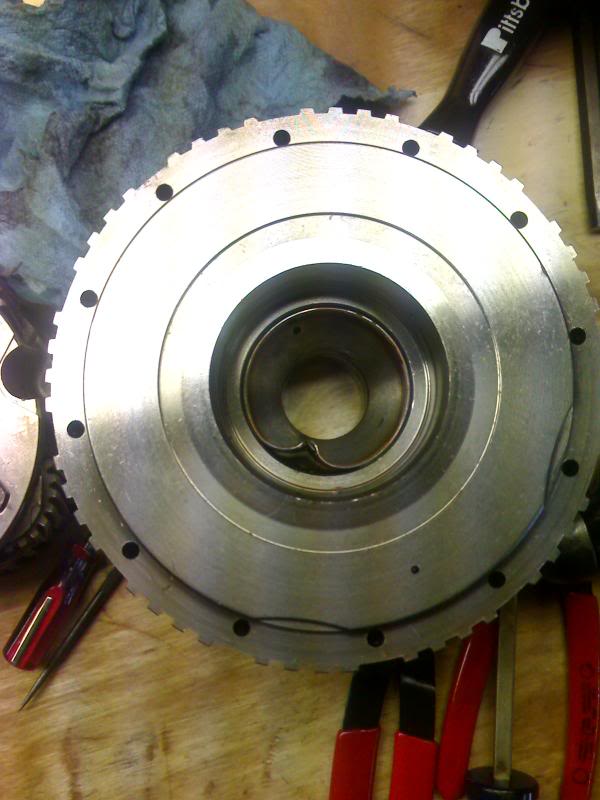
Install the 4th drum in the case in this position.
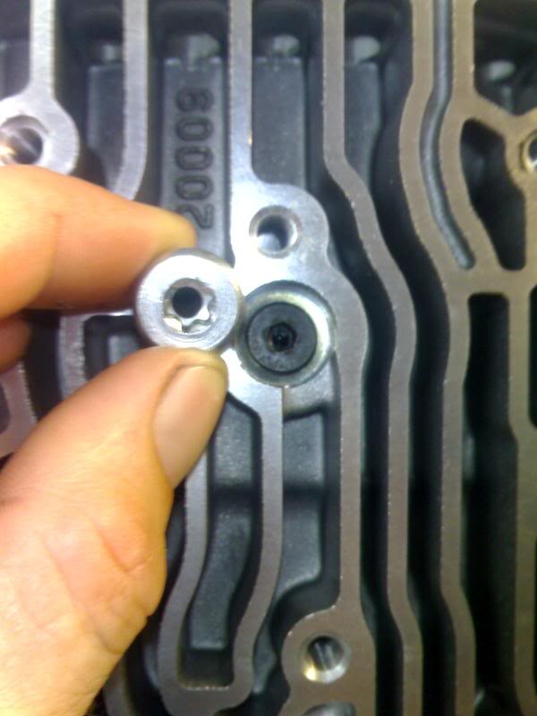
The Transgo shift kit has a 4th clutch bolt with a smaller orifice. Transgo bolt installed, stock bolt on left. Torque to 12 ft lbs.
You can air check the 4th clutch piston through the 4th clutch bolt.
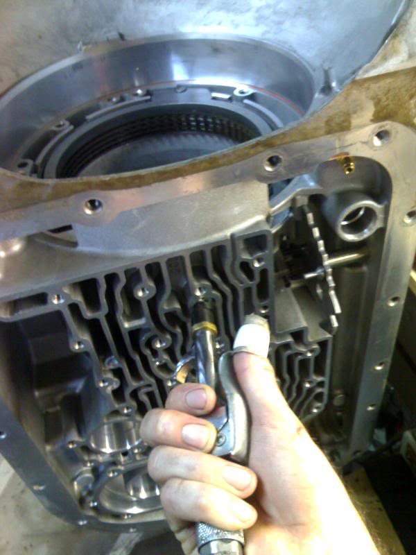
BTW I cut the out of my thumb when my hand slipped installing the 4th clutch return spring.
The Transgo shift kit has a 4th clutch bolt with a smaller orifice. Transgo bolt installed, stock bolt on left. Torque to 12 ft lbs.
You can air check the 4th clutch piston through the 4th clutch bolt.
BTW I cut the
out of my thumb when my hand slipped installing the 4th clutch return spring.
Aug 1, 2007 | 11:31 PM
#34
Thread Starter
TECH Regular
Joined: Aug 2006
Posts: 458
Likes: 0
From: Allen, TX
Now for the overhaul assembly.
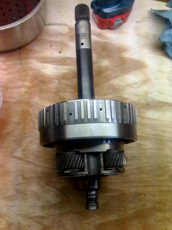
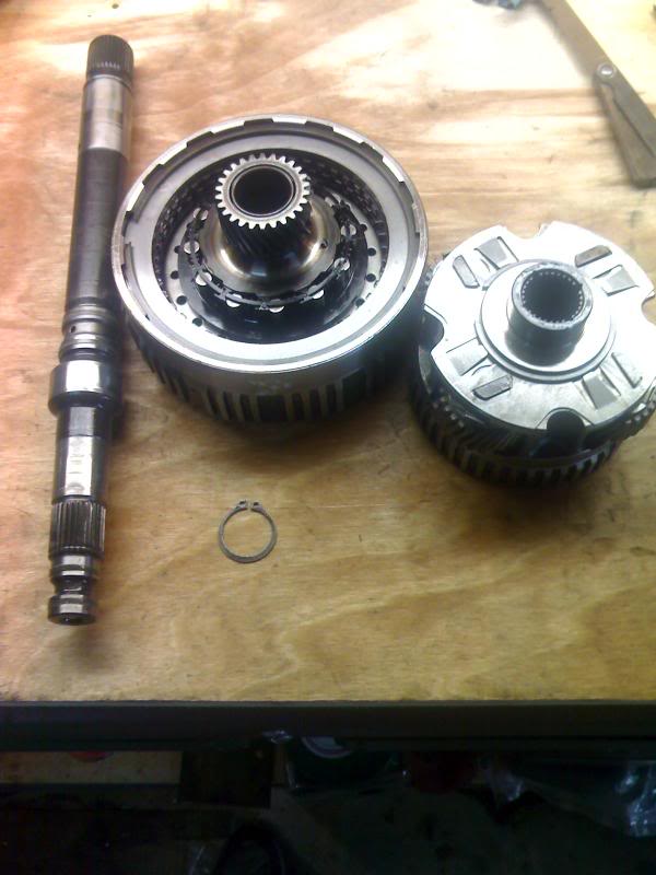
Remove the snap ring and seperate the turbine shaft, planetaries and overdrive drum.
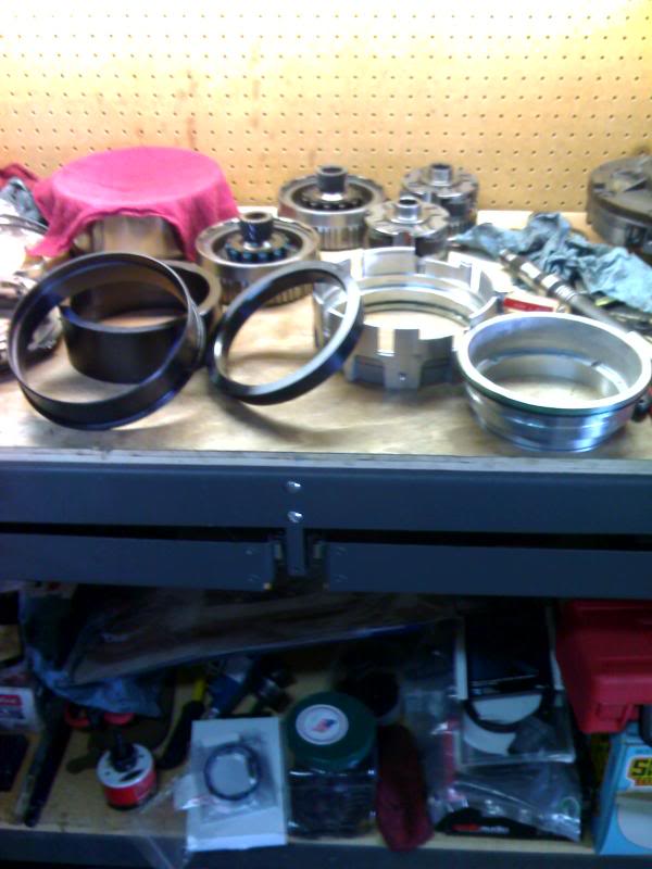
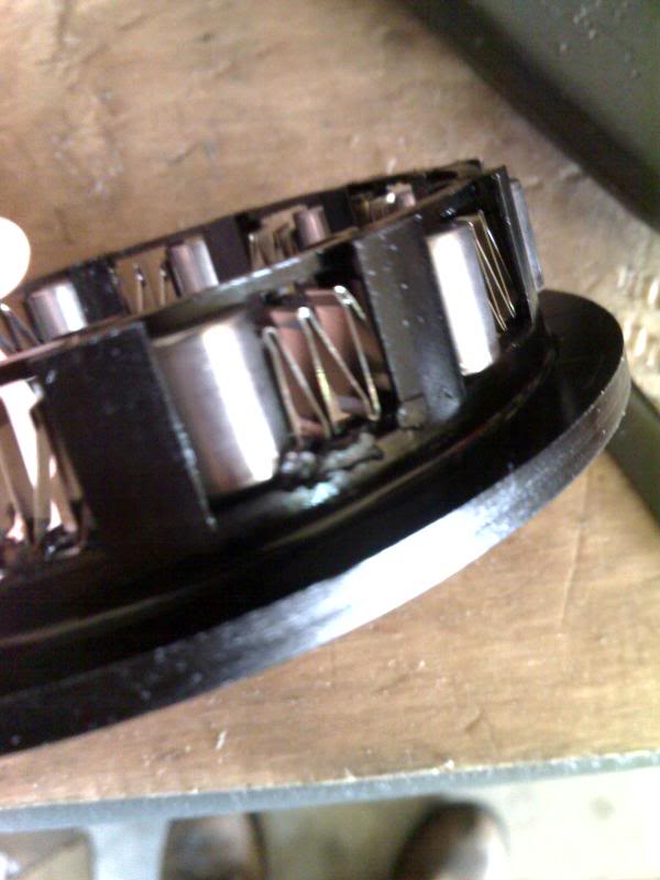
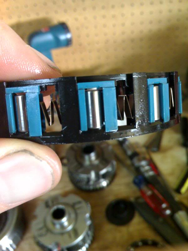
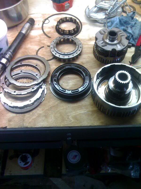
OK starting March of '01 GM updated the overdrive assembly because the rollers in the roller clutch could skew. Mine was the earlier style ('01 & earlier) and some of the rollers were skewed and lodged in the roller clutch so I decided this update would be a good Idea. You have to replace the overrun clutch housing , return spring, snap ring, planetaries, and overrun roller clutch. Both are pictured below the newer style can be identified by the blue inserts in the roller clutch.
YOU MUST REPLACE ALL THESE PARTS FOR THE UPDATE. AS WELL AS ENSURE YOU HABE A 2nd DESIGN TURBINE SHAFT.
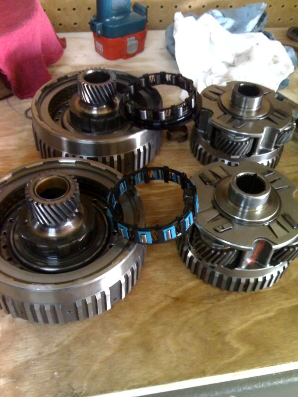
First design roller clutch. You can see where the roller had dug into the plastic ring.
Here's the new design roller clutch. notice the rollers are smaller and the inserts keep them straight.
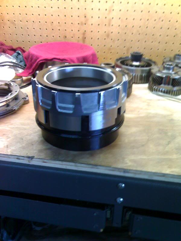
Tearing down the overrun drum is not much different although I needed smaller clamps.
when replacing the bushings I was able to split it at the seam.
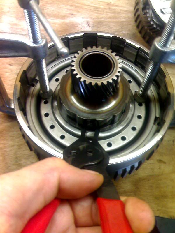
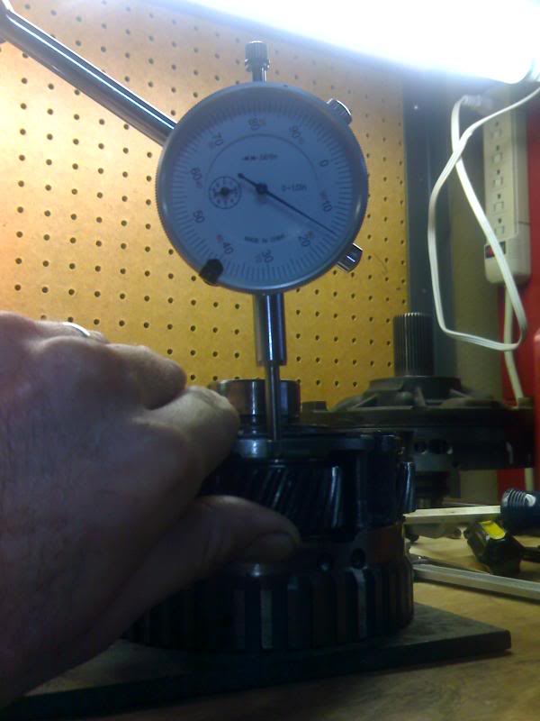
To check the pinion end play I stuck the carrier on my 4" wide piece of steel and attatched my dial indicator w/ magnetic base. (.009"-.024")
I replaced the bonded piston and the friction clutches (borg warner) and reused the steels.Clearance is .033"-.094".
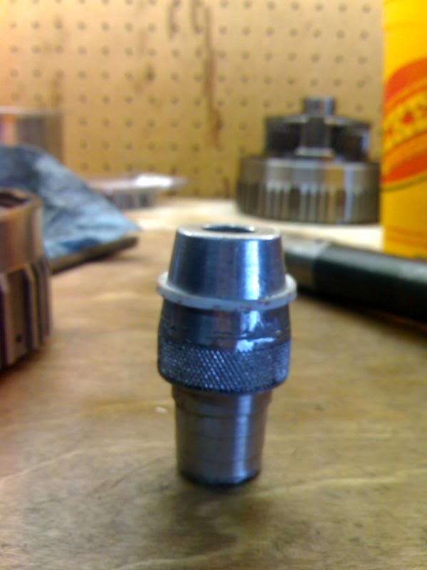
To stretch the teflon seals for the turbine shaft I used the cone tip from a standard trans clutch alignment tool.
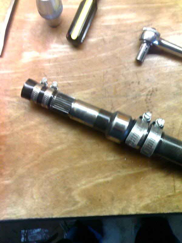
To resize them I used a piece of plastic cut from a spray can lid and some hose clamps. (That was a great tip from the other 4l80e thread I posted a link to earlier)
Assemble the parts and snap ring and lower the assembly holding it by the turbine shaft into the 4th clutches. Rotate it to make sure all the clutches are engaged and the drum is seated properly. The drum should sit slightly lower than the 4th clutch backing plate.
Remove the snap ring and seperate the turbine shaft, planetaries and overdrive drum.
OK starting March of '01 GM updated the overdrive assembly because the rollers in the roller clutch could skew. Mine was the earlier style ('01 & earlier) and some of the rollers were skewed and lodged in the roller clutch so I decided this update would be a good Idea. You have to replace the overrun clutch housing , return spring, snap ring, planetaries, and overrun roller clutch. Both are pictured below the newer style can be identified by the blue inserts in the roller clutch.
YOU MUST REPLACE ALL THESE PARTS FOR THE UPDATE. AS WELL AS ENSURE YOU HABE A 2nd DESIGN TURBINE SHAFT.
First design roller clutch. You can see where the roller had dug into the plastic ring.
Here's the new design roller clutch. notice the rollers are smaller and the inserts keep them straight.
Tearing down the overrun drum is not much different although I needed smaller clamps.
when replacing the bushings I was able to split it at the seam.
To check the pinion end play I stuck the carrier on my 4" wide piece of steel and attatched my dial indicator w/ magnetic base. (.009"-.024")
I replaced the bonded piston and the friction clutches (borg warner) and reused the steels.Clearance is .033"-.094".
To stretch the teflon seals for the turbine shaft I used the cone tip from a standard trans clutch alignment tool.
To resize them I used a piece of plastic cut from a spray can lid and some hose clamps. (That was a great tip from the other 4l80e thread I posted a link to earlier)
Assemble the parts and snap ring and lower the assembly holding it by the turbine shaft into the 4th clutches. Rotate it to make sure all the clutches are engaged and the drum is seated properly. The drum should sit slightly lower than the 4th clutch backing plate.
Aug 23, 2007 | 09:25 PM
#35
Thread Starter
TECH Regular
Joined: Aug 2006
Posts: 458
Likes: 0
From: Allen, TX
Well I've been on vacation for a couple of weeks and now it's time to finish this thread. Tranmission is built I just need the time to install it.
Next comes the pump.
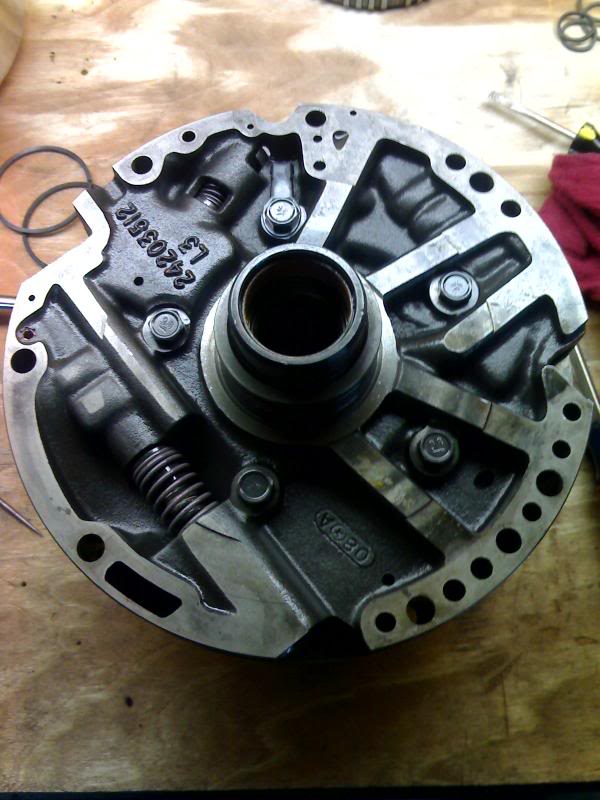
Here are the 2 halves seperated.
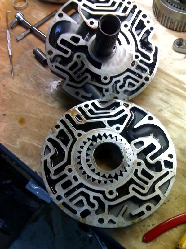
I basically just disassembled, cleaned and inspected the pump. The transgo shift kit does have you make some modifications to the pump, but I forgot to take pictures and the transgo instructions are pretty clear on those.
The boost valve, bushing, and springs are changed with the transgo HD2 shift kit.
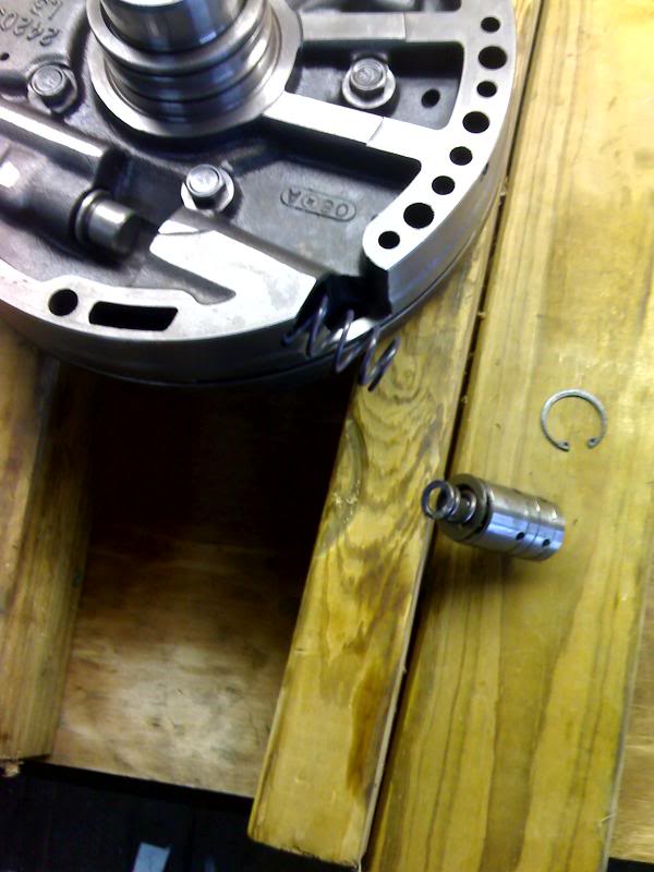
I used 2 big hose clamps to make a pump alignment tool. I'm sure you could get one clamp that was big enough, but these were readily available at Home Depot. I planned on buying the proper alignment tool, but a generic one was about $150.00 . That seems to be the magic $$$ for transmission tools.
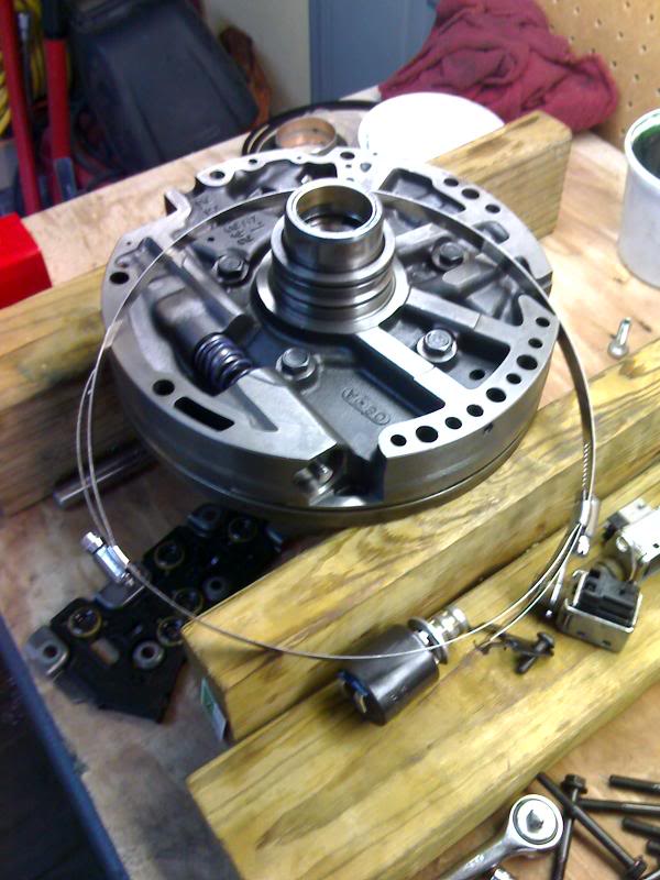
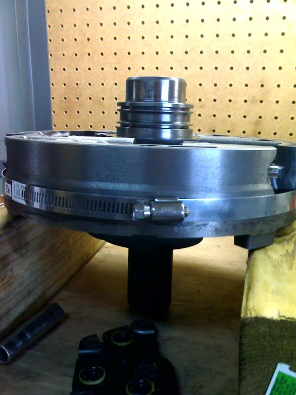
Pump installed and torqued to 18 ft. lbs.
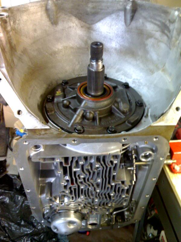
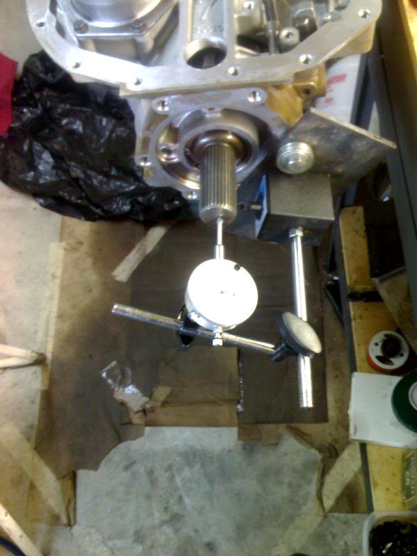
Next I checked the end play. This was alittle tough because all the new bushings made everything fit pretty snug. I basically had to push down on the turbine shaft, then set the dial indicator. Then I pulled up on the turbine shaft as I rotated it.
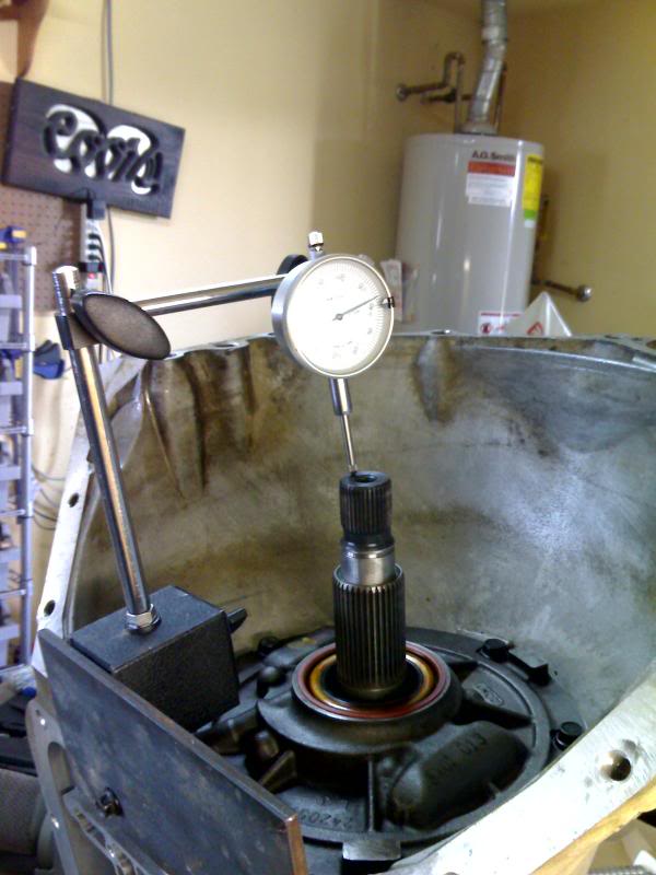
Checking rear end play ( I used the same steel plate for all the end play measurements. )
Next comes the pump.
Here are the 2 halves seperated.
I basically just disassembled, cleaned and inspected the pump. The transgo shift kit does have you make some modifications to the pump, but I forgot to take pictures and the transgo instructions are pretty clear on those.
The boost valve, bushing, and springs are changed with the transgo HD2 shift kit.
I used 2 big hose clamps to make a pump alignment tool. I'm sure you could get one clamp that was big enough, but these were readily available at Home Depot. I planned on buying the proper alignment tool, but a generic one was about $150.00
. That seems to be the magic $$$ for transmission tools.Pump installed and torqued to 18 ft. lbs.
Next I checked the end play. This was alittle tough because all the new bushings made everything fit pretty snug. I basically had to push down on the turbine shaft, then set the dial indicator. Then I pulled up on the turbine shaft as I rotated it.
Checking rear end play ( I used the same steel plate for all the end play measurements. )
Aug 23, 2007 | 09:35 PM
#36

Is pump halves alignment criticial? Or is it so it will slide into the housing? Nice clamp idea... maybe add some sheet metal from Home Depot and wrap the pump and then put on the clamps? Anything I can do not to spend money on special tools except when absolutely necessary... I'm all for 
Great work!
Bill
Great work!
Bill
 Aug 23, 2007 | 09:59 PM
#38
Thread Starter
TECH Regular
Joined: Aug 2006
Posts: 458
Likes: 0
From: Allen, TX
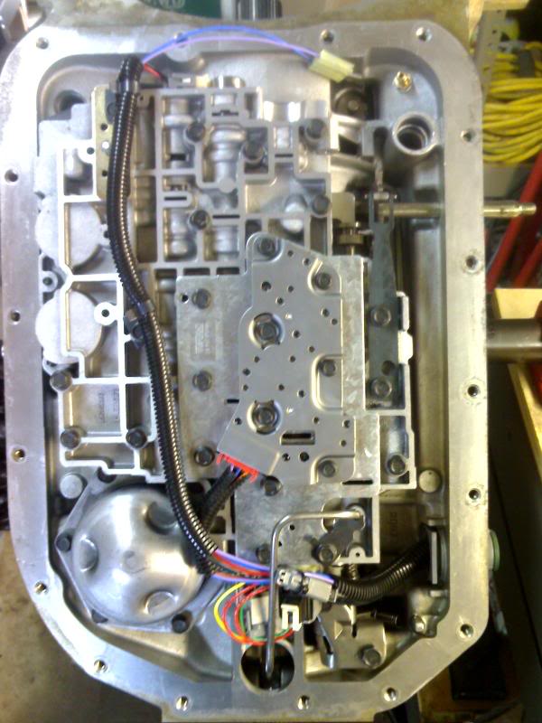
Here's the valvebody ready for cleaning and modifications.
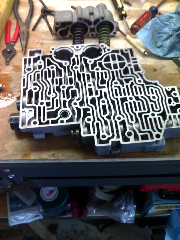
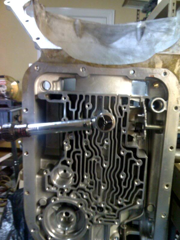
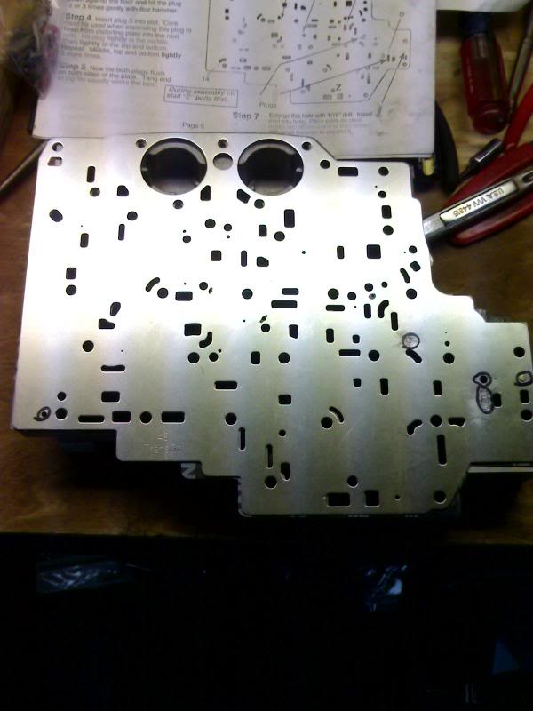
Here's a pic of the seperator plate with some of the modified holes marked. Some get drilled larger and some get plugged and peened shut.
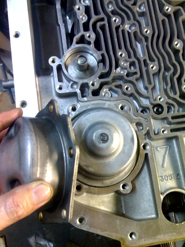
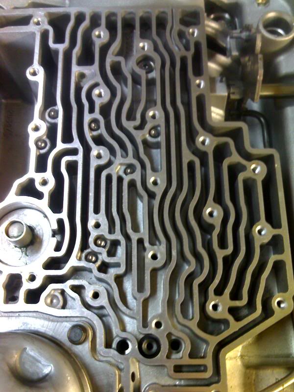
1-2 servo installed. Cover going on reverse servo and 1-2 accumulator. I did not check the pin lengths because the old bands and drums seemed fine and I am using stock sized carbon lined bands.(that would also require a special tool)
The Transgo shift kit has you leave out one of the check *****. 7 of the original 8 installed.
Here's the valvebody, pressure manifold switch, and new internal harness installed.
Here are the guts of the transgo vacuum modulator kit.
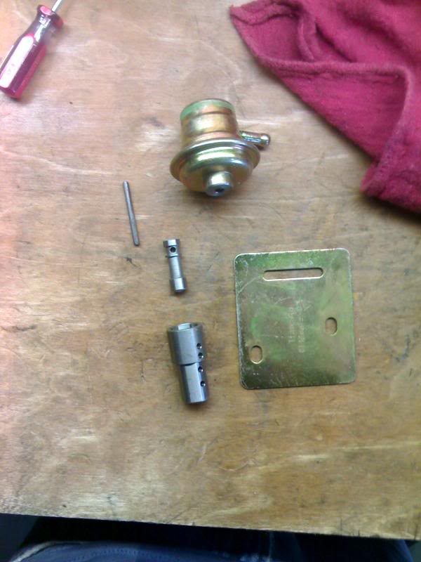
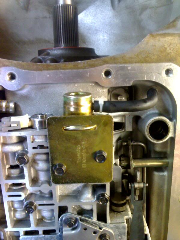
And here 's the vacuum modulator installed. This takes the place of the variable force motor, which controls line pressure.
Here's a pic of the seperator plate with some of the modified holes marked. Some get drilled larger and some get plugged and peened shut.
1-2 servo installed. Cover going on reverse servo and 1-2 accumulator. I did not check the pin lengths because the old bands and drums seemed fine and I am using stock sized carbon lined bands.(that would also require a special tool)
The Transgo shift kit has you leave out one of the check *****. 7 of the original 8 installed.
Here's the valvebody, pressure manifold switch, and new internal harness installed.
Here are the guts of the transgo vacuum modulator kit.
And here 's the vacuum modulator installed. This takes the place of the variable force motor, which controls line pressure.
Sep 15, 2007 | 03:39 PM
#40
Thread Starter
TECH Regular
Joined: Aug 2006
Posts: 458
Likes: 0
From: Allen, TX
Yeah! As a matter of fact the trans is in and runnin. The 2800 vig triple disc is a nice addition as well. Right now at WOT the shifts are WAY too hard. It feels like somethig is slamming into the pack of the truck. The TCC is even harder. part throttle shifts are ok. I think I need to shorten the pin on the vacuum modulator. I'm running the longest length Transgo reccomends 1.345 (says for commercial/ working trucks). Transgo says to shorten if shifts are too hard.
My line pressure ranges from about 75 psi at 20 inhg to 200 at 0 inhg. At WOT the pressure gauge fluctuates around 200psi so I'm pretty sure that's the pressure regulator doing it's job. Transgo said pressure ranges should be between 80-200psi. The stock pressure chart for an EPC (force motor) shows 177psi at .02 amps as the max. I'm pretty sure shortening the pin will solve my problems. I plan on taking care of that today.
My line pressure ranges from about 75 psi at 20 inhg to 200 at 0 inhg. At WOT the pressure gauge fluctuates around 200psi so I'm pretty sure that's the pressure regulator doing it's job. Transgo said pressure ranges should be between 80-200psi. The stock pressure chart for an EPC (force motor) shows 177psi at .02 amps as the max. I'm pretty sure shortening the pin will solve my problems. I plan on taking care of that today.

