


STS Oil Pump, how to wire it??

 Mar 29, 2009 | 12:30 PM
#23

TECH Addict
Joined: Feb 2004
Posts: 2,120
Likes: 0

I think the switch by the return pump opens at 3 psi if the oil is backing up and completes a circuit to ground. This sets off the warning buzzer to let you know there is a problem returning the oil to the engine.
The switch on the manifold opens at 1 psi boost and puts the pump on high speed and vents the crankcase to the atmosphere so boost does not build up in the crankcase. It also completes a ground circuit. You can wire a switch in the cab through it to put the pump on high speed if you live in cold climates to keep cold oil from backing up when not in boost or if you want control over the pump.
The switch on the manifold opens at 1 psi boost and puts the pump on high speed and vents the crankcase to the atmosphere so boost does not build up in the crankcase. It also completes a ground circuit. You can wire a switch in the cab through it to put the pump on high speed if you live in cold climates to keep cold oil from backing up when not in boost or if you want control over the pump.
 Mar 29, 2009 | 08:44 PM
#26
Thread Starter
TECH Resident
iTrader: (3)
Joined: Oct 2008
Posts: 771
Likes: 0
From: Independence, VA
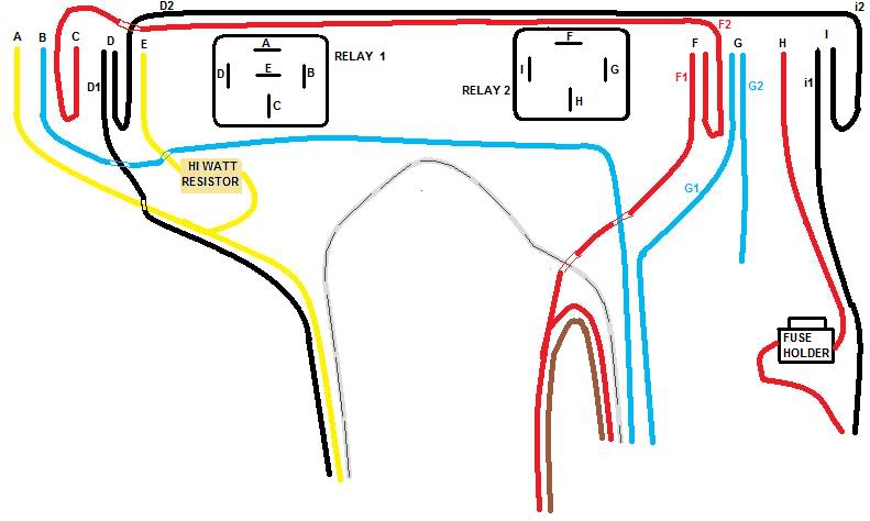
I take it that A and E are the hot to the pump and D1 is the ground for the pump and the oil pressure switch.
The unlabled white wire in the middle runs from the oil pressure switch to the in cab buzzer.
H and i1 are the main power and ground.
Tell me if I am wrong or not so far.
The unlabled white wire in the middle runs from the oil pressure switch to the in cab buzzer.
H and i1 are the main power and ground.
Tell me if I am wrong or not so far.
Last edited by Ender06; Mar 29, 2009 at 10:37 PM.
Mar 30, 2009 | 07:18 PM
#28
TECH Addict
Joined: Feb 2004
Posts: 2,120
Likes: 0
H = Fused lead connect to positive terminal block by alternator.
i1 = ground connect to stud on firewall near brake booster (short black wire?)
A & E = yellow wire goes to terminal at outlet side of pump, marked (-) on top of pump. Careful pump can run in either direction!
D1 = black wire to terminal at inlet to pump , marked (+) on top of pump.
Pressure switch wires are separate.
There is a spare green wire in harness to rear. I used it to power my boost controller.
There is a ground strap - attach to frame rail near pump.
i1 = ground connect to stud on firewall near brake booster (short black wire?)
A & E = yellow wire goes to terminal at outlet side of pump, marked (-) on top of pump. Careful pump can run in either direction!
D1 = black wire to terminal at inlet to pump , marked (+) on top of pump.
Pressure switch wires are separate.
There is a spare green wire in harness to rear. I used it to power my boost controller.
There is a ground strap - attach to frame rail near pump.