
Magnavolt/boost a pump flow increase?


 Mar 9, 2006 | 08:33 AM
#12

Thread Starter
TECH Senior Member
iTrader: (6)
Joined: Jul 2005
Posts: 5,257
Likes: 0
From: Decatur, AL
The pump signal wire should be the grey wire in the bundle coming out of the fuse box and running down the frame rail. I think it is the same main power wire that supplies the pump. Not sure though.
Mar 9, 2006 | 10:03 AM
#13

TECH Addict
Joined: Feb 2004
Posts: 2,120
Likes: 0
Originally Posted by mjhoward
The pump signal wire should be the grey wire in the bundle coming out of the fuse box and running down the frame rail. I think it is the same main power wire that supplies the pump. Not sure though.
Mar 9, 2006 | 04:27 PM
#14
Thread Starter
TECH Senior Member
iTrader: (6)
Joined: Jul 2005
Posts: 5,257
Likes: 0
From: Decatur, AL
Originally Posted by Mort
I would only use the grey fuel pump signal wire if you are going to run it to switch a relay which will then supply power to the pump booster. The grey wire is a signal wire only and is not meant to supply power directly to the fuel pump(s). It should be used to signal the inline fuel pump through a relay in the first place though and can be used the same way with the booster but a relay will need to be added to the booster install.
Mar 9, 2006 | 06:47 PM
#15
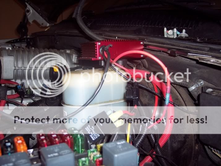
I talked to Blown364 today. He has done this install. He told me to disconnect the red wire from the RELAY that is already powering the inline pump. Cut the spade off that wire and connect it to the 12 gauge red wire on the boost a pump with the fuse. Next, take the smaller wire I just cut the spade off of (the red wire to the pump) and connect it to the other 12 gauge boost a pump red wire. Ground to ground, and connect the other two wires to the hobbs. Testing will begin in a few minutes. We are on a dinner break. Picture is hard to see. Let me know what you think...
Mar 9, 2006 | 07:31 PM
#16

Looks right to me.
Before you button it all up start the truck up to make sure the pump is running.
Then connect the hobb switch wires together to test the pump. You will hear it speed up as it should.
Let us know how it turns out
Before you button it all up start the truck up to make sure the pump is running.
Then connect the hobb switch wires together to test the pump. You will hear it speed up as it should.
Let us know how it turns out
Originally Posted by 1SlowHoe
I talked to Blown364 today. He has done this install. He told me to disconnect the red wire from the RELAY that is already powering the inline pump. Cut the spade off that wire and connect it to the 12 gauge red wire on the boost a pump with the fuse. Next, take the smaller wire I just cut the spade off of (the red wire to the pump) and connect it to the other 12 gauge boost a pump red wire. Ground to ground, and connect the other two wires to the hobbs. Testing will begin in a few minutes. We are on a dinner break. Picture is hard to see. Let me know what you think...

Mar 9, 2006 | 08:06 PM
#17
Done! Took it for a quick 0-60 and 15-80 run and the needle sat at 60 like a rock. I also did a voltage check before I ran it. Went from 12.6V to 16.4. This was at idle using a jumper between the terminals on the Hobbs switch. The best part was when I dropped off the throttle, it didn't do its usual drop into the 40's. It dropped to 50 and stopped. I'm happy now  Dyno tune tomorrow morning @ 0900. 2.75" pulley going on......Hopefully I won't blow anything up
SPECIAL THANKS TO Blown364 & BlownChevy for helping with the wiring.
Dyno tune tomorrow morning @ 0900. 2.75" pulley going on......Hopefully I won't blow anything up SPECIAL THANKS TO Blown364 & BlownChevy for helping with the wiring.


Thread
Thread Starter
Forum
Replies
Last Post
gaps
GMT 800 & Older GM General Discussion
10
Oct 15, 2015 02:53 PM
muncie21
Tuning, Diagnostics, Electronics, and Wiring
2
Sep 7, 2015 09:55 PM