
HOW TO: Replace knock sensors on a GMT800/GEN III V8
 Dec 7, 2010 | 01:29 PM
#1

Thread Starter

Joined: Nov 2009
Posts: 1,102
Likes: 1
From: Central NJ
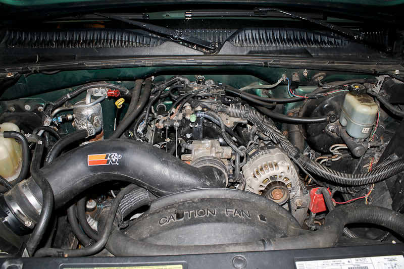
I know most on this site have gone much deeper into the engine bay than this, but I wrote it up on another site, and figured I'd post it here as well.
So right after my 6.0 swap last March, I came up with the code "P0332 - Knock sensor low input: sensor 2".
99% of the time on the GMT800 trucks, this code means that the knock sensor has gotten wet, corroded, and caused the sensor to malfunction. This happens because they sit in a recess in the valley cover, which tends to fill with water, causing the corrosion.
Parts to be replaced:
- Both front and rear knock sensors
- Knock sensor sub-harness
- Intake manifold gaskets
Tools you will need:
- 1/4" and 3/8" drive ratchets with assorted sockets
- Torque wrench
- Fuel line removal tool (I do not remember the sizes, but I can check when I'm home over winter break).
You will want to replace both knock sensors while you're in there, even if only one is bad, just so you don't have to pull it all apart again. You will also want to replace the knock sensor sub-harness that runs from the sensors to the main engine harness, since the harnesses like to corrode as well. The intake manifold gaskets are also a good idea to replace, though not always completely necessary. Use your discretion here.
On to the actual job. Basically we will be removing the intake manifold to gain access to the knock sensors.
It's not a bad idea to disconnect the battery before doing this, just to be safe.
The first step is to remove the intake tube. Pretty simple, just undo the hose clamps and any clips that may be attached to the tube if you still have the stock intake.
Next, remove the throttle cable and cruise control cable from the throttle body. If you have an '03 or newer truck, you will need to unplug the drive-by-wire harness.
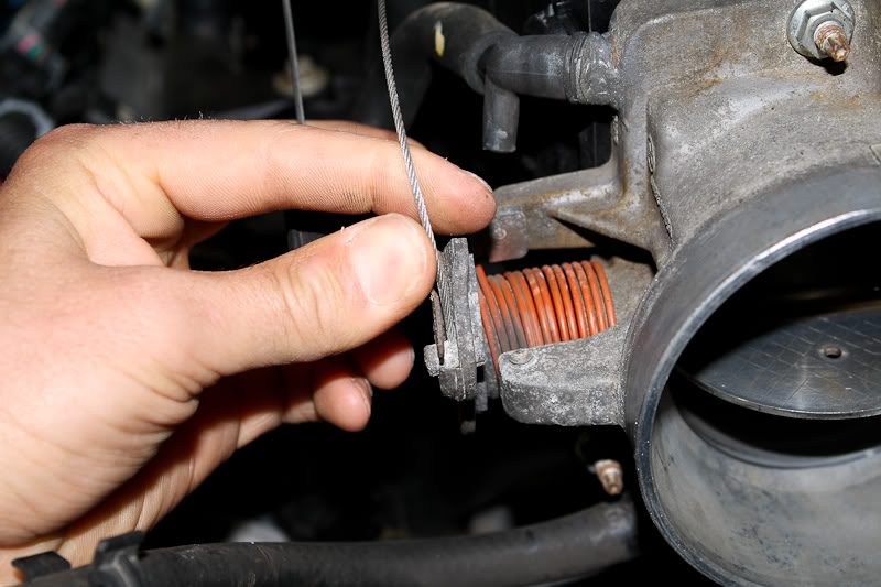
Next, remove the throttle cable brackets from the intake manifold, and hold the bracket and cables off to the side somehow. I just pinned mine under the cowl.
This second bracket also holds the engine harness in place.
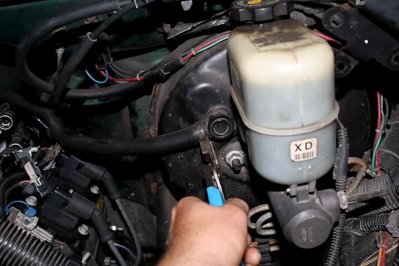
Unbolt the main engine harness bracket on the drivers side of the intake manifold.
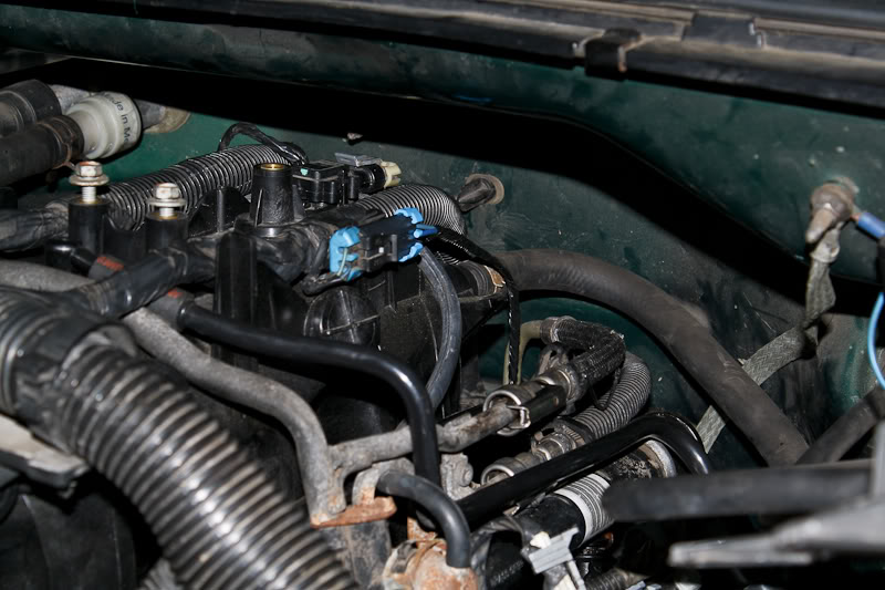
Next, you'll need to unplug some sensors.
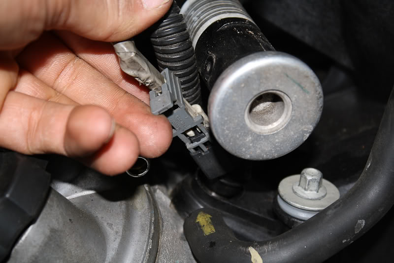
The EVAP solenoid:
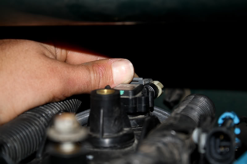
The MAP sensor:
And the knock sensor sub-harness mentioned above.
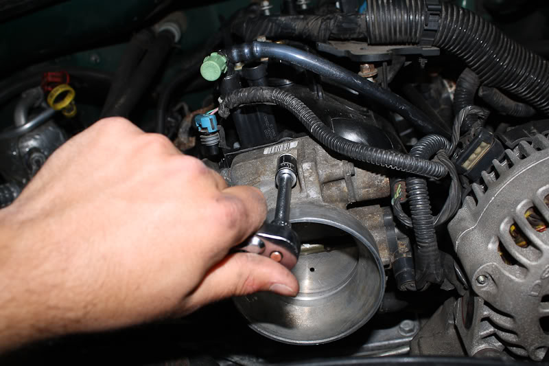
The intake manifold can be removed with the throttle body in place, but it is a pain in the *** to remove the small coolant hoses from the bottom of the TB, so I chose to just unbolt it from the manifold, and set it aside. Also kept me from needing to mess with the coolant system.
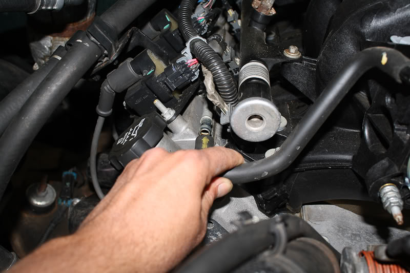
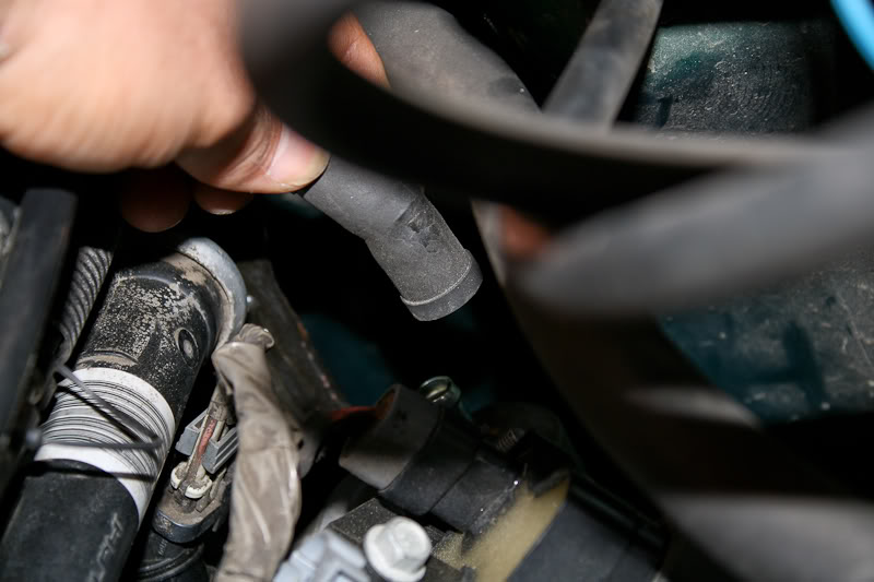
Next, remove the vent hoses that come off of each valve cover.
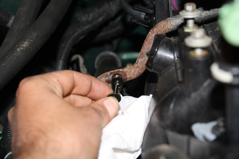
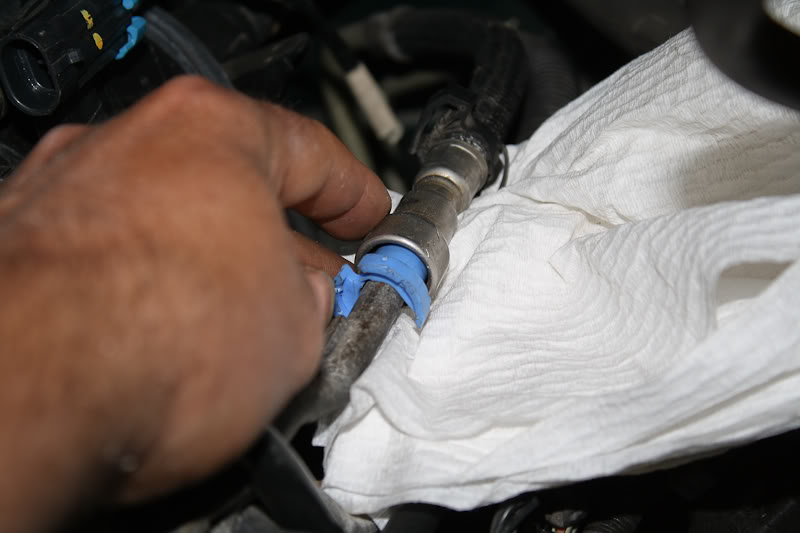
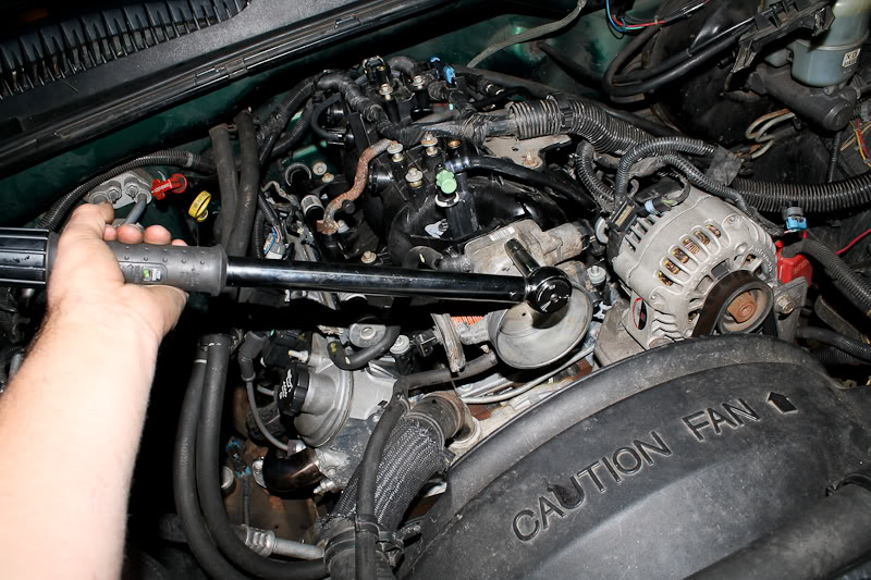
After that, relieve the fuel pressure via the schrader valve on the fuel rail crossover. Have a rag or small container ready to catch the gas.
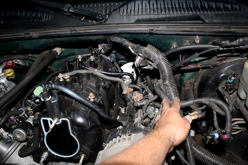
After relieving the pressure, using the fuel line removal tool, disconnect the fuel lines from the fuel rails at the back of the driver side of the intake manifold. '99-'03 trucks will have a supply, and a return line, while '04+ trucks do not have a return line. Again, keep a rag/container handy to catch the gas. The EVAP line also has a connection between the engine and firewall that needs the fuel line removal tool. You can't see it, but feel around for it, and you should be able to find it.
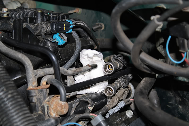
After that, unplug all 8 injectors. These connectors can be a bit tricky the first time, but just look at how they're constructed, and don't try to brute-force them off.
Disconnect the vacuum line from the brake booster. (If your truck has hydroboost brakes, you can skip this).
Pull the engine harness off to the side. Unplug the alternator, idle air control valve and throttle position sensor on the throttle body to do this.
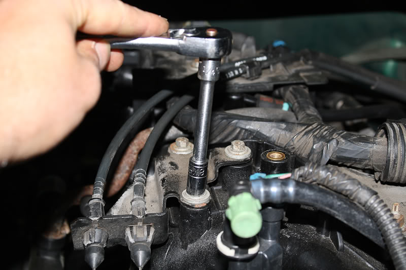
Now it's time to unbolt the intake manifold.
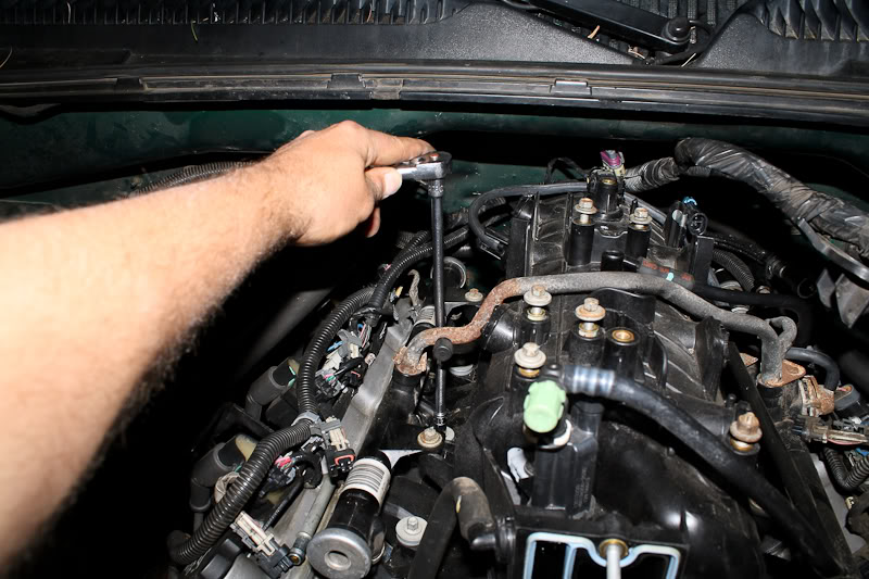
Technically, you're supposed to unbolt it in the reverse order of how you bolt it down, but I haven't had any problems just unbolting it any which way.

Double check to make sure nothing is attached to the intake manifold, and pull it off.
So right after my 6.0 swap last March, I came up with the code "P0332 - Knock sensor low input: sensor 2".
99% of the time on the GMT800 trucks, this code means that the knock sensor has gotten wet, corroded, and caused the sensor to malfunction. This happens because they sit in a recess in the valley cover, which tends to fill with water, causing the corrosion.
Parts to be replaced:
- Both front and rear knock sensors
- Knock sensor sub-harness
- Intake manifold gaskets
Tools you will need:
- 1/4" and 3/8" drive ratchets with assorted sockets
- Torque wrench
- Fuel line removal tool (I do not remember the sizes, but I can check when I'm home over winter break).
You will want to replace both knock sensors while you're in there, even if only one is bad, just so you don't have to pull it all apart again. You will also want to replace the knock sensor sub-harness that runs from the sensors to the main engine harness, since the harnesses like to corrode as well. The intake manifold gaskets are also a good idea to replace, though not always completely necessary. Use your discretion here.
On to the actual job. Basically we will be removing the intake manifold to gain access to the knock sensors.
It's not a bad idea to disconnect the battery before doing this, just to be safe.
The first step is to remove the intake tube. Pretty simple, just undo the hose clamps and any clips that may be attached to the tube if you still have the stock intake.
Next, remove the throttle cable and cruise control cable from the throttle body. If you have an '03 or newer truck, you will need to unplug the drive-by-wire harness.
Next, remove the throttle cable brackets from the intake manifold, and hold the bracket and cables off to the side somehow. I just pinned mine under the cowl.
This second bracket also holds the engine harness in place.
Unbolt the main engine harness bracket on the drivers side of the intake manifold.
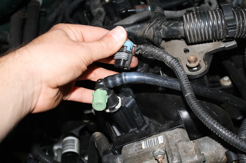
Next, you'll need to unplug some sensors.
The EVAP solenoid:
The MAP sensor:
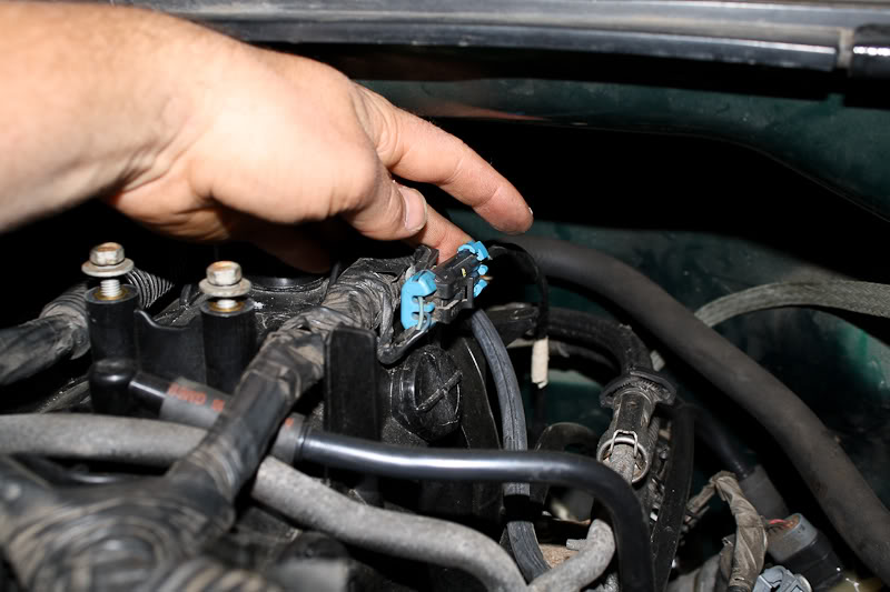
And the knock sensor sub-harness mentioned above.
The intake manifold can be removed with the throttle body in place, but it is a pain in the *** to remove the small coolant hoses from the bottom of the TB, so I chose to just unbolt it from the manifold, and set it aside. Also kept me from needing to mess with the coolant system.
Next, remove the vent hoses that come off of each valve cover.
After that, relieve the fuel pressure via the schrader valve on the fuel rail crossover. Have a rag or small container ready to catch the gas.
After relieving the pressure, using the fuel line removal tool, disconnect the fuel lines from the fuel rails at the back of the driver side of the intake manifold. '99-'03 trucks will have a supply, and a return line, while '04+ trucks do not have a return line. Again, keep a rag/container handy to catch the gas. The EVAP line also has a connection between the engine and firewall that needs the fuel line removal tool. You can't see it, but feel around for it, and you should be able to find it.
After that, unplug all 8 injectors. These connectors can be a bit tricky the first time, but just look at how they're constructed, and don't try to brute-force them off.
Disconnect the vacuum line from the brake booster. (If your truck has hydroboost brakes, you can skip this).
Pull the engine harness off to the side. Unplug the alternator, idle air control valve and throttle position sensor on the throttle body to do this.
Now it's time to unbolt the intake manifold.
Technically, you're supposed to unbolt it in the reverse order of how you bolt it down, but I haven't had any problems just unbolting it any which way.
Double check to make sure nothing is attached to the intake manifold, and pull it off.
Dec 7, 2010 | 01:29 PM
#2
Thread Starter
Joined: Nov 2009
Posts: 1,102
Likes: 1
From: Central NJ
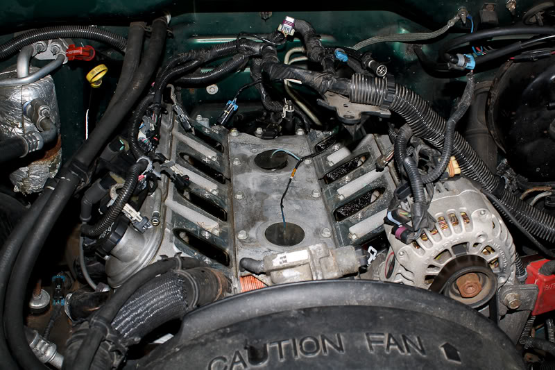
The knock sensors are located under those big black plugs. It's not a bad idea to keep a vacuum handy for this step, as lots of dirt/leaves/pine needles like to chill out under the manifold.
Remove the black plugs from the valley cover.
You can sort of see that my rear sensor was sitting in about 2" of water.
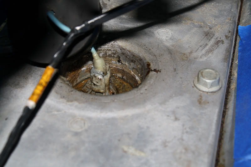
This is the corrosion on an engine with 25,000 miles:
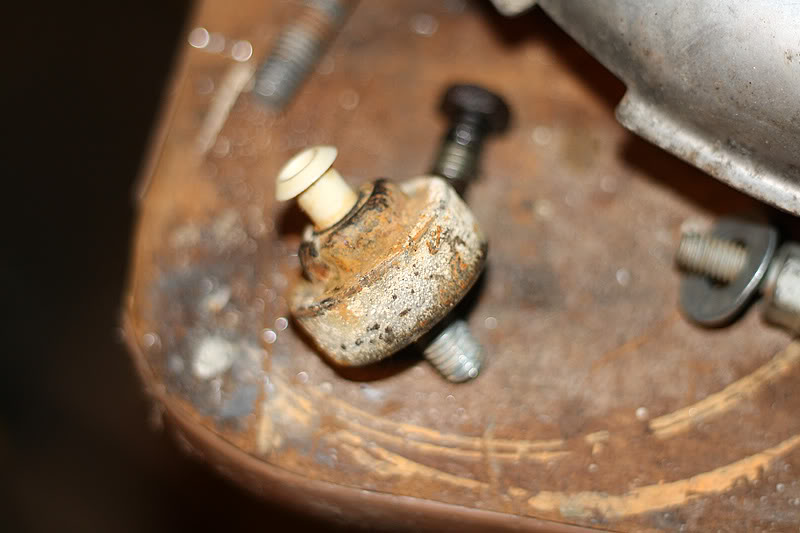
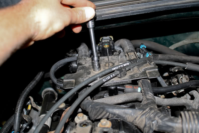
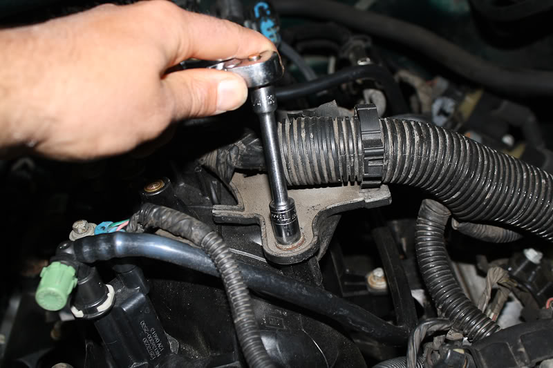
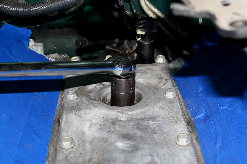
Unbolt both knock sensors, I believe they take a 22mm deep socket.
This is the most important step. Get your torque wrench, and torque the new knock sensors to EXACTLY 15 ft-lbs. If they are too tight, they will be over-sensitive, and if they are too loose they can cause false knock.
Next, take some RTV, and apply it to the rubber plugs to seal off the holes. This is how I applied it:
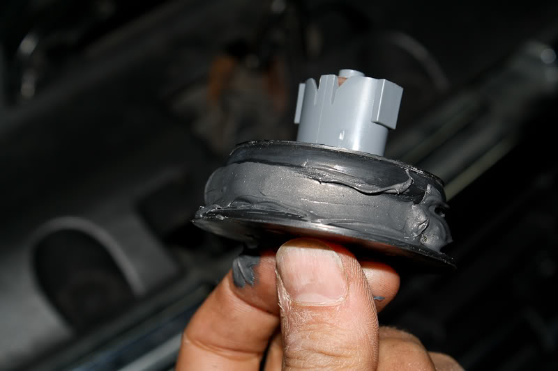
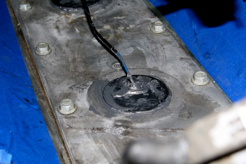
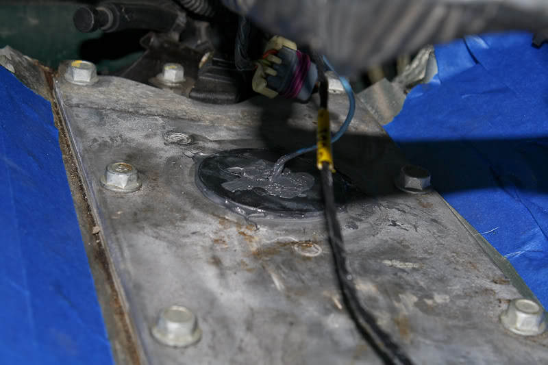
That should keep the water out.
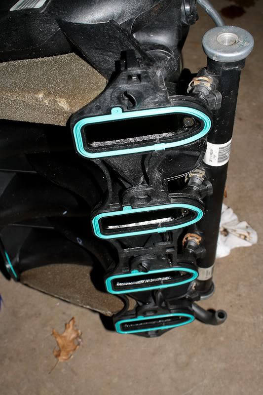
Next, clip the new intake manifold gaskets to the manifold, make sure the surface on the heads is clean, the sub-harness out of the way, and set the manifold back onto the engine.
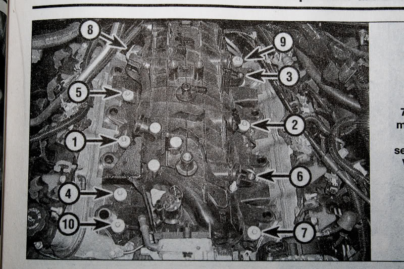
Torque the intake manifold bolts in this order, FIRST to 44 in-lbs (~4 ft-lbs, or as close as you can get), and SECOND to 89 in-lbs (~7.5 ft-lbs).
Put the throttle body back in place, and torque it down. Torque spec on the TB is 106 in-lbs (~9 ft-lbs).
Clip the plug for the knock sensor sub-harness back to the intake manifold, plug it and all the other sensors back in, and put the harness back in place, re-connect the fuel lines, EVAP line, all the brackets, intake tube, and anything else that was removed. Assembly is the exact reverse of disassembly, no real tricks.
Re-connect the battery, and you should be good to go.
I think that's everything, but I'm tired as hell, and may have missed some things. If anyone sees any incorrect info, PLEASE let me know, and I'll fix it.
Remove the black plugs from the valley cover.
You can sort of see that my rear sensor was sitting in about 2" of water.
This is the corrosion on an engine with 25,000 miles:
Unbolt both knock sensors, I believe they take a 22mm deep socket.
This is the most important step. Get your torque wrench, and torque the new knock sensors to EXACTLY 15 ft-lbs. If they are too tight, they will be over-sensitive, and if they are too loose they can cause false knock.
Next, take some RTV, and apply it to the rubber plugs to seal off the holes. This is how I applied it:
That should keep the water out.
Next, clip the new intake manifold gaskets to the manifold, make sure the surface on the heads is clean, the sub-harness out of the way, and set the manifold back onto the engine.
Torque the intake manifold bolts in this order, FIRST to 44 in-lbs (~4 ft-lbs, or as close as you can get), and SECOND to 89 in-lbs (~7.5 ft-lbs).
Put the throttle body back in place, and torque it down. Torque spec on the TB is 106 in-lbs (~9 ft-lbs).
Clip the plug for the knock sensor sub-harness back to the intake manifold, plug it and all the other sensors back in, and put the harness back in place, re-connect the fuel lines, EVAP line, all the brackets, intake tube, and anything else that was removed. Assembly is the exact reverse of disassembly, no real tricks.
Re-connect the battery, and you should be good to go.
I think that's everything, but I'm tired as hell, and may have missed some things. If anyone sees any incorrect info, PLEASE let me know, and I'll fix it.
Dec 7, 2010 | 02:40 PM
#3


cant believe that hunk of junk runs that fast...
but seriously good write up, looks like you need a catch can and hope you cleaned those ports out while you were there..
but seriously good write up, looks like you need a catch can and hope you cleaned those ports out while you were there..
Last edited by skolman91; Dec 7, 2010 at 02:53 PM.
Dec 7, 2010 | 02:56 PM
#4
Dec 7, 2010 | 05:53 PM
#5
Thread Starter
Joined: Nov 2009
Posts: 1,102
Likes: 1
From: Central NJ
A catch can is in the plans, and I was on too tight of a schedule to clean everything up the way I would have liked to (it was getting late into the night, and I needed the truck drivable the next day for work).
Dec 7, 2010 | 06:02 PM
#6
Where did you read about needing to remove the bolts in a certain manner? My AllData doesn't mention that. I have always followed that bolt tightening sequence though with my inch-lbs torque wrench. I really don't think it makes a difference though.
here's how I did mine, and I also replaced the wiring harness to the sensors themselves as I've read this can cause the SES problems as well.

here's how I did mine, and I also replaced the wiring harness to the sensors themselves as I've read this can cause the SES problems as well.
Dec 7, 2010 | 07:36 PM
#7
Thread Starter
Joined: Nov 2009
Posts: 1,102
Likes: 1
From: Central NJ
Where did you read about needing to remove the bolts in a certain manner? My AllData doesn't mention that. I have always followed that bolt tightening sequence though with my inch-lbs torque wrench. I really don't think it makes a difference though.
here's how I did mine, and I also replaced the wiring harness to the sensors themselves as I've read this can cause the SES problems as well.
[img]https://img340.imageshack.us/img340/3424/cimg1611.jpg[img]
here's how I did mine, and I also replaced the wiring harness to the sensors themselves as I've read this can cause the SES problems as well.
[img]https://img340.imageshack.us/img340/3424/cimg1611.jpg[img]
Trending Topics

 Think ima make dis a sticky
  Dec 7, 2010 | 09:22 PM
#9
Thread Starter
Joined: Nov 2009
Posts: 1,102
Likes: 1
From: Central NJ
Dec 7, 2010 | 09:32 PM
#10
 My truck's a tidbit too filthy for pics at the moment, but I haven't put the winter wheels on it yet...so it's not out of the question...maybe some snow shots!