
LS6 Intake Swap
 Feb 26, 2006 | 11:50 AM
#1

Thread Starter
TECH Fanatic
iTrader: (3)
Joined: Oct 2003
Posts: 1,612
Likes: 0
From: Winston Salem NC
LS6 intake swap
Heres a brief write-up on what all I�ve encountered during my swap to the LS6 intake
Hopefully this will help others that would like to do this swap
There are a few ways you can go about this so it�s kind of hard to make a step by step
type write-up
So I'll just stick to sharing my experience
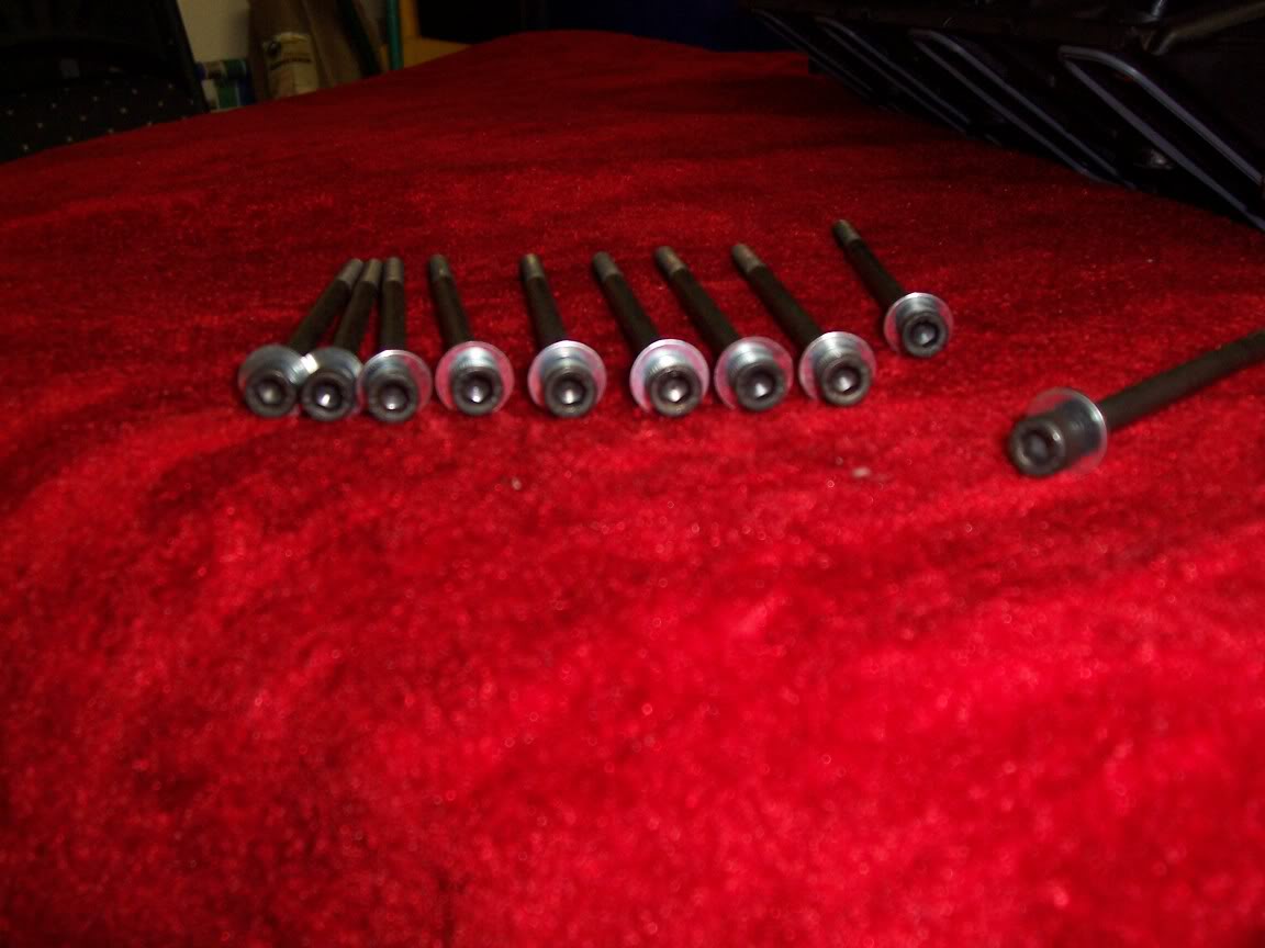
Intake
You will need longer bolts or car bolts M6X100
110mm long
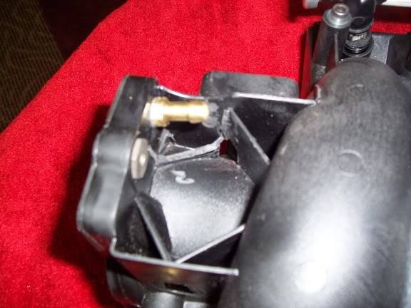
The ls6 intake doesn�t have a nip that goes to the valve cover vent on the pass side
I cut away as shown below, drilled and tapped with a 1/8 npt tap for a brass fitting
(This was drilled at a slight angle)
You may be able to tap a fitting into the intake tube �not sure though�
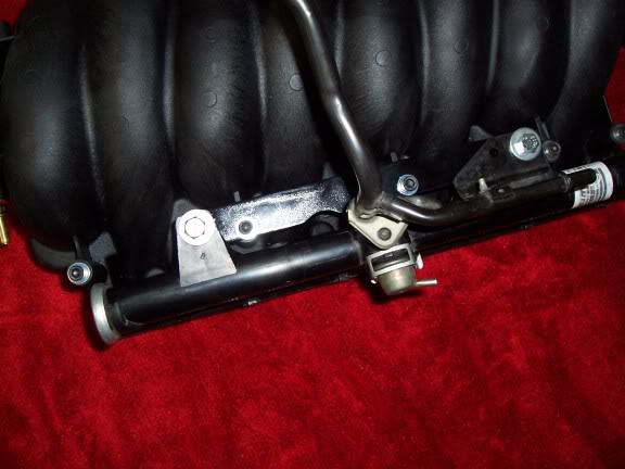
Fuel rails and injectors
I made a bracket for the fuel rails
I used 1/8 X 1� steel stock, cut out for the injector bosses,
Spacers welded on, drilled and tapped the spacers, drilled for the intake bolts
and its good to go
Injectors�
Facts
1 The truck injectors will not fit inside the injector bungs on the intake
2 The seal kit (o rings) part number between the car and truck injector is different
Heres why they don�t fit
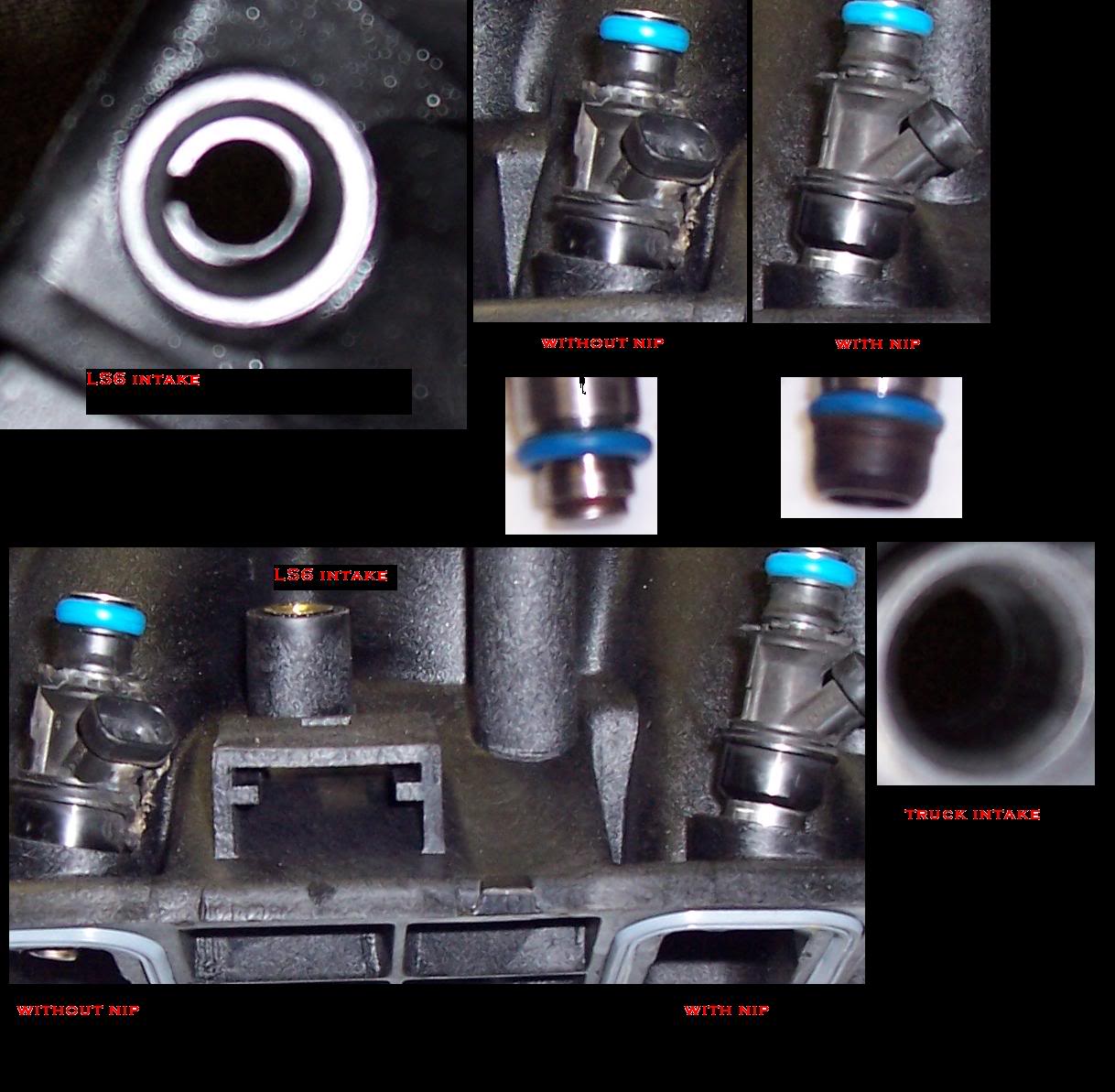
I removed the plastic tips on the injectors to clear the C shape at the bottom of the injector bung and replaced the lower Orings with the ones from an F body
Water pump
There are basically 3 different style water pumps out there
The trucks' /press on pulley
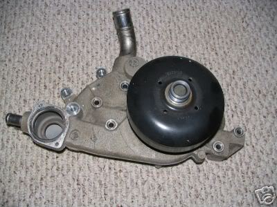
The cars'/ press on pulley
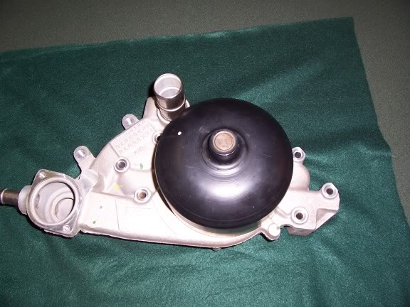
And the 97 corvette, which has the bolt on pulley
Since the outlet on the truck WP is up high the TB will hit the upper outlet
(especially drive by wire TBs)
I believe the cable driven TBs can get away with just cutting down the upper outlet
"not sure though"
Mine is DBW
so I used the 97 vette WP
I got it from NAPA reman "part number 58-544"
And ordered a pulley from GM
This moves the outlet location to the lower boss, which will clear the TB
What�s the significance in the bolt on pulley?
Simple, the difference in the truck and car accessories is different
The car accessories push the belt alignment back towards the engine.
The 97 vette WP will have to be spaced out approx. 3/4 to keep belt alignment in check.
The bolt on pulley allows spacing pretty easily
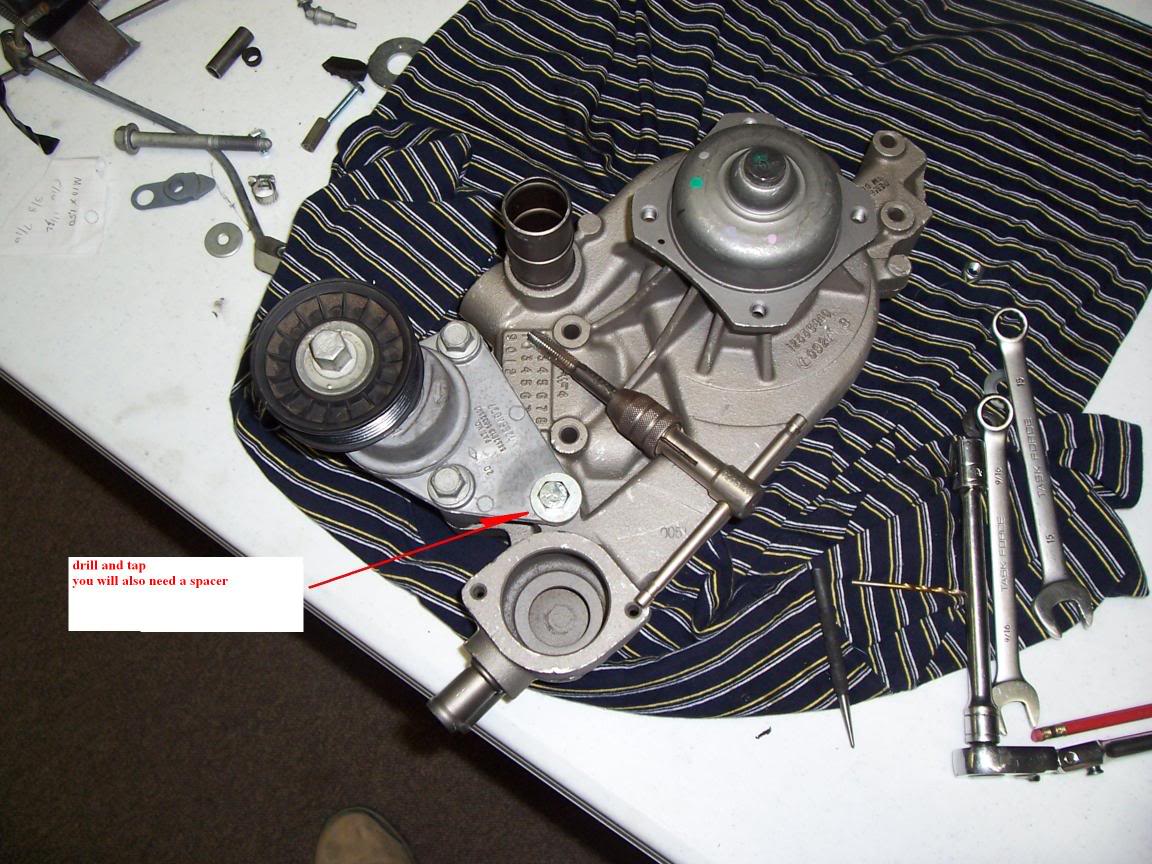
But still, there�s another issue,
The tensioner bracket
The vette water pump has a boss there for the 3rd bolt but its not tapped
That�s a simple fix though
Drill it, tap It, put a spacer between the tensioner and WP, and you�re done
Use caution though
You don�t want to bust through into the WP
Heres a brief write-up on what all I�ve encountered during my swap to the LS6 intake
Hopefully this will help others that would like to do this swap
There are a few ways you can go about this so it�s kind of hard to make a step by step
type write-up
So I'll just stick to sharing my experience
Intake
You will need longer bolts or car bolts M6X100
110mm long
The ls6 intake doesn�t have a nip that goes to the valve cover vent on the pass side
I cut away as shown below, drilled and tapped with a 1/8 npt tap for a brass fitting
(This was drilled at a slight angle)
You may be able to tap a fitting into the intake tube �not sure though�
Fuel rails and injectors
I made a bracket for the fuel rails
I used 1/8 X 1� steel stock, cut out for the injector bosses,
Spacers welded on, drilled and tapped the spacers, drilled for the intake bolts
and its good to go
Injectors�
Facts
1 The truck injectors will not fit inside the injector bungs on the intake
2 The seal kit (o rings) part number between the car and truck injector is different
Heres why they don�t fit
I removed the plastic tips on the injectors to clear the C shape at the bottom of the injector bung and replaced the lower Orings with the ones from an F body
Water pump
There are basically 3 different style water pumps out there
The trucks' /press on pulley
The cars'/ press on pulley
And the 97 corvette, which has the bolt on pulley
Since the outlet on the truck WP is up high the TB will hit the upper outlet
(especially drive by wire TBs)
I believe the cable driven TBs can get away with just cutting down the upper outlet
"not sure though"
Mine is DBW
so I used the 97 vette WP
I got it from NAPA reman "part number 58-544"
And ordered a pulley from GM
This moves the outlet location to the lower boss, which will clear the TB
What�s the significance in the bolt on pulley?
Simple, the difference in the truck and car accessories is different
The car accessories push the belt alignment back towards the engine.
The 97 vette WP will have to be spaced out approx. 3/4 to keep belt alignment in check.
The bolt on pulley allows spacing pretty easily
But still, there�s another issue,
The tensioner bracket
The vette water pump has a boss there for the 3rd bolt but its not tapped
That�s a simple fix though
Drill it, tap It, put a spacer between the tensioner and WP, and you�re done
Use caution though
You don�t want to bust through into the WP
Feb 26, 2006 | 11:50 AM
#2
Thread Starter
TECH Fanatic
iTrader: (3)
Joined: Oct 2003
Posts: 1,612
Likes: 0
From: Winston Salem NC
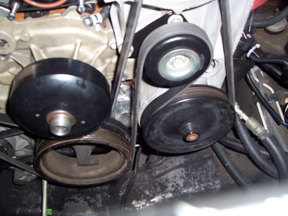
Idler pulley
The stock location of the idler pulley will not clear the TB
The pulley will need to be removed, relocated and the stock boss cut off for TB clearance
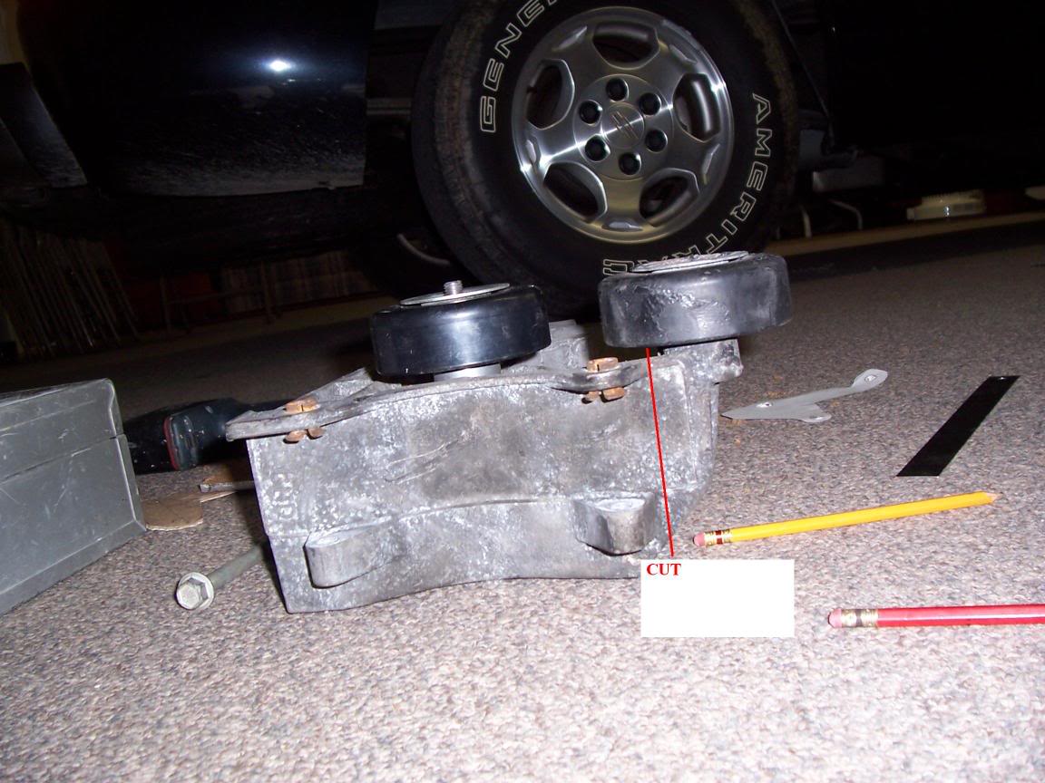
this is how mine looked after cutting
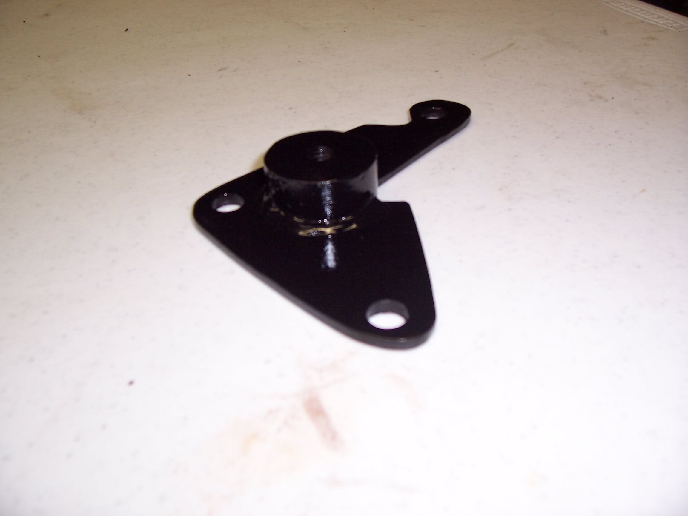
I originally bought the speartech bracket but it didn�t work with the 97 vette WP
And belt routing
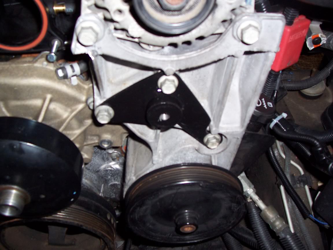
I made my own bracket to place the idler lower and more to the right
This lets me run the belt under the WP and clear the water pump outlet
Heres what I made
The speartech bracket will work fine if you have the equipment to modify the
WP like they do
This requires, to the best of my knowledge,
Cutting and welding the upper outlet tube to make it a 90*
And machining the water pump boss so it can be pressed in
Or�drilling and welding it in
I didn�t have the tools to machine the water pump and don�t like the idea of welding on the WP
Thats why I chose the 97 vette WP and making my own bracket
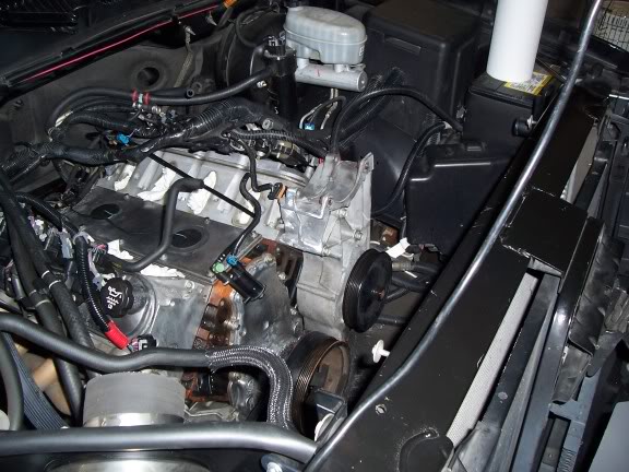
Heres what the belt routing will look like
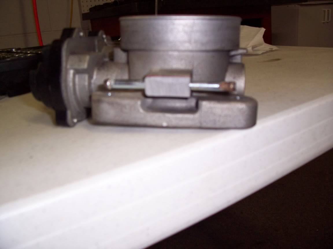
Throttle body
There was one more clearance issue with the TB and WP
The bottom of the TB needs to be shaved a tiny bit to clear the WP housing
This can easily be done with a file or grinder
(This should be true with all truck TBs but I�m not certain)
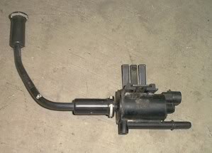
EVAP
There is no place to connect the truck EVAP canister to the intake the way it�s connected
To the truck manifold
I first removed the Oring on the outlet then I took the connector off the PCV hard line and clamped it to the outlet of the Canister
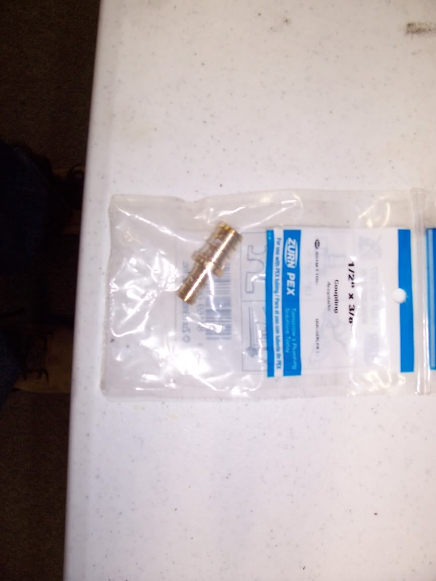
I then used a reducer � by 3/8
And connected it all together with a 5/16 fuel line to the brass nip on the driver side of the intake
PCV
For this I just ran a 3/8" transmission cooler line from the hard line to the pass side of the intake
Heres a pic of the vac lines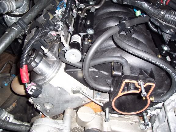
FPR
(Fuel pressure regulator, if equipped)
I used a vacume line attached to existing line with rtv
Back to the small nip at the very back of the intake
I do not have results yet, but will soon
What really made me do this swap
is the theories I've had based on the results
and powerband with my application
as well as the design of the truck intake itself.
It really came to the light when I compared Mattrem's dyno graph with mine
A 228/230 should pull higher than a 216/220
with everything else being basically the same.
I've also noticed this restriction in several other graphs I've seen
It appears that 5000 and 350hp is the magic numbers where the intake begins to run out of breath
I would also like to give Sportside a big thanks for getting my mind in the right direction with all of our back and forth PMs about reverse split cams, intake restrictions and so on
After presenting the results and theories to Richard@wcch , he seems to agree and is interested in seeing the results
Only one way to know for sure though, I should have track times and dyno graphs
to compare the 2 soon
I'll post results reguardless if its good or bad
The stock location of the idler pulley will not clear the TB
The pulley will need to be removed, relocated and the stock boss cut off for TB clearance
this is how mine looked after cutting
I originally bought the speartech bracket but it didn�t work with the 97 vette WP
And belt routing
I made my own bracket to place the idler lower and more to the right
This lets me run the belt under the WP and clear the water pump outlet
Heres what I made
The speartech bracket will work fine if you have the equipment to modify the
WP like they do
This requires, to the best of my knowledge,
Cutting and welding the upper outlet tube to make it a 90*
And machining the water pump boss so it can be pressed in
Or�drilling and welding it in
I didn�t have the tools to machine the water pump and don�t like the idea of welding on the WP
Thats why I chose the 97 vette WP and making my own bracket
Heres what the belt routing will look like
Throttle body
There was one more clearance issue with the TB and WP
The bottom of the TB needs to be shaved a tiny bit to clear the WP housing
This can easily be done with a file or grinder
(This should be true with all truck TBs but I�m not certain)
EVAP
There is no place to connect the truck EVAP canister to the intake the way it�s connected
To the truck manifold
I first removed the Oring on the outlet then I took the connector off the PCV hard line and clamped it to the outlet of the Canister
I then used a reducer � by 3/8
And connected it all together with a 5/16 fuel line to the brass nip on the driver side of the intake
PCV
For this I just ran a 3/8" transmission cooler line from the hard line to the pass side of the intake
Heres a pic of the vac lines
FPR
(Fuel pressure regulator, if equipped)
I used a vacume line attached to existing line with rtv
Back to the small nip at the very back of the intake
I do not have results yet, but will soon
What really made me do this swap
is the theories I've had based on the results
and powerband with my application
as well as the design of the truck intake itself.
It really came to the light when I compared Mattrem's dyno graph with mine
A 228/230 should pull higher than a 216/220
with everything else being basically the same.
I've also noticed this restriction in several other graphs I've seen
It appears that 5000 and 350hp is the magic numbers where the intake begins to run out of breath
I would also like to give Sportside a big thanks for getting my mind in the right direction with all of our back and forth PMs about reverse split cams, intake restrictions and so on
After presenting the results and theories to Richard@wcch , he seems to agree and is interested in seeing the results
Only one way to know for sure though, I should have track times and dyno graphs
to compare the 2 soon
I'll post results reguardless if its good or bad
 Feb 26, 2006 | 12:36 PM
#4

TECH Addict
Joined: Feb 2003
Posts: 2,864
Likes: 1
From: Geneseo, NY
Interesting....and WAAAAAAY different from what I went through to put an LS1 intake on mine:
* My injectors dropped right in....with the exception of the height difference. my LS1 intake was a '98 though so later LS6's might be different
* Manifold bolts were the same for both
* MY LS1 intake had the PCV nipple already installed from the factory
* TB cleared the WP housing without grinding
* Cutting down the truck WP outlet to 3/4" tall and putting an elbow in worked for me
Nice write-up though....VERY informative
Feb 26, 2006 | 01:27 PM
#6
Thread Starter
TECH Fanatic
iTrader: (3)
Joined: Oct 2003
Posts: 1,612
Likes: 0
From: Winston Salem NC
Originally Posted by Yelo
Interesting....and WAAAAAAY different from what I went through to put an LS1 intake on mine:
* My injectors dropped right in....with the exception of the height difference. my LS1 intake was a '98 though so later LS6's might be different
* Manifold bolts were the same for both
* MY LS1 intake had the PCV nipple already installed from the factory
* TB cleared the WP housing without grinding
* Cutting down the truck WP outlet to 3/4" tall and putting an elbow in worked for me
Nice write-up though....VERY informative
* My injectors dropped right in....with the exception of the height difference. my LS1 intake was a '98 though so later LS6's might be different
* Manifold bolts were the same for both
* MY LS1 intake had the PCV nipple already installed from the factory
* TB cleared the WP housing without grinding
* Cutting down the truck WP outlet to 3/4" tall and putting an elbow in worked for me
Nice write-up though....VERY informative
thanks for chiming in
I take yours is cable driven from your previous posts
and what you've told me through PMs
Thats why I included that part about the cable driven TBs
but unfortunately this doesnt work with the DBW's
Thats crazy that its that much difference between the ls1 and ls6,
especially the bolts

The fitting I threaded in goes to the pass. side valve cover vent
From the best I can tell,
The car had this on the TB where the trucks' is attached to the intake
Feb 26, 2006 | 01:39 PM
#7
Thread Starter
TECH Fanatic
iTrader: (3)
Joined: Oct 2003
Posts: 1,612
Likes: 0
From: Winston Salem NC
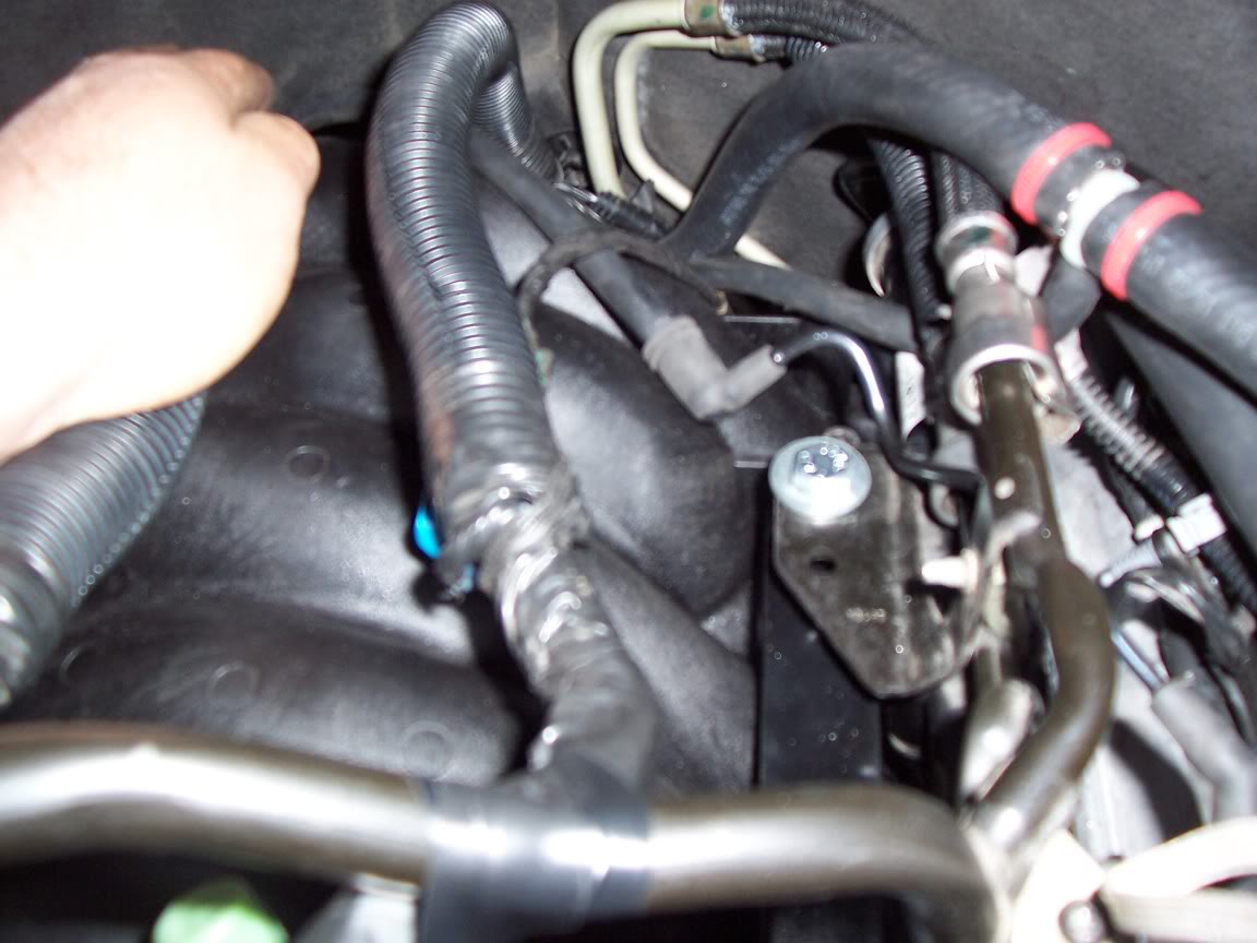
Originally Posted by BenKey
Good write-up. Getting ready to do a FAST intake myself. Can you take a better pic of what you do with the EVAP cannister? It's blocked in the pic.
was take the connector off the hard line from the PCV
clamped it to the stub that had the oring on it
then reduced it with
and let it feed into the brass nip on the front and driver side of the intake
Ill try to get a better pic of it
I may be going with a fbod type canister soon to clean things up a bit
here it is
Trending Topics
 Feb 26, 2006 | 07:07 PM
#9

Great post Kano!
Everything looks real nice too. I like your belt routing better than the speartech way. Are you using a stock length belt? Do you have any sketches for the idler bracket and fuel rail adapters? Also what did you do with that massive wire loom that goes over the top of the truck intake?
Can't wait for the results.
Feb 26, 2006 | 07:21 PM
#10
Thread Starter
TECH Fanatic
iTrader: (3)
Joined: Oct 2003
Posts: 1,612
Likes: 0
From: Winston Salem NC
Originally Posted by 02sierraz71_5.3
Glad to see you got everything fabed up and on the truck, count me in for dyno/track day.
I hope I can make my first run at nam
here pretty soon
still waiting on the WP spacer ring and pulley
to get back
Im going to order another pulley and stock make my own spacers
tomorrow
Its been over 2 weeks now and Im tired of waiting
Ill let ya know when she 's ready to roll