Transgo HD2: dual fed direct drum?
 08-26-2012, 07:04 AM
#1
After all my recent transmission BS, I picked up a new unmolested transmission from a junkyard. There were a few stripped bolt holes in the old transmission and the valve body bolt holes weren't in good shape either, and I'm sure the case lugs were a bit worn too from all the snap ring confusion last year. So I turned that crusty bitch in and got a different one. Anyway...I got the HD2 kit from summit and have been checking it out...
It says right on the front page: "Dual feed direct clutch: Triples 3rd gear holding power". I have been tearing through fluid diagrams for like 3 hours now and I don't see how the outer portion of the piston gets fluid when 3rd gear is applied. The OLD Transgo HD2 kit accomplishes this by removing the 3rd/reverse check ball and re-routing fluid in a custom circuit outside the valve body to maintain reverse gear. The new kit doesn't even mention the 3rd/reverse check ball, and since thats the circuit that supplies fluid to the outside portion of the direct piston I don't see how it is dual fed at all.
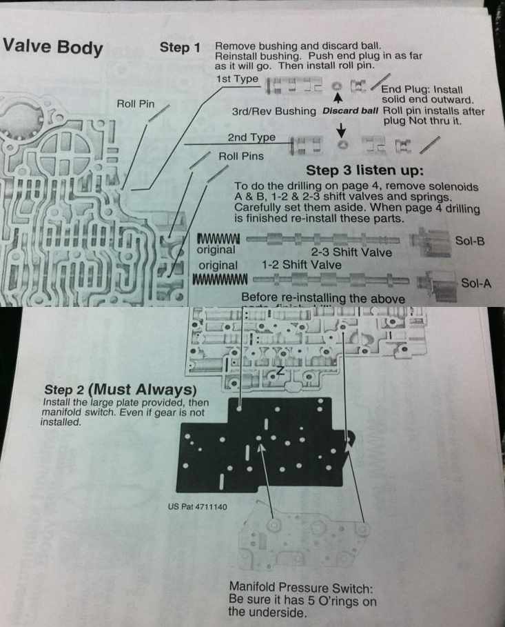
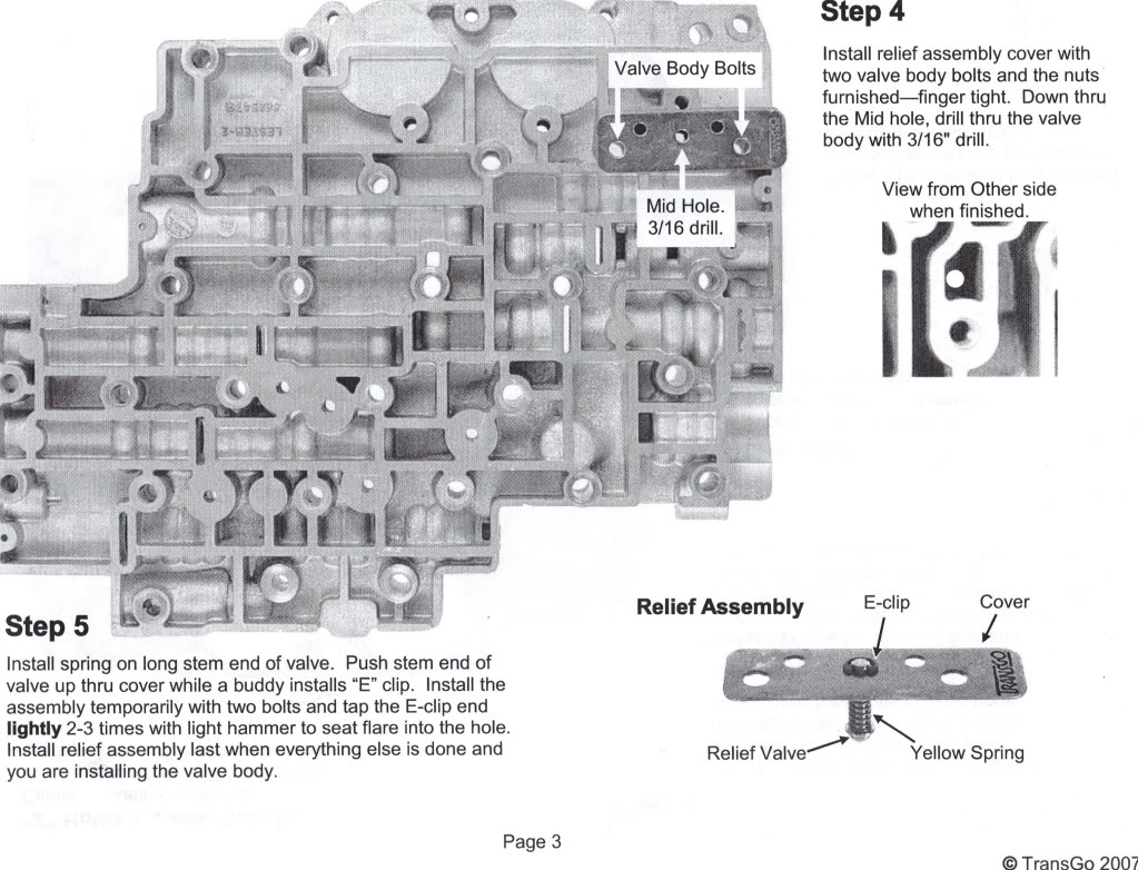
These are the instructions from the old style HD2 kit, specifically the part that says to remove the 3rd/reverse check ball. Both kits instruct you to remove the small check ball, but only the old one removes the big ball. In the lower part of the picture, you can see the additional plate Transgo provides to re-route the reverse circuit so you don't lose reverse by pulling the large check ball.
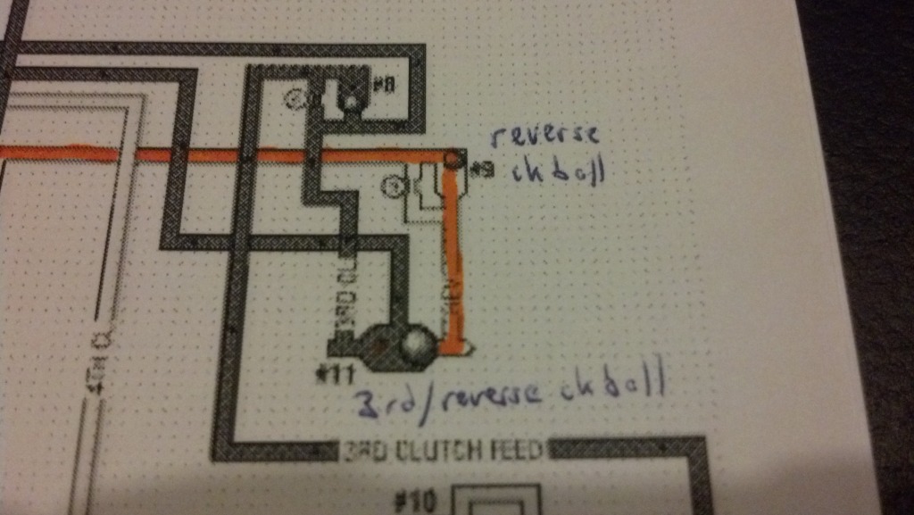
This is how fluid is routed on the fluid diagram... The reverse circuit in orange is not applied, so the larger outer portion of the piston does not receive any fluid at all in 3rd. In reverse the check ball moves and the fluid applies to the whole piston.
Are they full of **** or am I missing something here?? I don't want to put this thing in without dual feeding 3rd gear, especially not after hearing all the stories about burning the direct clutches under high load. Can any trans guys shed some light on this?
It says right on the front page: "Dual feed direct clutch: Triples 3rd gear holding power". I have been tearing through fluid diagrams for like 3 hours now and I don't see how the outer portion of the piston gets fluid when 3rd gear is applied. The OLD Transgo HD2 kit accomplishes this by removing the 3rd/reverse check ball and re-routing fluid in a custom circuit outside the valve body to maintain reverse gear. The new kit doesn't even mention the 3rd/reverse check ball, and since thats the circuit that supplies fluid to the outside portion of the direct piston I don't see how it is dual fed at all.
These are the instructions from the old style HD2 kit, specifically the part that says to remove the 3rd/reverse check ball. Both kits instruct you to remove the small check ball, but only the old one removes the big ball. In the lower part of the picture, you can see the additional plate Transgo provides to re-route the reverse circuit so you don't lose reverse by pulling the large check ball.
This is how fluid is routed on the fluid diagram... The reverse circuit in orange is not applied, so the larger outer portion of the piston does not receive any fluid at all in 3rd. In reverse the check ball moves and the fluid applies to the whole piston.
Are they full of **** or am I missing something here?? I don't want to put this thing in without dual feeding 3rd gear, especially not after hearing all the stories about burning the direct clutches under high load. Can any trans guys shed some light on this?
 08-26-2012, 10:05 AM
#2

You should now have a stacked plate that is how they are redirecting the oil for the dual feed. The idea now is to use the entire piston surface instead of just part of it. Also IIRC you were also drilling four .125 holes in the valve body casting with the old kit. I have always taken it one step further with leaving the second ring off the center support and also the inner lip seal in the drum. In reality that is all you really need to do.
08-26-2012, 12:41 PM
#3
You took it a step further leaving off those drum and center support seals in the old kit or the new kit? I saw the oil path in the triple plate, but it looked like a pressure leak so i figured i was missing something. Does the 3rd/rev circuit connected to the reverse circuit not apply the low/reverse band? In the old kit they plug that hole in the separator plate to prevent that pressure leak...
08-26-2012, 04:33 PM
#4

This is what i did when i rebuilt my 4L80e... Vince helped me ALOT, thanks again buddy! I used all the springs from the HD2 kit and that was about it...
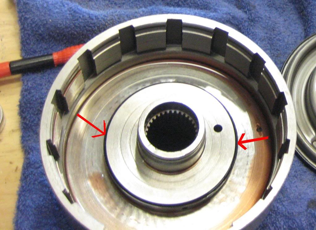
Leave off this gasket on the center support
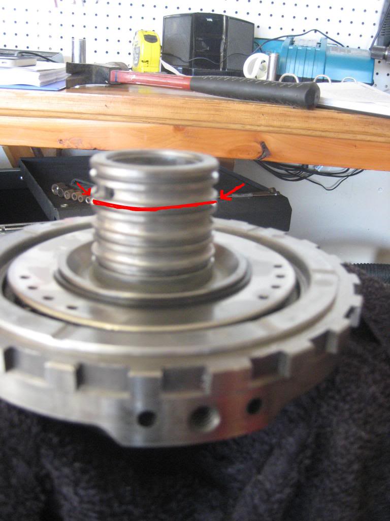
I took it a step further and filed down the ridges where the gasket sat. Since this piece is stationary it does not have to be balanced....
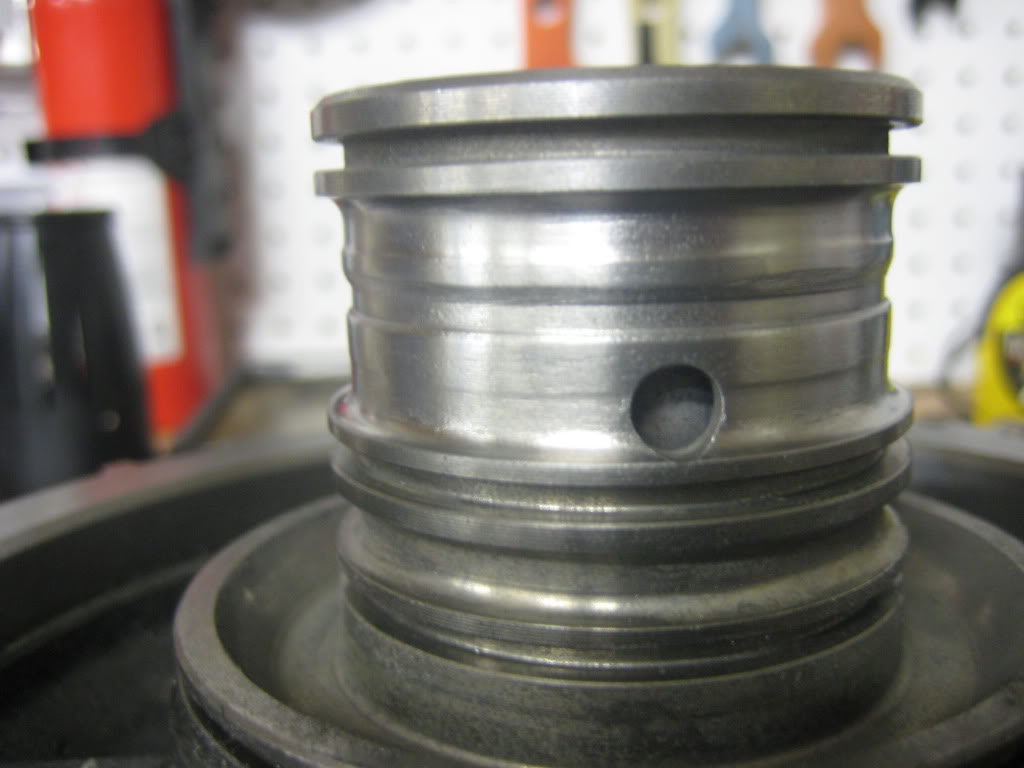
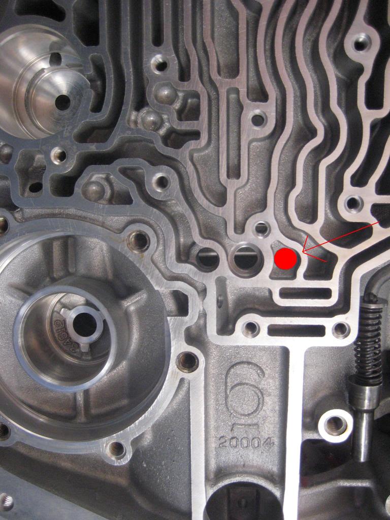
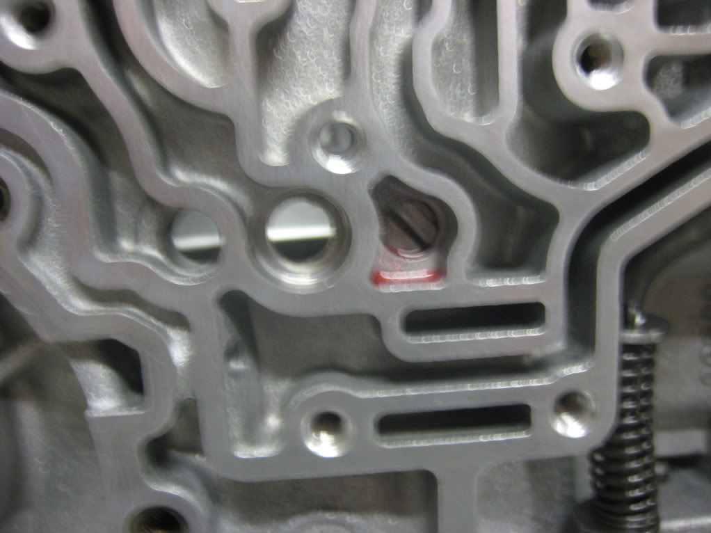
Then you fill in this hole, use red locite on it...
lastly remove this gaskets and your done...
So do those 3 things and your will dual feed the direct drum... Leave the Transgo spacer plate in the box... also don't do steps 4 and 5 in the instructions.
Instead buy a self-regulating Boost valve from Sonnax.
4L80E transmission boost valve kit Sonnax 34200-10K
Leave off this gasket on the center support
I took it a step further and filed down the ridges where the gasket sat. Since this piece is stationary it does not have to be balanced....
Then you fill in this hole, use red locite on it...
lastly remove this gaskets and your done...
So do those 3 things and your will dual feed the direct drum... Leave the Transgo spacer plate in the box... also don't do steps 4 and 5 in the instructions.
Instead buy a self-regulating Boost valve from Sonnax.
4L80E transmission boost valve kit Sonnax 34200-10K
08-26-2012, 04:52 PM
#7
That is what I was wondering though, Corey. Thanks for the post. I wanted to know if there was a way to use the internal dual feed method with the transgo kit...seems like the best of both to me.
As usual, Vince is always a huge help. Question for you before I continue, Vince... I have the valve body that Jake's Performance sent me for my other 2006 trans. It doesn't have steps 4 and 5 from the Transgo instructions drilled into it Can I use that valve body? Are there any differences other than the different style EPC? I'd love to be able to use the brand new VB on this trans.
As usual, Vince is always a huge help. Question for you before I continue, Vince... I have the valve body that Jake's Performance sent me for my other 2006 trans. It doesn't have steps 4 and 5 from the Transgo instructions drilled into it
Trending Topics
08-26-2012, 04:55 PM
#8
Honestly i don't know if you can use that VB... I wonder what other mods they might have done to it... Definitely get a stock spacer plate and drill it... Perhaps disassemble both VBs side by side to see what differences there are, otherwise try to pick a new VB or just rock that one you drilled. Vince mentioned to me that steps 4&5, he had issues on the dyno with alot of power, it would hang and not relieve the pressure like it should...
08-26-2012, 04:58 PM
#9
Yeah I don't want ANY issues anymore. I am done pulling transmissions... The valve bodies look similar enough, but I won't go ahead with it until I have the word from the master lol. I can use the stock plate that was on the trans when I got it. Assuming its all kosher together.
08-26-2012, 05:02 PM
#10
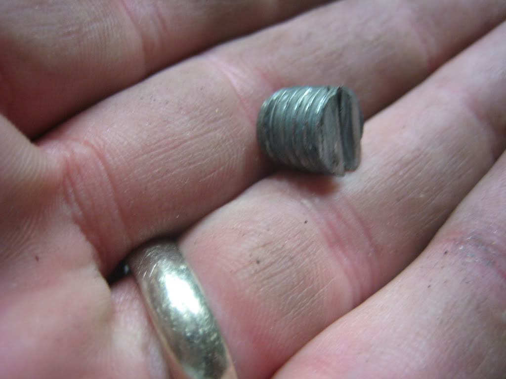
i reused my stock plate. Just make sure it is not dented from the *****... I went with Torlon Check *****
700R4 Check Ball Torlon for 700/700-r4/th700 transmission
700R4 Check Ball Torlon for 700/700-r4/th700 transmission