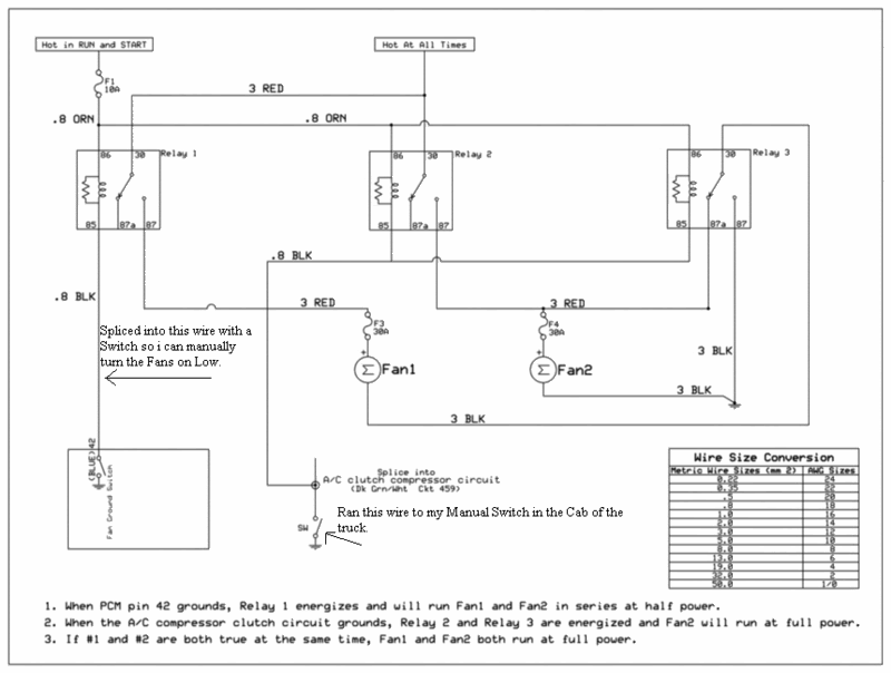
Efan harness 101
#1
TECH Senior Member
Thread Starter
iTrader: (10)
Join Date: Oct 2004
Location: Crystal Springs, MS
Posts: 14,068
Likes: 0
Received 2 Likes
on
2 Posts
I did this from my phone so somebody please proof read it. Then we can make it official.
Efan wiring 101
How to make your own efan harness pick one of the two ways.
Example #1
You need two 40 amp relays that have atleast 4 pins. You can use 5 pin relays if need be.
12 or 10ga wire for the power and ground
18ga wire for the trigger
Either 1/4" spade connectors or relay sockets
Ive used crimp on spades but i perfer to solder the wire to the connector just for the heck of it. And heat shrink it.
Use 12 or 10ga wire on pins 30, 87, and 87A.
Use 18ga on pins 85 and 86.
This is how i wired the LS1 fans on my buddys 1980 4x4 with a LS 408ci and the factory 1980 radiator. Fan 2 very rarely comes on unless he is running it hard in 4 Low.
If you go by this, you can add another wire in all the Pin 85's and run it in the cab, hook to a switch. Ground the other leg of the switch and you have a manual override to turn the fans on.
This will only tell you when the PCM or manual override is commanding the fans on:
You can also wire in a LED on this wire. Put 12V+ on the hot side of the LED and connect the ground wire to the wire off PIN 85. When the PCM or your manual override switch is activated you can see by your indicator.
This way lets you know that all your fuses and relays are In working order.
Wire in LED where the positive side is connected to Relay #1 PIN 87. Ground the other side. This lets you know the relay has power and is sending it to Fan #1.
For Fan #2 hook the positive side of LED to either Relay #2 pin 87 or Relay #3 pin 87A. Ground the other wire of LED.
Relay #1
30 12 volt + with atleast a 30A fuse
87 positive side of Efan #1
85 PCM pin 33
86 12 volt + *(ive soldered in a 18ga wire into the connector of pin 30, saves a lil wire and a fuse, to power the trigger. Instead of running another wire all the way to your power source. I did this on all the relays. Do as you like. )
Relay #2
30 12 volt + with atleast a 30A fuse
87 positive side of Efan #2
85 PCM pin 42
86 12 volt +
This is how i have the 2005 34" Efans wired on my 2000 Silverado.
Relay #1
30 12 volt + with a 40A fuse
87 positive side of Efan #1
85 PCM pin 42
86 12 volt +
Relay #2
30 12 volt + with atleast a 30A fuse
87 positive side of Efan #2
85 PCM pin 33
86 12 volt +
Here is where you need the 5 pin relay
Relay #3
30 Run Fan #1 ground to here, dont ground it anywhere else
87 Ground to frame, block, or battery. Any good ground.
87A Fan #2 positive side
85 Splice into the PCM Pin 33 wire. Or you can run a wire from Relay #2 pin 85
86 12 volt +
Now get to work!!
I used a 6 circuit fuse block mounted to the rear of the factory fuse box that i ran a #6 wire from the red power box on the driver side for power and a #6 wire for the ground strip on the fuse block to the engine block.
That way the fuses are easy to get to and gives you plenty of space for other accessories that need a fuse or a good ground.
When i get some more time where i can think ill try and do a writeup on how to troubleshoot a EFan harness problem.
Last edited by nonnieselman; 07-12-2012 at 01:14 PM.
#4
Mod with training wheels
iTrader: (16)
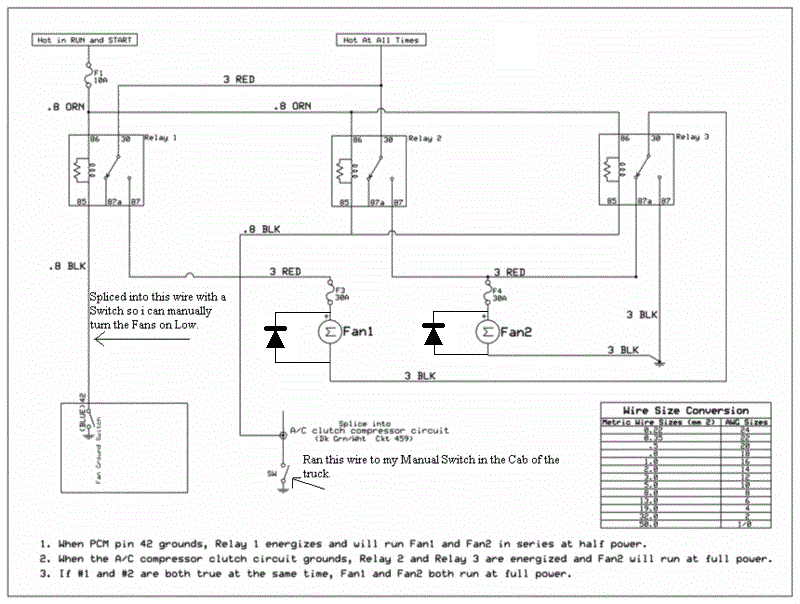
Looks almost identical to the one I made
http://i271.photobucket.com/albums/j...s/IMG_1548.jpg
I added a diode to each fan power supply though. Its common practice to shunt inductor current back into itself on a motor circuit after power is shut off, otherwise you have stray potential on your wires.
http://i271.photobucket.com/albums/j...s/IMG_1548.jpg
I added a diode to each fan power supply though. Its common practice to shunt inductor current back into itself on a motor circuit after power is shut off, otherwise you have stray potential on your wires.
#5
TECH Senior Member
Thread Starter
iTrader: (10)
Join Date: Oct 2004
Location: Crystal Springs, MS
Posts: 14,068
Likes: 0
Received 2 Likes
on
2 Posts
Looks almost identical to the one I made
http://i271.photobucket.com/albums/j...s/IMG_1548.jpg
I added a diode to each fan power supply though. Its common practice to shunt inductor current back into itself on a motor circuit after power is shut off, otherwise you have stray potential on your wires.
http://i271.photobucket.com/albums/j...s/IMG_1548.jpg
I added a diode to each fan power supply though. Its common practice to shunt inductor current back into itself on a motor circuit after power is shut off, otherwise you have stray potential on your wires.


