GMT900 408/80e conversion
 01-01-2010, 03:48 PM
#11
TECH Apprentice
Thread Starter
iTrader: (9)

Join Date: Mar 2004
Location: Denton, Texas
Posts: 343
Likes: 0
Received 0 Likes
on
0 Posts
Swapping the reluctor wheel is easy if you have the alignment tool. It costs $200+ for the tool from Goodson. I had my machine shop do it for me, cost $50 to install since he had to build a tool to align it. He put it in the oven for an hour at 450 degrees and just slid it on and aligned it.
2" lowering shackles went on the rear of the GMT900 and I took the rear riser blocks out from between the axle and springs. The truck sits almost level, now. Not sure if I am going to lower it much more, its very stealthy like this and since I don't do any canyon carving I'm not so sure I really need it low. I might go a couple inches lower all around but that's about it.
Pics are located in the "My Garage" section on the other site.


 01-01-2010, 07:48 PM
#14
TECH Apprentice
Thread Starter
iTrader: (9)
Join Date: Mar 2004
Location: Denton, Texas
Posts: 343
Likes: 0
Received 0 Likes
on
0 Posts
Started working on completing the engine assy today but hit a wall, the cam retainer plate has a silicone seal molded on the engine block side of the retainer plate and there was a small nick in the silicone. That will cause a leak and loss of oil pressure so I moved on to other parts of the assembly for now. I'll pick up a new cam retainer plate tomorrow at the dealership if they have one in stock. I put the lifters and retainers in, a little loctite on the bolts holding the retainers in place torquing them to 90 in/lbs and then bolted the heads down using ARP head studs torqued at 85 ft/lbs on the large bolts and 25 ft/lbs per the new ARP specs. This engine block is a newer model that has all 10 studs/bolts the same length.
Since the engine is the older Gen3 style engine I had to put the Gen3 valley cover on, installed the knock sensors just for a filler(not doing anything with them anyway) and installed the knock sensor harness. I figured this would be needed so that water does not pool in the knock sensor pockets in the valley pan. You sure wouldn't want moisture getting into the oil via the valley cover. I also used some gorilla tape (black duct tape, super strength) to hold the wiring down and sealing the knock sensors more seriously.
While I was assembling the heads to the block I looked in the intake runners and saw a piece of fiberglass wedged between a valve and the seat. I made a flat bar to compress the spring so I could get the piece out. I wonder where in the world that could have come from? It looked kind of like a fiberglass reed.
Where do you get your torque wrenches recalibrated? Sears wants almost the price of a new wrench to service this one. I put a measured 38 lb weight 1 foot from the ratchet head and kept adjusting the torque wrench until it clicked. It was 10 lbs off. I'm not too surprised considering this wrench is about 15 years old. Maybe I'll just go buy a new one.
Since the engine is the older Gen3 style engine I had to put the Gen3 valley cover on, installed the knock sensors just for a filler(not doing anything with them anyway) and installed the knock sensor harness. I figured this would be needed so that water does not pool in the knock sensor pockets in the valley pan. You sure wouldn't want moisture getting into the oil via the valley cover. I also used some gorilla tape (black duct tape, super strength) to hold the wiring down and sealing the knock sensors more seriously.
While I was assembling the heads to the block I looked in the intake runners and saw a piece of fiberglass wedged between a valve and the seat. I made a flat bar to compress the spring so I could get the piece out. I wonder where in the world that could have come from?
Where do you get your torque wrenches recalibrated? Sears wants almost the price of a new wrench to service this one. I put a measured 38 lb weight 1 foot from the ratchet head and kept adjusting the torque wrench until it clicked. It was 10 lbs off. I'm not too surprised considering this wrench is about 15 years old. Maybe I'll just go buy a new one.
Last edited by Red Heartbeat; 01-01-2010 at 08:23 PM.
 01-01-2010, 09:49 PM
#16
TECH Apprentice
Thread Starter
iTrader: (9)
Join Date: Mar 2004
Location: Denton, Texas
Posts: 343
Likes: 0
Received 0 Likes
on
0 Posts
Pics of the victim after debadging and lowering the rear with 2" shackles and removing the spacer block between the springs and axle...
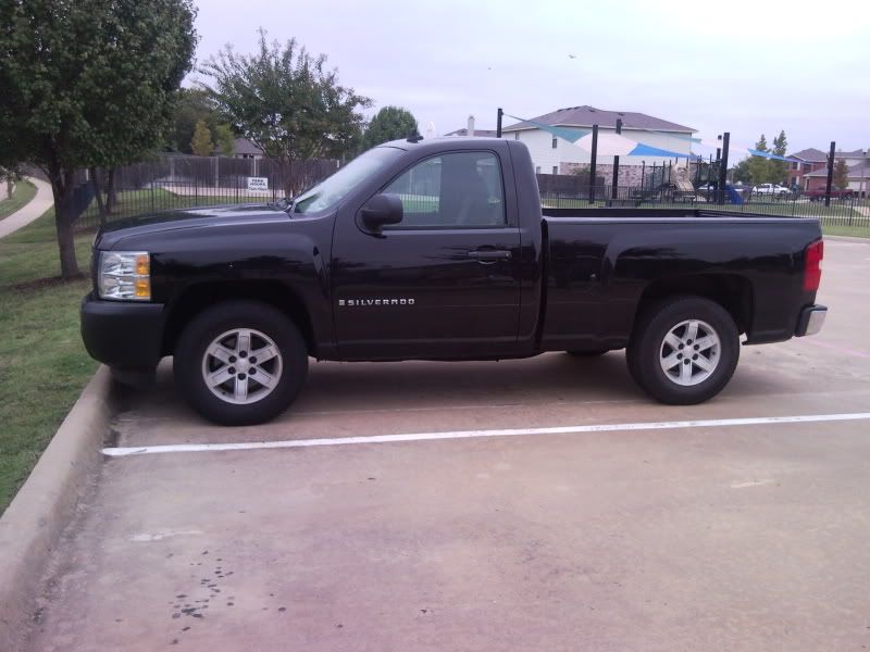
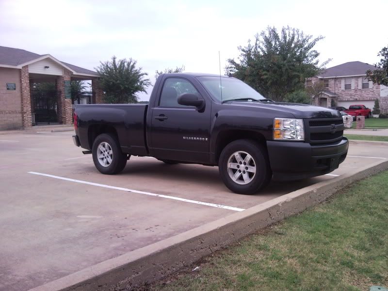
First thing I did when I got it home was remove the rear bowtie and removed the clear off the front bowtie and polished the plastic behind it to get a fully black bowtie for free.
I later shaved the antenna and did the DIC upgrade. And yes, those are GMC wheels on a Chevy. Previous owner did that, looks different than anything else out there.
First thing I did when I got it home was remove the rear bowtie and removed the clear off the front bowtie and polished the plastic behind it to get a fully black bowtie for free.
I later shaved the antenna and did the DIC upgrade. And yes, those are GMC wheels on a Chevy.
Previous owner did that, looks different than anything else out there.
Last edited by Red Heartbeat; 01-01-2010 at 09:55 PM.
 01-02-2010, 02:30 PM
#19
TECH Apprentice
Thread Starter
iTrader: (9)
Join Date: Mar 2004
Location: Denton, Texas
Posts: 343
Likes: 0
Received 0 Likes
on
0 Posts
Picked up cam retainer plate 12589016 at the dealership this morning. The newer cam retainers are a little thinner than the one I had from my 1998 Fbody and it uses countersunk head screws using a torx bit for installation. I've seen guys strip the torx head bolts out trying to remove them so I reused the old bolts with loctite torqued to 18 ft/lbs during the install. Next, the camshaft went in advanced 2 degrees using the new Rollmaster single row timing chain setup. The dowel pin hole in the cam gear was very tight and I had to use the cam bolts to draw the gear onto the dowel. Aligning the timing marks is different on the adjustable setups since you don't have a dot to line up on the crank gear, you use the tooth with the number on it that you setup the advance or retard. My engine has the little plastic timing chain guide that fits between the two gears. To verify I had the alignment correct I used a piston stop screwed into one of the spark plug holes and then rolled the engine forward until it stopped and then scribed a mark on the guide, then rolled it backwards until and stopped and made another mark. Measure the distance between both point and one half of the distance should be damn near TDC. I removed the stop and then moved the pointer to my halfway point and all was good. The cam gear was a tad bit forward, towards the passenger side of the engine so it was advanced just a smidge as I planned. I then removed the bolts and added some loctite and then torqued the bolts to 18 ft/lbs.
Loctite is our friend, it keeps things from loosening at the worst possible times.
Added the oil pump, it is very important to get it centered so that you don't cause a wear spot inside the aluminum housing. I use two indicators, one to locate and center horizontally and one to center it vertically. I leave all bolts loose on the pump and then lightly snug one on each side of the pump. Next, move it all the way up and zero out the indicator then tap it down and check the reading, mine was .011". Do the same thing with the horizontal measurement, measure the slack from left to right. Now lightly tap on the pump until it is located in the middle of the indicated travel in both directions and tighten the two bolts that were just snug. Now remove the other two bolts, put loctite on them and torque to 18 ft/lbs and then do the original two bolts.
Install the windage tray, leaving the two nuts that hold the pickup tube off and torque to 18 ft/lbs. Again, loctite is suggested. Install a new O-ring on the oil pickup tube. Some say to put it in the pump and then slide the tube in, I prefer to put it on the tube and slide it into the pump. Something I started doing lately is putting red silicone sealer in the void area from the installed oring and up to the metal clamp before snugging the pickup tube clamp bolt to 80 in/lbs. The truck tube seems to be forgiving of misalignment due to its floating tube clamp. The Fbody tube has the clamp brazed to the tube and any misalignment can pinch the oring. BMR makes a billet aluminum clamp to help with this issue in the Fbody setup. The red silicone is a kind of 2nd line of defense in case you pinch the seal. Something to check before you do the silicone is checking the clearance of the oil pickup to the bottom of the pan. Install the pickup tube and snug all the bolts down, no seals in place. Put a 3/4" ball of clay/playdoh on the bottom of the pickup tube, wrap some cellophane around it to keep it from sticking to the pan and then put the oil pan gasket down and then put the oil pan on the engine and push to mash the clay. Remove the pan and gasket and then measure the thickness of the clay. I've always shot for 1/2". Shim or bend the tube accordingly. Mine was so far off I had to cut 1/2" out of it and braze it back together, this was due to having to shim the windage tray down for the 4" stroker.
Flushed the pushrod tubes out with solvent and blew the solvent out with compressed air, then dropped the pushrod in place in the engine pushing them down to seat the lifter onto the cam lobe, being sure to lube the ends of the tubes with assembly lube. My engine has Patriot Stage 2 heads and the porting job violated the the intake valve bolt hole. If you don't address this you will have an oil consumption issue. I'm also running those cheap blue Scorpion 1.7 ratio rockers, too. To address the rocker arm bolt hole I take some thread sealing teflon and coated the threads on the intake bolt, only. Wipe the rockers off with a solvent soaked rag and dry with a clean rag. Don't soak your rockers in solvent unless you want to submerge them in oil for a while to get oil back into them. To install the Scorpion rockers I take a factory rocker bolt with one of the 8mm ARP washers on it and slide it into the rocker, turn the rocker upside down and slide a pedestal on it. Assemble one more arm the same way but with the sealant on the other bolt, if you have ported heads, and then assemble the pair together using the C-channel from the Scorpion rocker kit. Take the setup to the head, align the sealant coated bolt with the intake valve and bolt it on torqueing to 22 ft/lbs. Do this 7 more times, fun. LOL I like to do them all with the engine at TDC then turn the engine 1/2 turn and torque them again. I do this a total of four times. It's amazing you get a few that weren't tight the first time around.
I'm about done with all I can do for now until it goes into the truck since I need the covers and oil pan from the 4.8 that's in it now. Hopefully the weather holds up next weekend so that I can put this thing in!
Last edited by Red Heartbeat; 01-02-2010 at 08:41 PM.