When you click on links to various merchants on this site and make a purchase, this can result in this site earning a commission. Affiliate programs and affiliations include, but are not limited to, the eBay Partner Network.
Im looking to get some advice on routing my PCV lines.
Heres the setup:
I have a LSA supercharged L92, i have a port on each valve cover, PS has the port in front, and the DS has the port on the back, and then there is a port on the blower behind the throttle body.
It is an L92 so i have no valley cover port, and since i made a custom intake i did not make a port on the intake.
I want to know which is the best way to route my lines, i do have a little inexpensive catch can, with a single "IN" and "OUT". with the option of the can being sealed or with a breather.
The way i currently have it setup is both valve covers running to a "Y" into the catch can, and then out of the catch can into the rear of the TB with no breather on the can.
Heres a couple diagrams for reference in case anyone has a better idea for me.
The alternate is the same as factory if you have a PCV valve in the line between the passenger side valve cover and the catch can. The filter on the driver's side valve cover does the same thing as running a hose to the inlet side of the throttle. The difference is that when the engine's blow by overwhelms the PCV valve, the fumes will come out of the filter, instead of going into the engine like a stock set up.
The point of the fresh air being drawn through the engine is that it's supposed to remove the acid producing combustion gasses, where the first diagram the acid will concentrate in the crankcase.
I had to re-read a couple times, since im still not grasping the concept of how the PCV system works completely.
So in other words, i think the second option would be best from what im understanding. Put a check valve between the PS valve cover and catch can, then would i need a check valve on the DS with the filter on it?
Where is the 'blue line' above actually connected on your setup? Pre/Post throttle body or pre/post supercharger? Are you still running a MAF? All this makes a difference on how the PCV is setup on a forced induction application, especially on a manifold replacement such as the LSA.
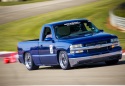
-10 off each valve cover to a vented catch can is how I have the PCV setup with the KB and speed density tune on my truck. I do get some smell from the can and some steam out of the hood at a stop. This is a solution I thought of to recirculate some of the blowby at idle but allow max venting at wot...
This obviously would not work running a MAF as it would introduce unmetered air behind the throttle body.
So the blue line goes into the actual blower port, sitting behind the TB on the snout. So im assuming "post throttle body" or "pre blower"
I am indeed running a MAF unless my tuner decides to go SD, but for my purposes we are just trying to get her started.
I talked to Atomic and so far he recommended both valve covers going to the vented catch can, and nothing going back into the intake tube/manifold.
Im definitely gonna have to look into a better catch can and some actual 10AN bunged valve covers
here is how mine is installed. The blue line goes to the top of the manifold where the old pcv line from the driverside valve cover used to go to. Mighty mouse has the diagrams on their page. I have the pcv version catch can from them.
Edit... Before i just had both valve covers with breather/filters and i had that "gas smell" at idle and stop lights and after a wot pull. After i put the can on i no longer had that smell.
Last edited by 05GMC4.8; 06-12-2019 at 05:42 PM.
Reason: Additional info added
So im still working on getting the bugs worked out, we managed to start it last week, and after talking to a local perfomance shop over the weekend.
They recommended i just cap everything off on the blower, and run a breather tank to each valve cover.
I ordered them today, so hopefully i can show you guys some pics later.
here is how mine is installed. The blue line goes to the top of the manifold where the old pcv line from the driverside valve cover used to go to. Mighty mouse has the diagrams on their page. I have the pcv version catch can from them.
Edit... Before i just had both valve covers with breather/filters and i had that "gas smell" at idle and stop lights and after a wot pull. After i put the can on i no longer had that smell.
Your setup is probably closest related to mine.
I have two breather tanks now, one on each VC.
What made you switch, and when you were on the breather tanks, were you MAF or SD tuned?
I invested in the breather tanks, so idk if its smart to keep it, or spend more money and try figuring out the catch can option with PCV system still working.
 06-12-2019, 08:29 AM