Schematics, Pinoouts, Training Materials, Technical Documents


 02-25-2012, 08:25 PM
#32
Diagnostic Tips For Diagnosing High Speed Lan Concerns - keywords ABS brake comm crank DTC GMLAN indicators IPC lamp light no speed start
Subject: Diagnostic Tips For Diagnosing High Speed Lan Concerns
Models:
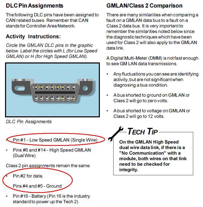
The data link connector (DLC) allows a scan tool to communicate with the high speed GMLAN serial data modules. The serial data is transmitted on 2 twisted wires that allow speed up to 500 Kb/s. The twisted pair is terminated with two 120-ohm resistors, one is internal to the engine control module (ECM) and the other is after the electronic brake control module (EBCM), or if equipped, the suspension control module. If a communication signal is lost, the software application will set a no communication code ("U" code) against the respective control module. This code is mapped on the Tech 2 screen as a code against the physical device. Note: a loss of serial data DTC does not represent a failure of the module that the code is set in. If you experience a current or intermittent loss of communication with a high speed LAN module, the following diagnostic tips may help you locate the source of the concern.


INTERMITTENT HIGH SPEED LAN CONCERNS
If the high speed lan communication concern is intermittent or you get a vehicle that returns with multiple "U "codes, use the following test to try and isolate the area of concern.


Subject: Diagnostic Tips For Diagnosing High Speed Lan Concerns
Models:
2007-2010 Cadillac Escalade, ESV, EXT
2007-2010 Chevrolet Avalanche, Silverado, Suburban, Tahoe
2007-2010 GMC Sierra, Yukon, Yukon Denali, Yukon XL, Yukon Denali XL
2008-2010 Hummer H2
With one or more of the following DTCs U1814 U2100 U2099 U0100 U0101 U0102 U0121 U0140 U2100 U0073
Condition/Concern:2007-2010 Chevrolet Avalanche, Silverado, Suburban, Tahoe
2007-2010 GMC Sierra, Yukon, Yukon Denali, Yukon XL, Yukon Denali XL
2008-2010 Hummer H2
With one or more of the following DTCs U1814 U2100 U2099 U0100 U0101 U0102 U0121 U0140 U2100 U0073
The data link connector (DLC) allows a scan tool to communicate with the high speed GMLAN serial data modules. The serial data is transmitted on 2 twisted wires that allow speed up to 500 Kb/s. The twisted pair is terminated with two 120-ohm resistors, one is internal to the engine control module (ECM) and the other is after the electronic brake control module (EBCM), or if equipped, the suspension control module. If a communication signal is lost, the software application will set a no communication code ("U" code) against the respective control module. This code is mapped on the Tech 2 screen as a code against the physical device. Note: a loss of serial data DTC does not represent a failure of the module that the code is set in. If you experience a current or intermittent loss of communication with a high speed LAN module, the following diagnostic tips may help you locate the source of the concern.
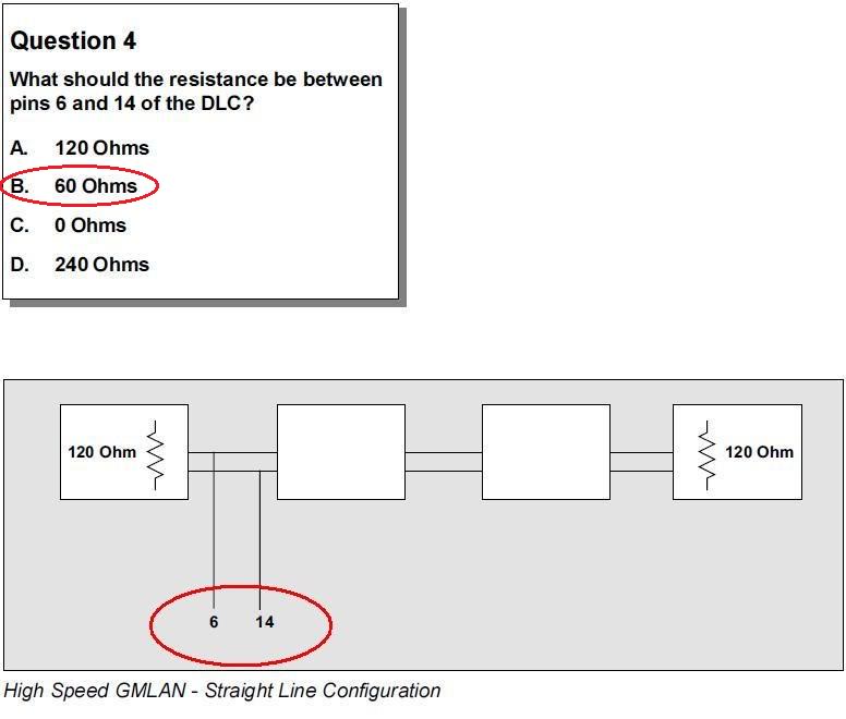
- If the Tech 2 cannot communicate with any high speed lan modules check for proper terminal drag at the DLC pins 6 & 14 using test probe J-35616-C. Also verify the high speed lan circuit integrity by measuring the resistance across 6 & 14 using a DVOM, with the battery disconnected. A normal reading would be 60 ohms +/- 3 ohms. A reading something less than 60 ohms would indicate that high speed lan circuits are shorted together (terminating resistor, internal in a module, circuits shorted together, etc). If the reading is something higher than 60 ohms this indicates high resistance in the high speed lan circuits (terminating resistor, internal in a module, open high speed lan circuit, etc.)
- If the high speed lan circuit integrity is good and the scan tool still will not communicate with any high speed lan modules, try either or both of the following tips to help isolate/break up parts of the high speed lan circuit/modules:
- Remove the battery feeds from each high speed lan module one at a time while monitoring the Tech 2 to see if communications return with the other modules.
- And/Or break the high speed lan modules into two separate circuits by removing connector C3(X3) from the back of the left I/P junction block. See steps below:
- a) Locate the left IP junction block, and remove the cover.
- b) Squeeze the locator tabs and remove junction block from holding bracket.
- c) Locate the Green C3(X3) connector that is located on the back of the junction block
- d) Remove the C3(X3) connector from the bottom of the IP fuse block, This will isolate the high speed lan modules in two halves.
INTERMITTENT HIGH SPEED LAN CONCERNS
If the high speed lan communication concern is intermittent or you get a vehicle that returns with multiple "U "codes, use the following test to try and isolate the area of concern.
� a) Shut vehicle off, remove key, and open driver's door and wait 2 minutes.
� b) Locate the DLC connector and probe pins 6 & 14 using the proper test terminals contained in terminal test kit J-35616-C.
� c) Using a DVOM, measure the resistance across pins 6 & 14 at the dlc connector. The resistance should be around 60 ohms and remain steady.
� d) Have an assistant wiggle test the wiring at each high speed lan module while monitoring the DVOM reading looking for any type of fluctuation. If the reading varies while wiggle testing the wiring, check for proper terminal drag/terminal to wire crimp/ and circuit integrity at the effected module and repair as needed.
� d) Have an assistant wiggle test the wiring at each high speed lan module while monitoring the DVOM reading looking for any type of fluctuation. If the reading varies while wiggle testing the wiring, check for proper terminal drag/terminal to wire crimp/ and circuit integrity at the effected module and repair as needed.

 02-25-2012, 10:26 PM
#34

Awsome!!! Thanks for the help
I am trying to help Chris with this issue. We have something like 60.9 ohms. I can communmicate with the ECM and TCM but the BCM will not communicate with the Tech2.
It will alow me to get module info but I can not get it anything else with the BCM to function. Doors, lights and so on.
I can go biderectional to the ECM and TCM but when I try to retrive the BCM it will not comunicate. It will let me see the module info I just can't seem to talk to it.
Its 2007 Silverado GMT900 E38/T42 4 Speed.
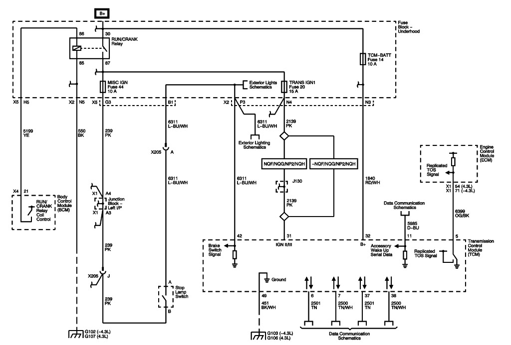
Would like to see how the Trans and BCM talk with each other. I can see the gear engauge on the scan tool and the brake switch open and close.
U0140
P0315
are the only 2 active codes on the Tech2
But I also get these codes with my EFI LIVE and some of the same stuff shows up on my Snap on scanner.
I can not pull the ECM Tune either most likely because of the DTC faults
Perhaps I need to just get a bench harness adapter.
I was able to get the TCM info though if that means anything...
Diagnostic Trouble Codes
P0230 "Fuel Pump Primary Circuit"
P0315 "Crankshaft Position System Variation Not Learned"
P0449 "Evaporative Emission (EVAP) Vent Solenoid Control Circuit"
P0452 "Fuel Tank Pressure (FTP) Sensor Circuit Low Voltage"
P0463 "Fuel Level Sensor 1 Circuit High Voltage"
P069E "Fuel Pump Control Module (FPCM) Requested MIL Illumination"
P025A EPA ($18) "Transmission Control Module (TCM)"
P0230 "Fuel Pump Primary Circuit"
P0315 "Crankshaft Position System Variation Not Learned"
P0449 "Evaporative Emission (EVAP) Vent Solenoid Control Circuit"
P0452 "Fuel Tank Pressure (FTP) Sensor Circuit Low Voltage"
P0463 "Fuel Level Sensor 1 Circuit High Voltage"
P069E "Fuel Pump Control Module (FPCM) Requested MIL Illumination"
P025A EPA Pending ($18) "Transmission Control Module (TCM)"
P0230 "Fuel Pump Primary Circuit"
P0315 "Crankshaft Position System Variation Not Learned"
P0449 "Evaporative Emission (EVAP) Vent Solenoid Control Circuit"
P0452 "Fuel Tank Pressure (FTP) Sensor Circuit Low Voltage"
P0463 "Fuel Level Sensor 1 Circuit High Voltage"
P069E "Fuel Pump Control Module (FPCM) Requested MIL Illumination"
U0140 "Lost Communication With Body Control Module"
U0140 "Lost Communication With Body Control Module"
On a side note I have been busy at work lately and have not had the time to get the parts and send the cluster out...
Thanks for any wireing or other diagnostic help you can provide!!!
I am trying to help Chris with this issue. We have something like 60.9 ohms. I can communmicate with the ECM and TCM but the BCM will not communicate with the Tech2.
It will alow me to get module info but I can not get it anything else with the BCM to function. Doors, lights and so on.
I can go biderectional to the ECM and TCM but when I try to retrive the BCM it will not comunicate. It will let me see the module info I just can't seem to talk to it.
Its 2007 Silverado GMT900 E38/T42 4 Speed.
Would like to see how the Trans and BCM talk with each other. I can see the gear engauge on the scan tool and the brake switch open and close.
U0140
P0315
are the only 2 active codes on the Tech2
But I also get these codes with my EFI LIVE and some of the same stuff shows up on my Snap on scanner.
I can not pull the ECM Tune either most likely because of the DTC faults
Perhaps I need to just get a bench harness adapter.
I was able to get the TCM info though if that means anything...
Diagnostic Trouble Codes
P0230 "Fuel Pump Primary Circuit"
P0315 "Crankshaft Position System Variation Not Learned"
P0449 "Evaporative Emission (EVAP) Vent Solenoid Control Circuit"
P0452 "Fuel Tank Pressure (FTP) Sensor Circuit Low Voltage"
P0463 "Fuel Level Sensor 1 Circuit High Voltage"
P069E "Fuel Pump Control Module (FPCM) Requested MIL Illumination"
P025A EPA ($18) "Transmission Control Module (TCM)"
P0230 "Fuel Pump Primary Circuit"
P0315 "Crankshaft Position System Variation Not Learned"
P0449 "Evaporative Emission (EVAP) Vent Solenoid Control Circuit"
P0452 "Fuel Tank Pressure (FTP) Sensor Circuit Low Voltage"
P0463 "Fuel Level Sensor 1 Circuit High Voltage"
P069E "Fuel Pump Control Module (FPCM) Requested MIL Illumination"
P025A EPA Pending ($18) "Transmission Control Module (TCM)"
P0230 "Fuel Pump Primary Circuit"
P0315 "Crankshaft Position System Variation Not Learned"
P0449 "Evaporative Emission (EVAP) Vent Solenoid Control Circuit"
P0452 "Fuel Tank Pressure (FTP) Sensor Circuit Low Voltage"
P0463 "Fuel Level Sensor 1 Circuit High Voltage"
P069E "Fuel Pump Control Module (FPCM) Requested MIL Illumination"
U0140 "Lost Communication With Body Control Module"
U0140 "Lost Communication With Body Control Module"
On a side note I have been busy at work lately and have not had the time to get the parts and send the cluster out...
Thanks for any wireing or other diagnostic help you can provide!!!
 02-26-2012, 09:21 AM
#37
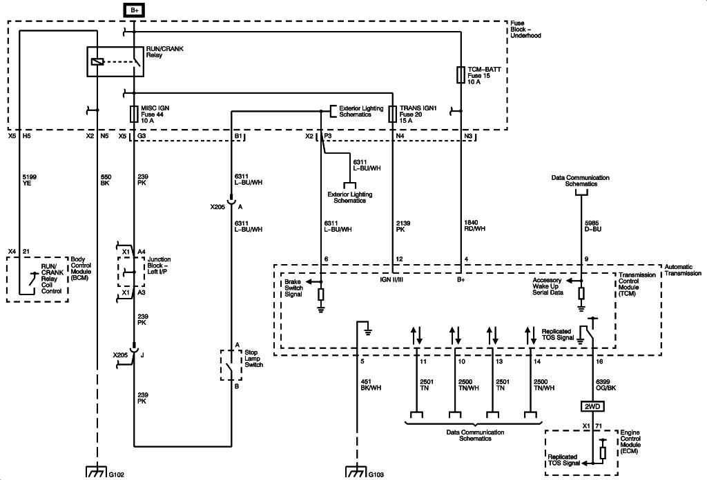
Engine Controls Schematics
Figure 1: Module Power, Ground and Serial Data
Figure 2: 5-Volt and Low Reference
Figure 3: Engine Data Sensors - Pressure and Temperature
Figure 4: Engine Data Sensors - Heated Oxygen Sensors
Figure 5: Engine Data Sensors - Throttle Controls
Figure 6: Ignition Controls - Ignition System Coils 1,3,5 and 7
Figure 7: Ignition Controls - Ignition System Coils 2,4,6 and 8
Figure 8: Ignition Controls - Sensors
Figure 9: Fuel Controls - Fuel Pump Controls (L76, L92, LH6, LY2, or LY5)
Figure 10: Fuel Controls - Fuel Pump Controls (LC9, LY6, or LMG)
Figure 11: Fuel Controls - Fuel Injectors
Figure 12: Fuel Controls - EVAP Controls
Figure 13: Controlled/Monitored Subsystem References
Figure 1: Module Power, Ground and Serial Data
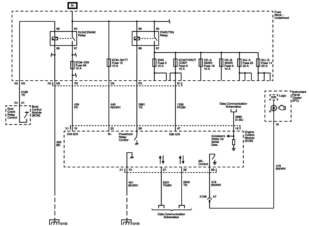
Figure 2: 5-Volt and Low Reference
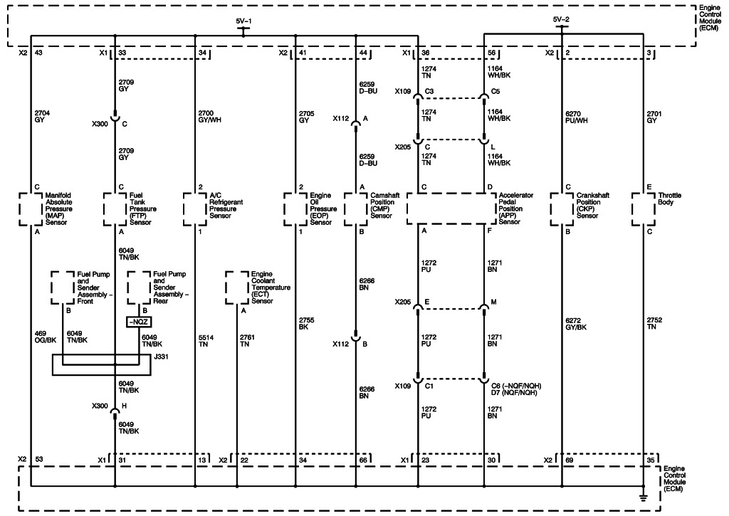
Figure 3: Engine Data Sensors - Pressure and Temperature
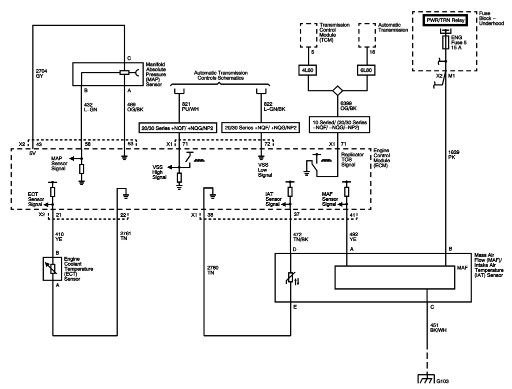
Figure 4: Engine Data Sensors - Heated Oxygen Sensors
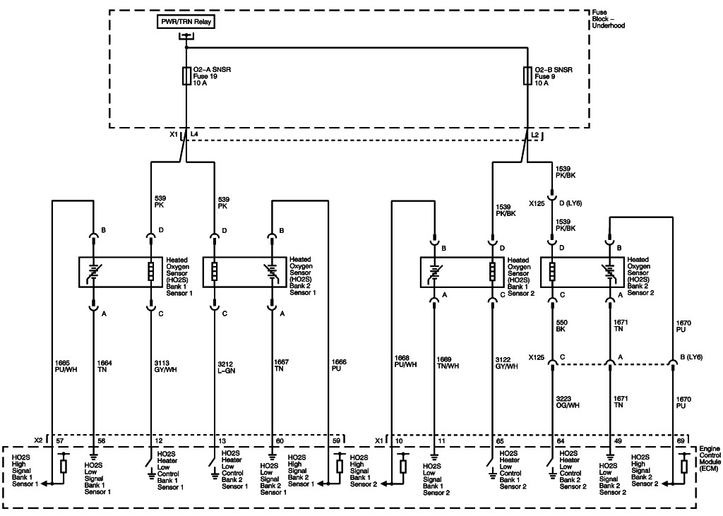
Figure 5: Engine Data Sensors - Throttle Controls
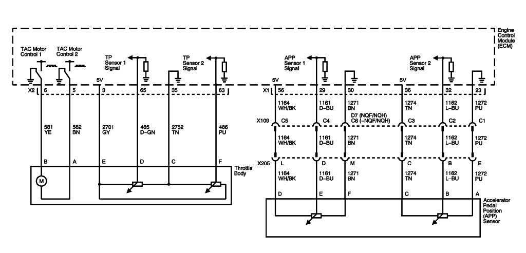
Figure 6: Ignition Controls - Ignition System Coils 1,3,5 and 7
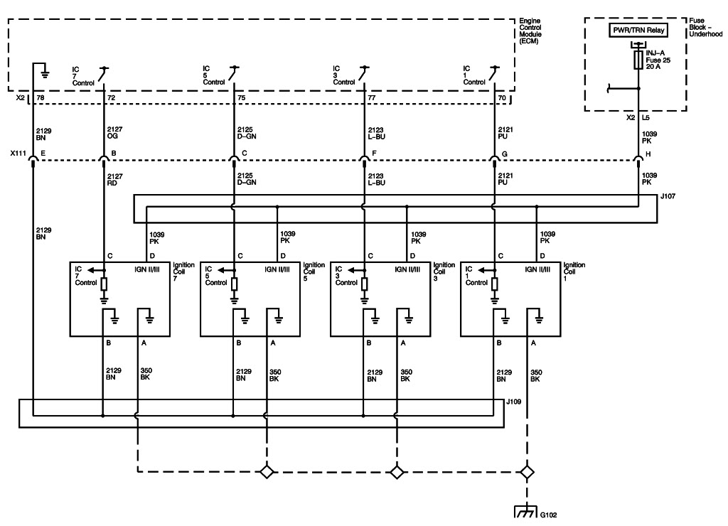
Figure 7: Ignition Controls - Ignition System Coils 2,4,6 and 8
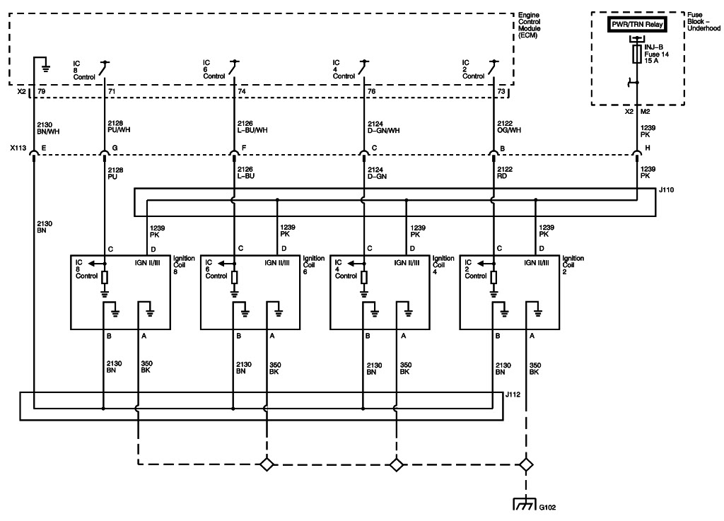
Figure 8: Ignition Controls - Sensors
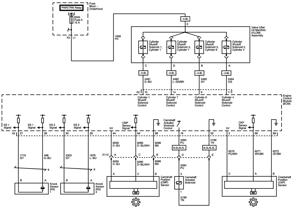
Figure 9: Fuel Controls - Fuel Pump Controls (L76, L92, LH6, LY2, or LY5)
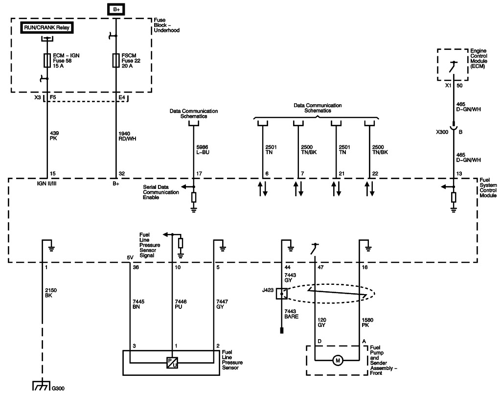
Figure 10: Fuel Controls - Fuel Pump Controls (LC9, LY6, or LMG)
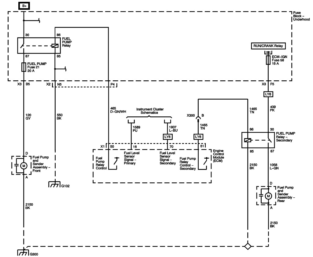
Figure 11: Fuel Controls - Fuel Injectors
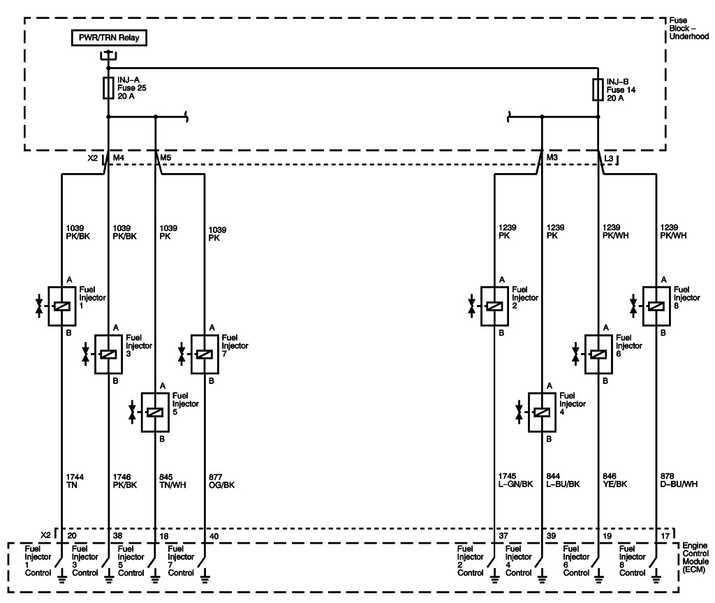
Figure 12: Fuel Controls - EVAP Controls
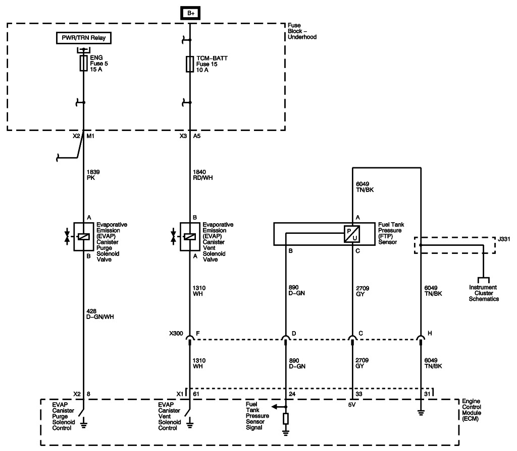
Figure 13: Controlled/Monitored Subsystem References
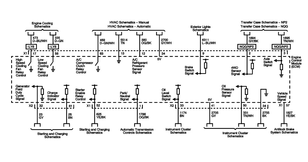
Figure 1: Module Power, Ground and Serial Data
Figure 2: 5-Volt and Low Reference
Figure 3: Engine Data Sensors - Pressure and Temperature
Figure 4: Engine Data Sensors - Heated Oxygen Sensors
Figure 5: Engine Data Sensors - Throttle Controls
Figure 6: Ignition Controls - Ignition System Coils 1,3,5 and 7
Figure 7: Ignition Controls - Ignition System Coils 2,4,6 and 8
Figure 8: Ignition Controls - Sensors
Figure 9: Fuel Controls - Fuel Pump Controls (L76, L92, LH6, LY2, or LY5)
Figure 10: Fuel Controls - Fuel Pump Controls (LC9, LY6, or LMG)
Figure 11: Fuel Controls - Fuel Injectors
Figure 12: Fuel Controls - EVAP Controls
Figure 13: Controlled/Monitored Subsystem References
Last edited by CalEditor@PCMCalibrators; 02-26-2012 at 02:59 PM.
02-26-2012, 09:27 AM
#38
2007 GMT-900
Body Control System Description and Operation
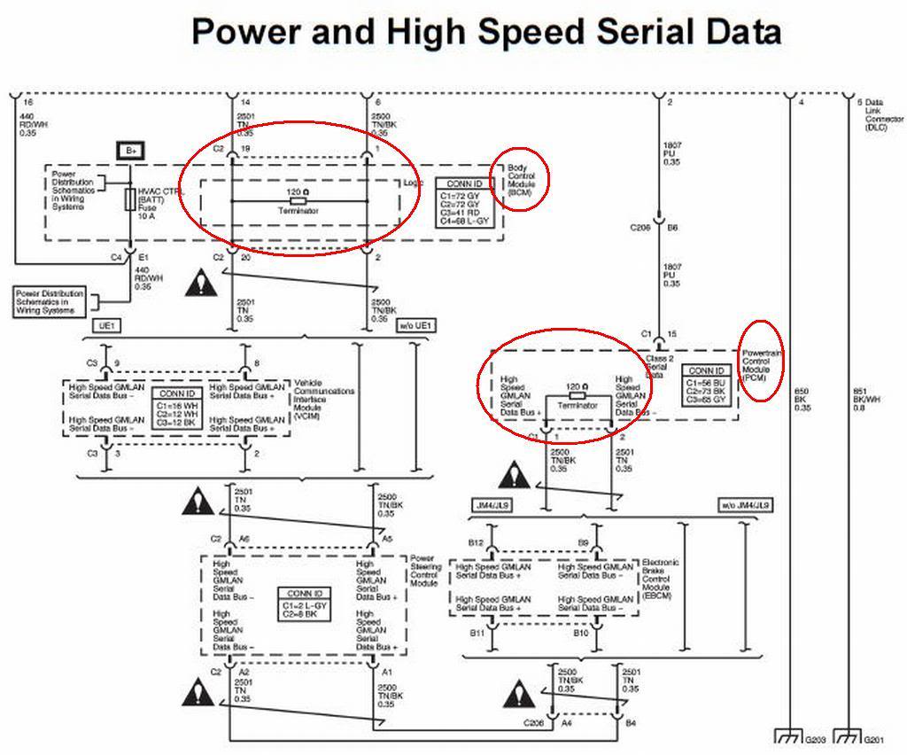
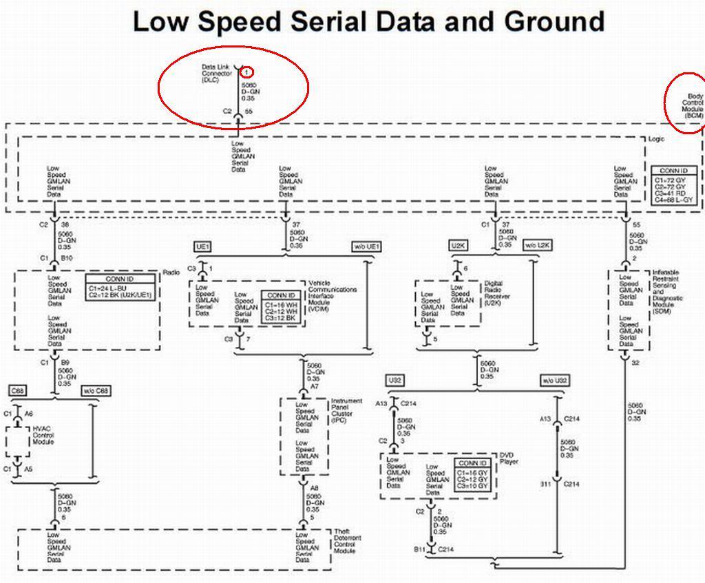
The body control system consists of the body control module (BCM), communications, and various input and outputs. Some inputs, outputs and messages require other modules to interact with the BCM. The BCM also has discrete input and output terminals to control the vehicle's body functions. The BCM is wired to the GMLAN high speed serial data buss and the GMLAN low speed serial data buss and acts as a gateway between them. If the BCM does not communicate the vehicle will not start due to the inability of the engine control module (ECM)/powertrain control module (PCM) and theft deterrent module (TDM) to communicate without the BCM providing the gateway function.
Power Mode Master
This vehicles body control module (BCM) functions as the power mode master (PMM). The ignition switch is a low current switch with multiple discrete ignition switch signals to the PMM for determination the power mode that will be sent over the serial data circuits to the other modules that need this information, and so the PMM will activate relays and other direct outputs of the PMM as needed. Refer to Power Mode Description and Operation for a complete description of power mode functions.
Serial Data Gateway
The body control module (BCM) in this vehicle functions as a gateway or translator. The purpose of the gateway is to translate serial data messages between the GMLAN high speed buss and the GMLAN low speed buss for communication between the various modules. The gateway will interact with each network according to that network's transmission protocol.
One example of this necessary communication is the communication between the engine control module (ECM)/powertrain control module (PCM) which is high speed serial data and Theft Deterrent Module which is low speed serial data. If these modules can not exchange information, the vehicle will not start.
Communication between the BCM and a scan tool can be on the high speed GMLAN network or low speed GMLAN network. If one network is lost, the BCM can still communicate with the scan tool. A lost communication DTC typically is set in modules other than the module with a communication failure.
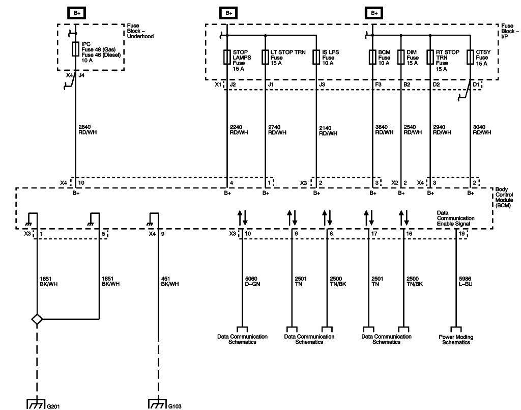
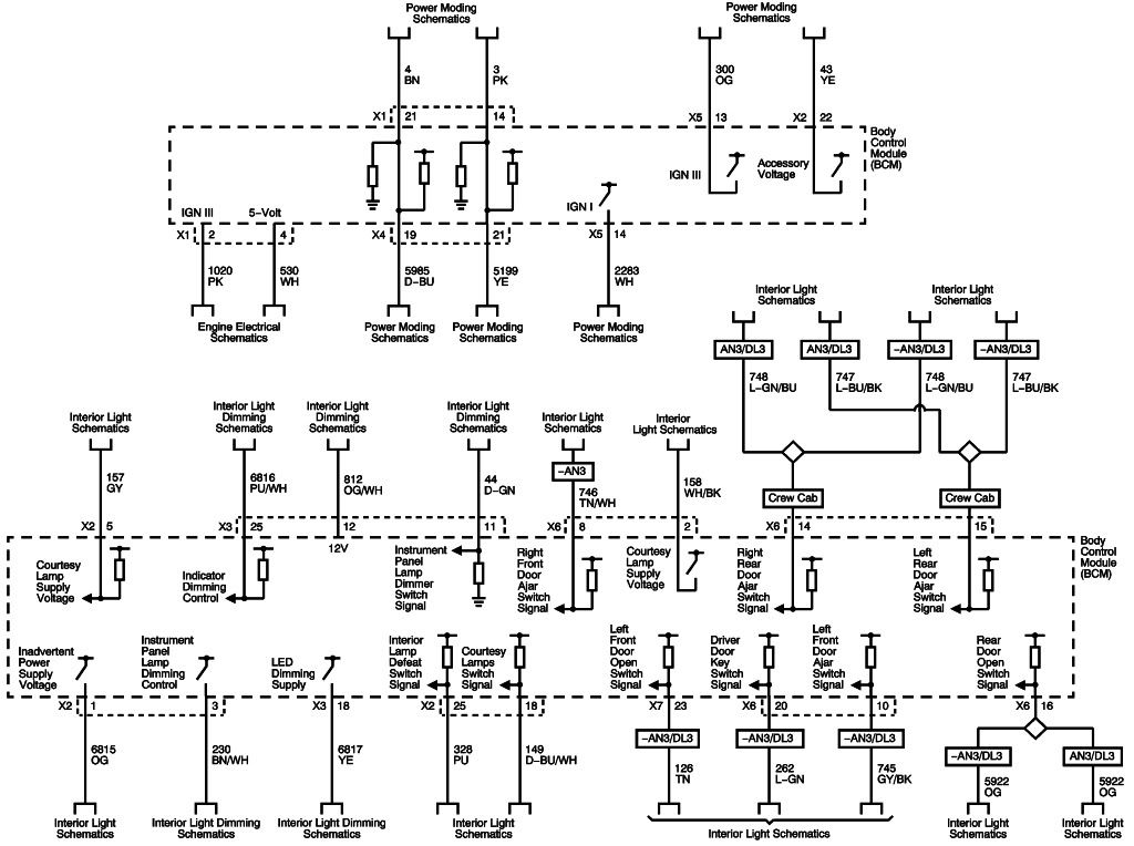
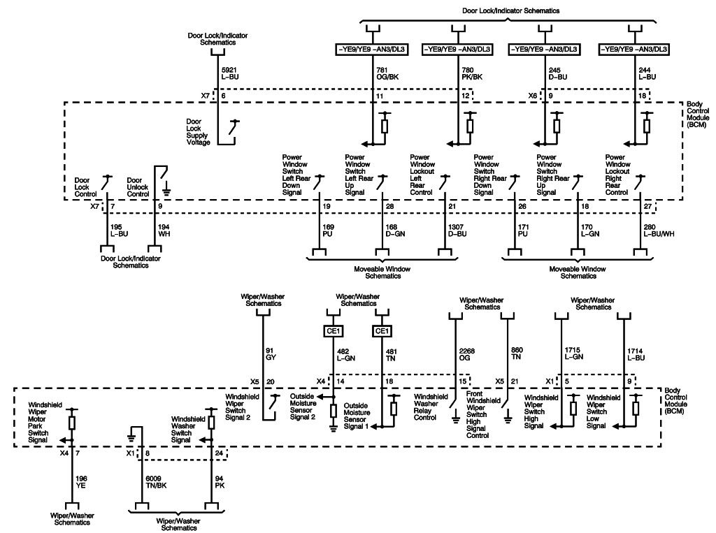
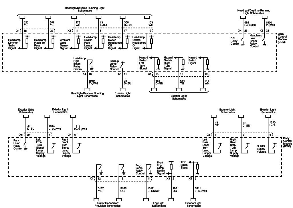
Body Control Module
The various body control module (BCM) input and output circuits are described in the corresponding functional areas indicated on the BCM electrical schematics. Some BCM functions with the subsystems may be as a gateway only or as an enable for the system. The BCM related systems/subsystems include, but are not limited to the following:
Body Control System Description and Operation
The body control system consists of the body control module (BCM), communications, and various input and outputs. Some inputs, outputs and messages require other modules to interact with the BCM. The BCM also has discrete input and output terminals to control the vehicle's body functions. The BCM is wired to the GMLAN high speed serial data buss and the GMLAN low speed serial data buss and acts as a gateway between them. If the BCM does not communicate the vehicle will not start due to the inability of the engine control module (ECM)/powertrain control module (PCM) and theft deterrent module (TDM) to communicate without the BCM providing the gateway function.
Power Mode Master
This vehicles body control module (BCM) functions as the power mode master (PMM). The ignition switch is a low current switch with multiple discrete ignition switch signals to the PMM for determination the power mode that will be sent over the serial data circuits to the other modules that need this information, and so the PMM will activate relays and other direct outputs of the PMM as needed. Refer to Power Mode Description and Operation for a complete description of power mode functions.
Serial Data Gateway
The body control module (BCM) in this vehicle functions as a gateway or translator. The purpose of the gateway is to translate serial data messages between the GMLAN high speed buss and the GMLAN low speed buss for communication between the various modules. The gateway will interact with each network according to that network's transmission protocol.
One example of this necessary communication is the communication between the engine control module (ECM)/powertrain control module (PCM) which is high speed serial data and Theft Deterrent Module which is low speed serial data. If these modules can not exchange information, the vehicle will not start.
Communication between the BCM and a scan tool can be on the high speed GMLAN network or low speed GMLAN network. If one network is lost, the BCM can still communicate with the scan tool. A lost communication DTC typically is set in modules other than the module with a communication failure.
Body Control Module
The various body control module (BCM) input and output circuits are described in the corresponding functional areas indicated on the BCM electrical schematics. Some BCM functions with the subsystems may be as a gateway only or as an enable for the system. The BCM related systems/subsystems include, but are not limited to the following:
- Antilock Brake System (ABS)�Refer to ABS Description and Operation .
- Automatic Day-Night Mirror�Refer to Automatic Day-Night Mirror Description and Operation .
- Cruise Control System�Refer to Cruise Control Description and Operation .
- Electrical Power Management (EPM)�Refer to Electrical Power Management Description and Operation .
- Exterior Lighting�Refer to Exterior Lighting Systems Description and Operation .
- Horn System�Refer to Horns System Description and Operation .
- HVAC�Refer to Air Delivery Description and Operation and Air Temperature Description and Operation .
- Instrument Cluster Indicator Control�Refer to Instrument Cluster Description and Operation .
- Interior Lighting�Refer to Interior Lighting Systems Description and Operation .
- Power Door Lock System�Refer to Power Door Locks Description and Operation .
- Rear Window Defogger System�Refer to Rear Window Defogger Description and Operation .
- Redundant Steering Wheel Controls�Refer to Steering Wheel Controls Description and Operation .
- Remote Function Actuation (RFA) Control�Refer to Keyless Entry System Description and Operation .
- Retained Accessory Power (RAP)�Refer to Retained Accessory Power Description and Operation .
- Shift Lock Control System�Refer to Automatic Transmission Shift Lock Control Description and Operation .
- Starting System�Refer to Starting System Description and Operation .
- Supplemental Inflatable Restraint (SIR) System�Refer to SIR System Description and Operation .
- Theft Deterrent�Refer to Content Theft Deterrent (CTD) Description and Operation .
- Tire Pressure Monitor (TPM) System�Refer to Tire Pressure Monitor Description and Operation .
- Wiper/Washer System Functions�Refer to Wiper/Washer System Description and Operation .
02-26-2012, 09:45 AM
#39
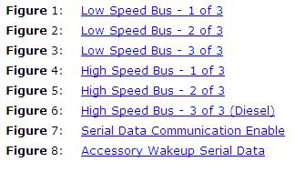
Figure 1: Low Speed Bus - 1 of 3
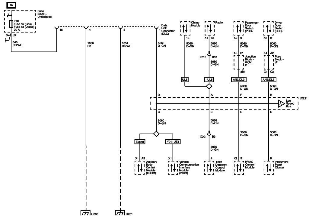
Figure 2: Low Speed Bus - 2 of 3
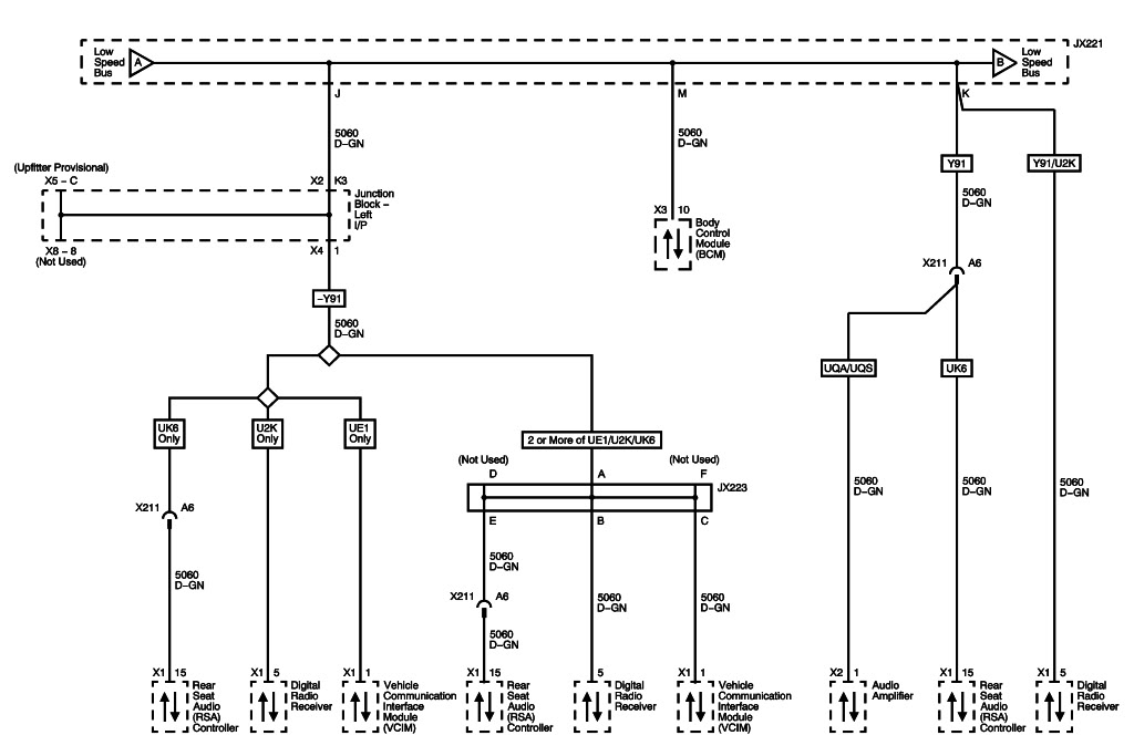
Figure 3: Low Speed Bus - 3 of 3
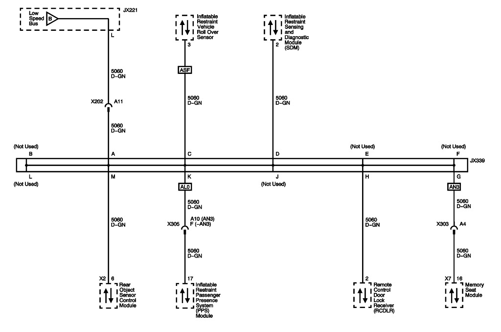
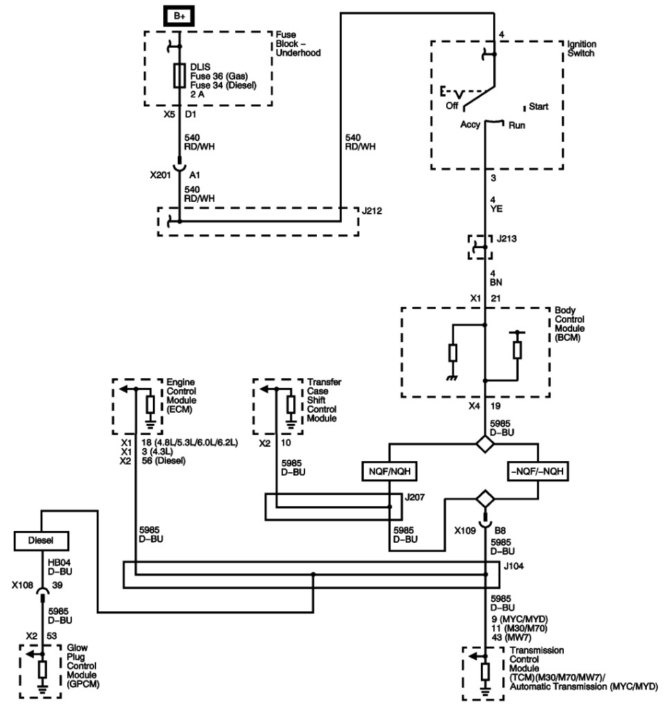
Figure 4: High Speed Bus - 1 of 3
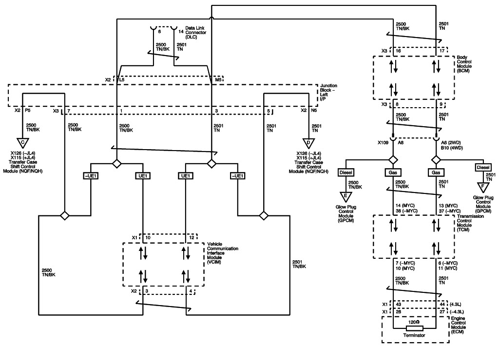
Figure 5: High Speed Bus - 2 of 3
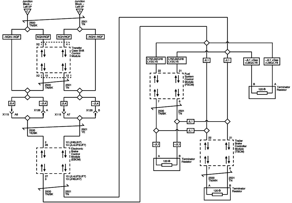
Figure 6: High Speed Bus - 3 of 3 (Diesel)
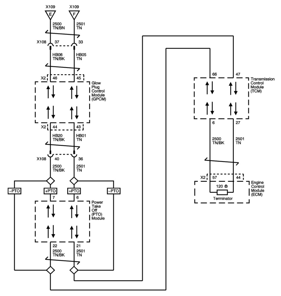
Figure 7: Serial Data Communication Enable
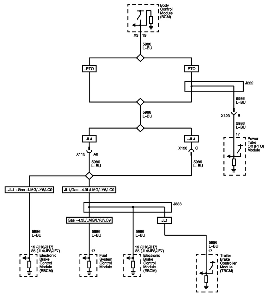
Figure 8: Accessory Wakeup Serial Data
Last edited by CalEditor@PCMCalibrators; 02-26-2012 at 03:03 PM.