90mm ETC Improved Blade Range Mod
 11-26-2006, 12:24 PM
#1
This applies to the Corvette LS2 90mm throttle body conversion on trucks originally equipped with the 78mm ETC throttle body. It assumes that you are using the 2002 TAC module. This involves internal modifications to the circuit board of the throttle position sensor so it may not be for everyone. Someone with expertise in electronics may be able to design the necessary circuitry for a completely external solution. But it would be more complicated than just adding a couple of resistors. I have tried many different approaches. I was able to achieve a 95 - 96% blade opening with these modifications. This meets or exceeds the maximum opening seen on a stock truck setup. Any modifications are done at your own risk and I don�t accept any responsibility for the accuracy, correctness or completeness of the described method.
You will need the following supplies: 20 gauge wire, electrical solder and flux, flux cleaner, soldering iron, new cover screws for the TB(I had some PC drive mounting screws laying around that fit perfectly-not the self-tappers), heat shrink, 2 single weather pack connector sets if desired or 1 connector and an additional pin to add to the connector on the adapter harness, blue loctite, 500 ohm trim pot, small resistors as required(e.g. 15, 33, 47, 100, 220, 330), ohmmeter.
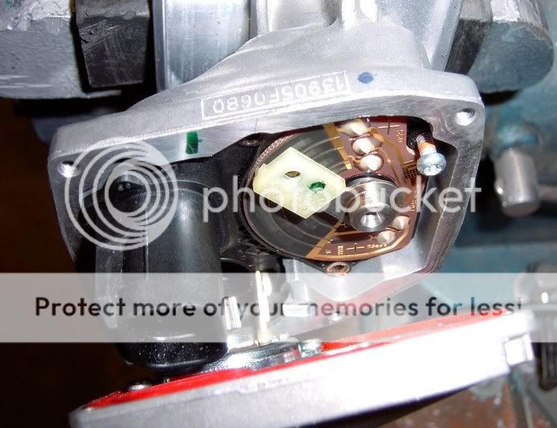
In order to get into the TB cleanly you will need a Torx Plus � Tamper Resistant bit. Apparently these are patented and you need a license to get them. Otherwise just use your favorite method to remove the screws. I just slotted them and they turned out easily with a screwdriver. Start lifting up the cover on the TB from the bottom side where the connector is located. Slide it up over the connector. The leads to the motor are spot welded so the cover won�t come completely off. You will need to drill a single small hole in the cover for the wire that will be added to the circuit board. I used a 20 gauge wire. A smaller wire may be used for the short jumper.
The purpose of the additional wire is to create separate high (5V) reference circuits for each of the two sensors. This allows individual calibration of the sensor outputs.
For soldering: I placed a small amount of soldering flux on the gold trace and the wire to be connected, coat the wire with solder, create a clean drop of solder on the tip of the soldering iron, transfer the bead of solder to the gold trace, then attach the wire to the bead of solder. To avoid damage the iron should only contact the circuit board momentarily. You can use some flux cleaner for circuit boards to clean things up when you are done.
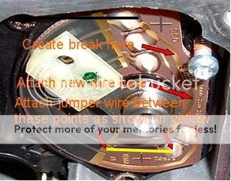
The following steps refer to the attached photos:
1) Create a break in the common 5V reference circuit as shown. Just scratch
away some of the gold trace. You can test for continuity across the gap to
ensure that the break is complete.
2) Attach the new wire to the gold trace where indicated = 5-7% more blade opening.
3) Solder the jumper as shown = another 5% blade opening. You will have to
scratch off some of the protective coating on the existing solder joint in order
to do this.
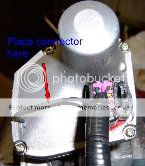
Route the new wire through the hole in the cover if you have not already done so. Replace the cover while carefully pulling any excess wire through the hole. Ensure that the wire is routed internally in a manner that does not interfere with the movement of the shaft/wiper assembly. I used some epoxy to stabilize/secure the wire to the circuit board and to insulate/protect the new solder joints. You may apply some blue loctite to the new cover screws if desired.
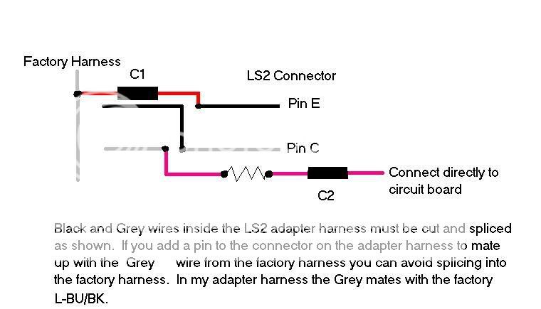
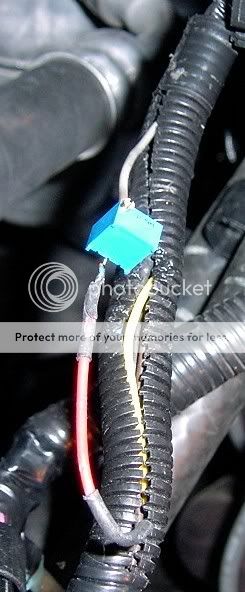
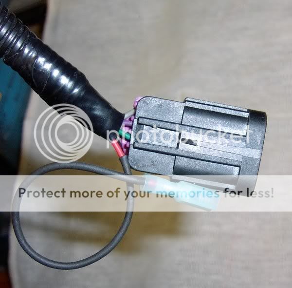
Make the wiring connections as per the attached illustration. This assumes that your adapter harness matches mine with respect to wire color/pin assignments. You can use connectors where shown if you don�t wish to make permanent connections. This will allow easy removal of the adapter harness.
Calibration:
Method1) With the key in the run position, have someone hold the accelerator pedal to the floor. Adjust the resistance on the trim pot until maximum blade opening is just achieved. Next, move the pedal through its entire range to ensure that sensor correlation is OK (i.e REP mode is not triggered). I ended up with 375 ohms Your results may vary due to the other modifications that I made to my TB for testing purposes.
Method 2) Ideally, you would use logging software for this adjustment. If you log the ETCTPS1% and ETCTPS2% parameters, you should adjust the resistance until ETCTPS1% just reaches the maximum (39.2% with EFILive). ETCTPS2% should below or just at the maximum. If TPS2% reaches the maximum prior to TPS1%, it will limit blade opening to whatever TPS1% represents at that point. No big problem though if TPS1% is at say 38.8%, and TPS2% is just at 39.2%. Close enough.
Once you have determined the optimal resistance, you may measure it with an ohmmeter, replace the trim pot with fixed resistors of the same total value, and tuck everything back inside the wire loom. Might want to do a little test driving and re-logging for a few days before replacing the trim pot.
You will need the following supplies: 20 gauge wire, electrical solder and flux, flux cleaner, soldering iron, new cover screws for the TB(I had some PC drive mounting screws laying around that fit perfectly-not the self-tappers), heat shrink, 2 single weather pack connector sets if desired or 1 connector and an additional pin to add to the connector on the adapter harness, blue loctite, 500 ohm trim pot, small resistors as required(e.g. 15, 33, 47, 100, 220, 330), ohmmeter.
In order to get into the TB cleanly you will need a Torx Plus � Tamper Resistant bit. Apparently these are patented and you need a license to get them. Otherwise just use your favorite method to remove the screws. I just slotted them and they turned out easily with a screwdriver. Start lifting up the cover on the TB from the bottom side where the connector is located. Slide it up over the connector. The leads to the motor are spot welded so the cover won�t come completely off. You will need to drill a single small hole in the cover for the wire that will be added to the circuit board. I used a 20 gauge wire. A smaller wire may be used for the short jumper.
The purpose of the additional wire is to create separate high (5V) reference circuits for each of the two sensors. This allows individual calibration of the sensor outputs.
For soldering: I placed a small amount of soldering flux on the gold trace and the wire to be connected, coat the wire with solder, create a clean drop of solder on the tip of the soldering iron, transfer the bead of solder to the gold trace, then attach the wire to the bead of solder. To avoid damage the iron should only contact the circuit board momentarily. You can use some flux cleaner for circuit boards to clean things up when you are done.
The following steps refer to the attached photos:
1) Create a break in the common 5V reference circuit as shown. Just scratch
away some of the gold trace. You can test for continuity across the gap to
ensure that the break is complete.
2) Attach the new wire to the gold trace where indicated = 5-7% more blade opening.
3) Solder the jumper as shown = another 5% blade opening. You will have to
scratch off some of the protective coating on the existing solder joint in order
to do this.
Route the new wire through the hole in the cover if you have not already done so. Replace the cover while carefully pulling any excess wire through the hole. Ensure that the wire is routed internally in a manner that does not interfere with the movement of the shaft/wiper assembly. I used some epoxy to stabilize/secure the wire to the circuit board and to insulate/protect the new solder joints. You may apply some blue loctite to the new cover screws if desired.
Make the wiring connections as per the attached illustration. This assumes that your adapter harness matches mine with respect to wire color/pin assignments. You can use connectors where shown if you don�t wish to make permanent connections. This will allow easy removal of the adapter harness.
Calibration:
Method1) With the key in the run position, have someone hold the accelerator pedal to the floor. Adjust the resistance on the trim pot until maximum blade opening is just achieved. Next, move the pedal through its entire range to ensure that sensor correlation is OK (i.e REP mode is not triggered). I ended up with 375 ohms Your results may vary due to the other modifications that I made to my TB for testing purposes.
Method 2) Ideally, you would use logging software for this adjustment. If you log the ETCTPS1% and ETCTPS2% parameters, you should adjust the resistance until ETCTPS1% just reaches the maximum (39.2% with EFILive). ETCTPS2% should below or just at the maximum. If TPS2% reaches the maximum prior to TPS1%, it will limit blade opening to whatever TPS1% represents at that point. No big problem though if TPS1% is at say 38.8%, and TPS2% is just at 39.2%. Close enough.
Once you have determined the optimal resistance, you may measure it with an ohmmeter, replace the trim pot with fixed resistors of the same total value, and tuck everything back inside the wire loom. Might want to do a little test driving and re-logging for a few days before replacing the trim pot.
Last edited by DrX; 11-28-2006 at 10:43 PM.
 11-26-2006, 01:07 PM
#2
TECH Junkie
All I can say is that,I'm glad a ETC 90mm throttle body was not an option when I did my conversion 3 years ago and that the problems I encountered converting to cable operation were small conpared to what you guys are going thru.
 Great job DrX.


Trending Topics
11-26-2006, 10:34 PM
#8
I still want to get a few miles on this before I can claim 100% success. Still see some intermittent fluctuations in one of the sensor outputs while driving. Usually under steady light throttle/coast conditions(looks like a single or series of spikes in the log of ETCTP). This will trigger REP mode if it persists for more than 1 sec or there is greater than 7.5% difference between the absolute throttle positions indicated by the 2 sensors. Otherwise throttle responsiveness is good. I don't see any issues when logging the sensor outputs when the vehicle is stationary or the engine is off. Hopefully, not a loose connection inside the TB or poor contact between the wiper and potentiometer film. Tried tapping on the TB while logging and didn't see anything. Had a DTC for low voltage(< .26V) sensor 2 at a time when TPS2 should be high(coasting) so I would suspect that there is a bad connection somewhere. Jiggling things around didn't turn up anything.
11-26-2006, 10:59 PM
#9
Originally Posted by Bill Reid
Do you think this may help with my dead 1st 30% throttle?
Thanks for all your hard work DrX!
Bill
Thanks for all your hard work DrX!
Bill
edit
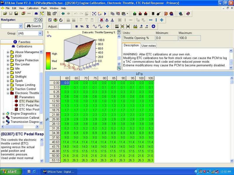
Here is the stock table from my tune. 30% pedal only gives you 5% TP.
If you are saying that you are seeing 30% TP as opposed to 30% APP, and it is dead, that is a different story.
Last edited by DrX; 11-27-2006 at 12:17 AM.
11-26-2006, 11:26 PM
#10
TECH Junkie
iTrader: (2)
Join Date: Mar 2005
Location: Spring, TX
Posts: 3,197
Likes: 0
Received 0 Likes
on
0 Posts
Do you think someone will make a fixed 90mm TB and a wiring harness to make all of this plug & play?
Are there any gains to switching to the 90mm TB and J-tube upgrade over the stock TB without these fixes?
Hopefully someone will have a easier fix to all of this.
I really don't like fooling with circuit boards or hacking up the factory wiring harnesses.
Jim
Are there any gains to switching to the 90mm TB and J-tube upgrade over the stock TB without these fixes?
Hopefully someone will have a easier fix to all of this.
I really don't like fooling with circuit boards or hacking up the factory wiring harnesses.
Jim

